


Filter by
Product Family

Gear Type

Shaft Diameter

Gear Pitch Diameter

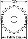
OD

Tooth Direction


Hub Diameter


RoHS
Export Control Classification Number (ECCN)
DFARS Specialty Metals
Performance
About Gears
Compare gear types, measure pitch and module, calculate mounting distance, increase speed or torque, and more.
High-Power Metal Helical Gear Racks
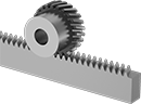 |  |
Parallel Gear on Gear Rack (Sold Separately) |
Pair these racks with parallel helical gears that have an opposite tooth direction to convert rotary motion to linear motion.
High-Power Metal Helical Gears
Crossed Gears
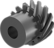 |
Crossed helical gears, also known as screw gears, can be configured to transmit motion at a 90° angle or in a straight line. To transmit motion at a 90° angle, pair two gears with the same tooth direction. To transmit motion in a straight line, make sure to get one left-hand and one right-hand gear.
For gears to mesh correctly, they must have the same pressure angle and pitch/module. To change speed and torque in your assembly, pair two gears with different numbers of teeth.
Hub | Keyway | Left-Hand Teeth | Right-Hand Teeth | |||||||||||||||||
|---|---|---|---|---|---|---|---|---|---|---|---|---|---|---|---|---|---|---|---|---|
Gear Pitch | Gear Module | No. of Teeth | Helix Angle | Gear Pitch Dia. | OD | Face Wd. | Dia. | Wd. | Bore Type | For Shaft Dia. | Wd. | Dp. | Material | Tooth Heat Treatment | Each | Each | ||||
20° Pressure Angle | ||||||||||||||||||||
| — | 1 | 13 | 45° | 18.4 mm | 20.38 mm | 10 mm | 15 mm | 10 mm | Round Bore | 6 mm | — | — | Black-Oxide 1045 Carbon Steel | Not Hardened | 3598N289 | 000000 | 3598N291 | 000000 | ||
| — | 1 | 26 | 45° | 36.8 mm | 38.77 mm | 10 mm | 30 mm | 10 mm | Round Bore | 10 mm | — | — | Black-Oxide 1045 Carbon Steel | Not Hardened | 3598N296 | 00000 | 3598N297 | 00000 | ||
| — | 1 | 30 | 45° | 42.4 mm | 44.43 mm | 10 mm | 35 mm | 10 mm | Round Bore | 10 mm | — | — | Black-Oxide 1045 Carbon Steel | Not Hardened | 3598N298 | 00000 | 3598N299 | 00000 | ||
| — | 1.5 | 10 | 45° | 21.2 mm | 24.21 mm | 15 mm | 16 mm | 10 mm | Round Bore | 8 mm | — | — | Black-Oxide 1045 Carbon Steel | Not Hardened | 3598N276 | 00000 | 3598N277 | 00000 | ||
| — | 1.5 | 13 | 45° | 27.6 mm | 30.58 mm | 15 mm | 23 mm | 10 mm | Round Bore | 10 mm | — | — | Black-Oxide 1045 Carbon Steel | Not Hardened | 3598N278 | 00000 | 3598N279 | 00000 | ||
| — | 1.5 | 26 | 45° | 55.2 mm | 58.15 mm | 15 mm | 40 mm | 10 mm | Round Bore | 12 mm | — | — | Black-Oxide 1045 Carbon Steel | Not Hardened | 3598N285 | 00000 | 3598N286 | 00000 | ||
14 1/2° Pressure Angle | ||||||||||||||||||||
| 16 | — | 16 | 45° | 1" | 1.09" | 1/2" | 0.86" | 0.5" | Keyed Bore with Set Screw | 1/2" | 0.125" | 0.062" | 1137 Carbon Steel | Hardened | 2585N11 | 00000 | 2585N12 | 00000 | ||
| 16 | — | 24 | 45° | 1 1/2" | 1.59" | 1/2" | 1.37" | 0.5" | Keyed Bore with Set Screw | 5/8" | 0.187" | 0.094" | 1137 Carbon Steel | Hardened | 2585N13 | 000000 | 2585N14 | 000000 | ||
| 16 | — | 32 | 45° | 2" | 2.09" | 1/2" | 1.87" | 0.5" | Keyed Bore with Set Screw | 5/8" | 0.187" | 0.094" | 1137 Carbon Steel | Hardened | 2585N15 | 000000 | 2585N16 | 000000 | ||
| 16 | — | 48 | 45° | 3" | 3.09" | 1/2" | 2.5" | 0.5" | Keyed Bore with Set Screw | 5/8" | 0.187" | 0.094" | 1137 Carbon Steel | Hardened | 2585N17 | 000000 | 2585N18 | 000000 | ||
| 12 | — | 18 | 45° | 1 1/2" | 1.62" | 3/4" | 1.34" | 0.5" | Keyed Bore with Set Screw | 5/8" | 0.187" | 0.094" | 1137 Carbon Steel | Hardened | 2585N22 | 000000 | 2585N23 | 000000 | ||
Parallel Gears
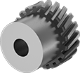 |
Pair two parallel gears to transmit motion in a straight line or a gear with a rack to convert rotary motion to linear motion. Make sure mating components have different tooth directions.
For gears to mesh correctly, they must have the same pressure angle and pitch/module. To change speed and torque in your assembly, pair two gears with different numbers of teeth.
Hub, mm | Left-Hand Teeth | Right-Hand Teeth | |||||||||||||||
|---|---|---|---|---|---|---|---|---|---|---|---|---|---|---|---|---|---|
Gear Module | No. of Teeth | Helix Angle | Gear Pitch Dia., mm | OD, mm | Face Wd., mm | Dia. | Wd. | Bore Type | For Shaft Dia., mm | Material | Tooth Heat Treatment | Each | Each | ||||
20° Pressure Angle | |||||||||||||||||
| 1 | 20 | 21 1/2° | 20 | 22 | 8 | 17 | 10 | Round Bore | 6 | 4140 Alloy Steel | Hardened | 3598N159 | 000000 | 3598N161 | 000000 | ||
| 1 | 30 | 21 1/2° | 30 | 32 | 8 | 25 | 10 | Round Bore | 10 | 4140 Alloy Steel | Hardened | 3598N171 | 000000 | 3598N172 | 000000 | ||
| 1 | 44 | 21 1/2° | 44 | 46 | 8 | 30 | 10 | Round Bore | 10 | 4140 Alloy Steel | Hardened | 3598N182 | 000000 | 3598N183 | 000000 | ||
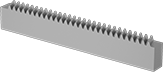
Parallel Gear Racks
| |
Parallel Gear on Gear Rack (Sold Separately) |
Pair these racks with parallel helical gears that have an opposite tooth direction to convert rotary motion to linear motion.
High-Load Metal Spiral Bevel Gears
 |
Gears Sold Separately |
 |
Large Gears |
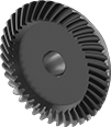
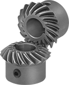
The spiral teeth on these bevel gears stay in contact longer than straight teeth, so they can handle heavier loads at higher speeds. Use them to transmit motion at a right angle while changing shaft speed and torque. Their teeth engage gradually, which reduces vibration and noise, and they’re hardened for extra wear resistance. All are carbon steel for good strength. They have a machinable bore, so you can customize the size within the For Shaft Diameter range listed.
A complete set consists of a large gear and a small gear, also known as a pinion (sold separately). For the gears to mesh correctly, they must have the same face width, pitch or module, and pressure angle.
Speed Ratio—The ratio by which shaft speed is reduced when transferring motion from the smaller to the larger gear. To increase shaft speed, transfer motion from the larger to the smaller gear. Changing shaft speed also changes torque: as speed decreases, torque increases. To achieve the speed ratio listed, match it across a set of compatible gears.
High-Power Metal Miter Gears
 |
Keyed Bore with Set Screw |
 |
 |
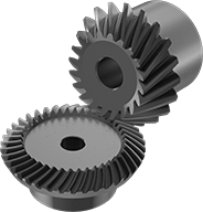
Also known as spiral miter gears, these gears have curved teeth that stay in contact longer than straight teeth so they handle heavier loads at higher speeds. They run quieter than standard miter gears because the teeth gradually engage. Use them to transmit motion at a right angle while maintaining shaft speed and torque. Gears are carbon steel for strength. Teeth are hardened for wear resistance.
Gears must be identical in order to mesh correctly; they're sold as a pair.
Hub | Keyway | |||||||||||||||||
|---|---|---|---|---|---|---|---|---|---|---|---|---|---|---|---|---|---|---|
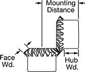
Gear Pitch | No. of Teeth | Pressure Angle | Gear Pitch Dia. | OD | Face Wd. | Overall Wd. | For Shaft Dia. | Mounting Distance | Material | Dia. | Wd. | Wd. | Dp. | Set Screw Thread Size | Pair | |||
Keyed Bore with Set Screw | ||||||||||||||||||
| 18 | 18 | 20° | 1" | 1.07" | 0.22" | 0.74" | 3/8" | 1.062" | 1117 Carbon Steel | 0.75" | 0.44" | 0.094" | 0.047" | 10-32 | 7655K1 | 0000000 | ||
| 12 | 15 | 20° | 1 1/4" | 1.36" | 0.3" | 0.86" | 1/2" | 1.25" | 1117 Carbon Steel | 1" | 0.5" | 0.125" | 0.063" | 1/4"-20 | 7655K2 | 000000 | ||
| 12 | 18 | 20° | 1 1/2" | 1.61" | 0.34" | 1.02" | 5/8" | 1.5" | 1117 Carbon Steel | 1.25" | 0.56" | 0.188" | 0.094" | 5/16"-18 | 7655K3 | 000000 | ||
| 10 | 20 | 20° | 2" | 2.13" | 0.47" | 1.36" | 3/4" | 2" | 1117 Carbon Steel | 1.625" | 0.78" | 0.188" | 0.094" | 5/16"-18 | 7655K4 | 000000 | ||
