


Filter by
Electrical Connection

Housing Material
Wire Connection
Environment
Shielding
Export Control Classification Number (ECCN)
DFARS Specialty Metals
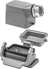
Compact Build-Your-Own Latching Connectors
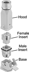 |
Build a connector that fits in tight spaces by combining male and female inserts and then pairing them with any base and hood of the same material. Use them to protect connections while maintaining access. The base and hood latch together securely, yet can be quickly detached for equipment repair or replacement. Once assembled, they’re rated NEMA 4X for protection against washdowns and NEMA 12 to resist oil/coolant dripping.
Hoods with Wire Inlet Connection
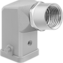 | 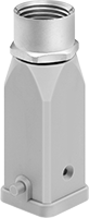 |
Side Conduit Connection—Female | Top Conduit Connection—Female |
Conduit | ||||||||||||||
|---|---|---|---|---|---|---|---|---|---|---|---|---|---|---|
For No. of Poles | Housing Material | Trade Size | Thread Type | Lg. | Wd. | Ht. | Temp. Range, ° F | Enclosure Rating | Certification | Flammability Rating | Each | |||
Side Conduit Connection—Female | ||||||||||||||
| 3, 4, 6 | Powder-Coated Zinc Alloy | 1/2 | NPT | 1.5" | 1.4" | 2.1" | -40 to 255 | IP67, NEMA 4X, NEMA 12 | UL Recognized Component | UL 94 V-0 | 7979K34 | 000000 | ||
| 3, 4, 6 | Stainless Steel | 1/2 | NPT | 1.8" | 1.3" | 2.1" | -40 to 255 | IP67, NEMA 4X, NEMA 12 | UL Recognized Component | UL 94 V-0 | 7979K52 | 000000 | ||
| 3, 4, 6 | Polycarbonate | 1/2 | NPT | 1.5" | 1.4" | 2.1" | -40 to 255 | IP44, NEMA 4X, NEMA 12 | UL Recognized Component | UL 94 V-0 | 7979K32 | 00000 | ||
Top Conduit Connection—Female | ||||||||||||||
| 3, 4, 6 | Powder-Coated Zinc Alloy | 1/2 | NPT | 1" | 1.4" | 2.4" | -40 to 255 | IP67, NEMA 4X, NEMA 12 | UL Recognized Component | UL 94 V-0 | 7979K33 | 00000 | ||
| 3, 4, 6 | Stainless Steel | 1/2 | NPT | 1.1" | 1.3" | 2.4" | -40 to 255 | IP67, NEMA 4X, NEMA 12 | UL Recognized Component | UL 94 V-0 | 7979K51 | 000000 | ||
| 3, 4, 6 | Polycarbonate | 1/2 | NPT | 1" | 1.4" | 2.4" | -40 to 255 | IP67, NEMA 4X, NEMA 12 | UL Recognized Component | UL 94 V-0 | 7979K31 | 00000 | ||
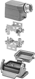
Multipurpose Build-Your-Own Latching Connectors
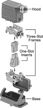 |
Hood and Base Sets
 |
Conduit | Temp., ° F | ||||||||||||||||||
|---|---|---|---|---|---|---|---|---|---|---|---|---|---|---|---|---|---|---|---|
For No. of Frame Slots | For Frame Lg. | No. of Latching Levers | Trade Size | Thread Type | Connection Gender | Lg. | Wd. | Ht. | Housing Material | Base Cover Style | Min. | Max. | Enclosure Rating | Certification | Electrical Connection | Each | |||
Wire Inlet Connection | |||||||||||||||||||
| 2 | 2" | 1 | 1/2 | NPT | Female | 3.1" | 1.7" | 2.8" | Powder-Coated Aluminum | Attached | -40 | 255 | IP65, NEMA 4X, NEMA 12 | UL Recognized Component | Latching Connector | 1829K51 | 000000 | ||
| 3 | 2.5" | 1 | 1/2 | NPT | Female | 3.7" | 1.7" | 3.4" | Powder-Coated Aluminum | Attached | -40 | 255 | IP65, NEMA 4X, NEMA 12 | UL Recognized Component | Latching Connector | 1829K52 | 00000 | ||
| 4 | 3.3" | 1 | 3/4 | NPT | Female | 4.5" | 1.7" | 3.6" | Powder-Coated Aluminum | Attached | -40 | 255 | IP65, NEMA 4X, NEMA 12 | UL Recognized Component | Latching Connector | 1829K53 | 00000 | ||
| 6 | 4.4" | 1 | 3/4 | NPT | Female | 5.5" | 1.7" | 4.1" | Powder-Coated Aluminum | Attached | -40 | 255 | IP65, NEMA 4X, NEMA 12 | UL Recognized Component | Latching Connector | 1829K54 | 00000 | ||
Hood and Base Sets with Two Frames
 |
Conduit | Temp., ° F | ||||||||||||||||||
|---|---|---|---|---|---|---|---|---|---|---|---|---|---|---|---|---|---|---|---|
No. of Frame Slots | Frame Material | No. of Latching Levers | Trade Size | Thread Type | Connection Gender | Lg. | Wd. | Ht. | Housing Material | Base Cover Style | Min. | Max. | Enclosure Rating | Certification | Electrical Connection | Each | |||
Wire Inlet Connection | |||||||||||||||||||
| 2 | Zinc Alloy | 1 | 1/2 | NPT | Female | 3.1" | 1.7" | 2.8" | Powder-Coated Aluminum | Attached | -40 | 255 | IP65, NEMA 4X, NEMA 12 | UL Recognized Component | Latching Connector | 1829K11 | 000000 | ||
| 3 | Zinc Alloy | 1 | 1/2 | NPT | Female | 3.7" | 1.7" | 3.4" | Powder-Coated Aluminum | Attached | -40 | 255 | IP65, NEMA 4X, NEMA 12 | UL Recognized Component | Latching Connector | 1829K12 | 00000 | ||
| 4 | Zinc Alloy | 1 | 3/4 | NPT | Female | 4.5" | 1.7" | 3.6" | Powder-Coated Aluminum | Attached | -40 | 255 | IP65, NEMA 4X, NEMA 12 | UL Recognized Component | Latching Connector | 1829K13 | 00000 | ||
| 6 | Zinc Alloy | 1 | 3/4 | NPT | Female | 5.5" | 1.7" | 4.1" | Powder-Coated Aluminum | Attached | -40 | 255 | IP65, NEMA 4X, NEMA 12 | UL Recognized Component | Latching Connector | 1829K14 | 00000 | ||
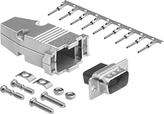
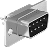
D-Sub Connectors
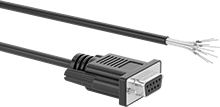
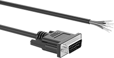
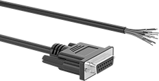
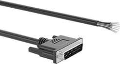
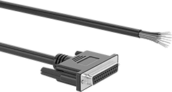
Straight Connectors—Solder Wire Inlet Connection
 |
DB9 | DB15 |
DB25 | DB37 |
DB50 | HD15 |
DB9 Connection | DB15 Connection | DB25 Connection | DB37 Connection | DB50 Connection | HD15 Connection | ||||||||||
|---|---|---|---|---|---|---|---|---|---|---|---|---|---|---|---|
For Wire Ga. | Housing Material | Each | Each | Each | Each | Each | Each | ||||||||
Unshielded Plugs | |||||||||||||||
| 28 to 20 | Plastic | ——— | 0 | ——— | 0 | ——— | 0 | ——— | 0 | 4600N133 | 000000 | ——— | 0 | ||
| 30 to 20 | Plastic | 2146T11 | 00000 | 2146T13 | 00000 | 2146T15 | 00000 | 2146T17 | 00000 | ——— | 0 | 2146T32 | 00000 | ||
Unshielded Sockets | |||||||||||||||
| 28 to 20 | Plastic | ——— | 0 | ——— | 0 | ——— | 0 | ——— | 0 | 4600N134 | 00000 | ——— | 0 | ||
| 30 to 20 | Plastic | 2146T12 | 0000 | 2146T14 | 0000 | 2146T16 | 0000 | 2146T18 | 0000 | ——— | 0 | 2146T33 | 0000 | ||
Shielded Plugs | |||||||||||||||
| 28 to 20 | Nickel-Plated Zinc Alloy | ——— | 0 | ——— | 0 | ——— | 0 | ——— | 0 | 4600N131 | 00000 | ——— | 0 | ||
| 30 to 20 | Nickel-Plated Zinc Alloy | 2146T52 | 0000 | 2146T54 | 00000 | 2146T58 | 00000 | 2146T61 | 00000 | ——— | 0 | 2146T56 | 00000 | ||
Shielded Sockets | |||||||||||||||
| 28 to 20 | Nickel-Plated Zinc Alloy | ——— | 0 | ——— | 0 | ——— | 0 | ——— | 0 | 4600N132 | 00000 | ——— | 0 | ||
| 30 to 20 | Nickel-Plated Zinc Alloy | 2146T51 | 0000 | 2146T53 | 00000 | 2146T57 | 00000 | 2146T59 | 00000 | ——— | 0 | 2146T55 | 00000 | ||
Straight Connectors—Crimp-On Wire Inlet Connection
|
DB9 | DB15 |
DB25 | DB37 |
DB50 |
DB9 Connection | DB15 Connection | DB25 Connection | DB37 Connection | DB50 Connection | |||||||||
|---|---|---|---|---|---|---|---|---|---|---|---|---|---|
For Wire Ga. | Housing Material | Each | Each | Each | Each | Each | |||||||
Unshielded Plugs | |||||||||||||
| 28 to 24 | Plastic | 94575T62 | 00000 | 94575T64 | 00000 | 94575T66 | 000000 | 94575T68 | 000000 | 4600N137 | 000000 | ||
Unshielded Sockets | |||||||||||||
| 28 to 24 | Plastic | 94575T61 | 0000 | 94575T63 | 0000 | 94575T65 | 00000 | 94575T67 | 00000 | 4600N138 | 00000 | ||
Shielded Plugs | |||||||||||||
| 28 to 24 | Nickel-Plated Zinc Alloy | 94575T14 | 00000 | 94575T15 | 00000 | 94575T16 | 00000 | 94575T28 | 00000 | 4600N135 | 00000 | ||
Shielded Sockets | |||||||||||||
| 28 to 24 | Nickel-Plated Zinc Alloy | 94575T17 | 00000 | 94575T18 | 00000 | 94575T19 | 00000 | 94575T29 | 00000 | 4600N136 | 00000 | ||
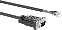
90° Elbow Connectors—Solder Wire Inlet Connection
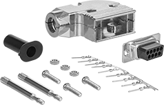
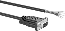
90° Elbow Connectors—Crimp-On Wire Inlet Connection
Washdown D-Sub Connectors
Straight Backshell Connectors
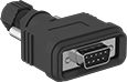 | 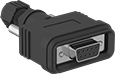 |
Plugs | Sockets |
DB9 | DB15 |
DB25 | HD15 |
DB9 Connection | DB15 Connection | DB25 Connection | HD15 Connection | |||||||||||||
|---|---|---|---|---|---|---|---|---|---|---|---|---|---|---|---|---|
For Wire Ga. | For Cable OD | Housing Material | Seal Material | Color | Features | Enclosure Rating | Each | Each | Each | Each | ||||||
Solder Wire Inlet Connection | ||||||||||||||||
Unshielded Plugs | ||||||||||||||||
| 30 to 20 | 0.14" to 0.27" | ABS | Nylon | Black | Adjustable Locknut, Rubber Gasket | IP67 | 6838N31 | 000000 | ——— | 0 | ——— | 0 | 6838N37 | 000000 | ||
| 30 to 20 | 0.24" to 0.39" | ABS | Nylon | Black | Adjustable Locknut, Rubber Gasket | IP67 | ——— | 0 | 6838N33 | 000000 | 6838N35 | 000000 | ——— | 0 | ||
Unshielded Sockets | ||||||||||||||||
| 30 to 20 | 0.14" to 0.27" | ABS | Nylon | Black | Adjustable Locknut, Rubber Gasket | IP67 | 6838N32 | 00000 | ——— | 0 | ——— | 0 | 6838N38 | 00000 | ||
| 30 to 20 | 0.24" to 0.39" | ABS | Nylon | Black | Adjustable Locknut, Rubber Gasket | IP67 | ——— | 0 | 6838N34 | 00000 | 6838N36 | 00000 | ——— | 0 | ||
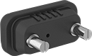
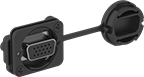
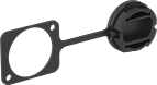
Straight Panel Mount Connectors
 |  |
Plugs | Sockets |
DB9 | DB15 |
DB25 | HD15 |
 |
Covers |
Plugs and Sockets | Covers | ||||||||||||||||||
|---|---|---|---|---|---|---|---|---|---|---|---|---|---|---|---|---|---|---|---|
For Panel Cutout | DB9 Connection | DB15 Connection | DB25 Connection | HD15 Connection | |||||||||||||||
For Wire Ga. | Ht. | Wd. | For Max. Panel Thk. | Housing Material | Seal Material | Color | Enclosure Rating | Each | Each | Each | Each | Each | |||||||
Solder Wire Inlet Connection | |||||||||||||||||||
Unshielded Plugs | |||||||||||||||||||
| 30 to 20 | 0.45" | 0.81" | 0.078" | Nickel-Plated Steel | Silicone Rubber | Black | IP67 | 6838N11 | 000000 | ——— | 0 | ——— | 0 | 6838N17 | 000000 | 6838N21 | 000000 | ||
| 30 to 20 | 0.45" | 1.13" | 0.078" | Nickel-Plated Steel | Silicone Rubber | Black | IP67 | ——— | 0 | 6838N13 | 000000 | ——— | 0 | ——— | 0 | 6838N22 | 00000 | ||
| 30 to 20 | 0.45" | 1.67" | 0.078" | Nickel-Plated Steel | Silicone Rubber | Black | IP67 | ——— | 0 | ——— | 0 | 6838N15 | 000000 | ——— | 0 | ——— | 0 | ||
Unshielded Sockets | |||||||||||||||||||
| 30 to 20 | 0.45" | 0.81" | 0.078" | Nickel-Plated Steel | Silicone Rubber | Black | IP67 | 6838N12 | 00000 | ——— | 0 | ——— | 0 | 6838N18 | 00000 | 6838N21 | 00000 | ||
| 30 to 20 | 0.45" | 1.13" | 0.078" | Nickel-Plated Steel | Silicone Rubber | Black | IP67 | ——— | 0 | 6838N14 | 00000 | ——— | 0 | ——— | 0 | 6838N22 | 00000 | ||
| 30 to 20 | 0.45" | 1.67" | 0.078" | Nickel-Plated Steel | Silicone Rubber | Black | IP67 | ——— | 0 | ——— | 0 | 6838N16 | 00000 | ——— | 0 | ——— | 0 | ||
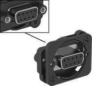
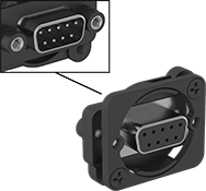
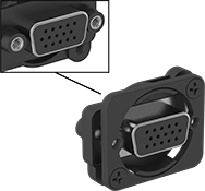
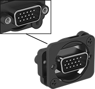
Panel-Mount D-Sub Connectors
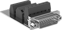 |  |
Plugs | Sockets |
DB9 | DB25 | DB15 | HD15 |
Create D-sub connection points in panels, cases, and enclosure walls. These connectors are often used in applications involving monitoring, control, and communication. They have screw terminals for connections, eliminating the need for solder or crimping tools.
For Panel Cutout | DB9 Connection | DB15 Connection | DB25 Connection | HD15 Connection | ||||||||||
|---|---|---|---|---|---|---|---|---|---|---|---|---|---|---|
For Wire Ga. | Ht. | Wd. | For Max. Panel Thk. | Mounting Fasteners Included | Each | Each | Each | Each | ||||||
Screw-Clamp-Terminal Wire Inlet Connection | ||||||||||||||
Shielded Plugs | ||||||||||||||
| 26 to 20 | 0.45" | 0.81" | 0.062" | Yes | 8048N11 | 000000 | ——— | 0 | ——— | 0 | 8048N17 | 000000 | ||
| 26 to 20 | 0.45" | 1.13" | 0.062" | Yes | ——— | 0 | 8048N13 | 000000 | ——— | 0 | ——— | 0 | ||
| 26 to 20 | 0.45" | 1.67" | 0.062" | Yes | ——— | 0 | ——— | 0 | 8048N15 | 000000 | ——— | 0 | ||
Shielded Sockets | ||||||||||||||
| 26 to 20 | 0.45" | 0.81" | 0.062" | Yes | 8048N12 | 00000 | ——— | 0 | ——— | 0 | ——— | 0 | ||
| 26 to 20 | 0.45" | 1.13" | 0.062" | Yes | ——— | 0 | 8048N14 | 00000 | ——— | 0 | ——— | 0 | ||
| 26 to 20 | 0.45" | 1.67" | 0.062" | Yes | ——— | 0 | ——— | 0 | 8048N16 | 00000 | 8048N18 | 00000 | ||
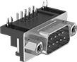
Circuit Board D-Sub Connectors
Straight
 |
DB9 | DB15 |
DB25 | DB37 |
DB9 Connection | DB15 Connection | DB25 Connection | DB37 Connection | ||||||||||
|---|---|---|---|---|---|---|---|---|---|---|---|---|---|
Housing Material | Color | Connection Method | Flammability Rating | Each | Each | Each | Each | ||||||
Solder and Terminal-Block Wire Inlet Connection | |||||||||||||
Unshielded Plugs | |||||||||||||
| Zinc-Plated Steel | Blue | Solder | UL 94 V-0 | 5063N22 | 00000 | 5063N23 | 00000 | 5063N24 | 00000 | ——— | 0 | ||
Unshielded Sockets | |||||||||||||
| Zinc-Plated Steel | Blue | Solder | UL 94 V-0 | 5063N26 | 0000 | 5063N27 | 0000 | 5063N28 | 0000 | 5063N29 | 000000 | ||
90° Elbow
 |
DB9 | DB15 |
DB25 | DB37 |
DB50 | HD15 |
DB9 Connection | DB15 Connection | DB25 Connection | DB37 Connection | DB50 Connection | HD15 Connection | ||||||||||||
|---|---|---|---|---|---|---|---|---|---|---|---|---|---|---|---|---|---|
Housing Material | Color | Connection Method | Flammability Rating | Each | Each | Each | Each | Each | Each | ||||||||
Solder and Terminal-Block Wire Inlet Connection | |||||||||||||||||
Unshielded Plugs | |||||||||||||||||
| Zinc-Plated Steel | Black | Solder | UL 94 V-0 | 5063N12 | 00000 | 5063N13 | 00000 | 5063N14 | 00000 | 5063N15 | 00000 | ——— | 0 | 5063N16 | 00000 | ||
| Nickel-Plated Steel | Black | Solder | UL 94 V-0 | ——— | 0 | ——— | 0 | ——— | 0 | ——— | 0 | 5063N11 | 000000 | ——— | 0 | ||
Unshielded Sockets | |||||||||||||||||
| Zinc-Plated Steel | Black | Solder | UL 94 V-0 | 5063N17 | 0000 | 5063N18 | 0000 | 5063N19 | 0000 | 5063N21 | 0000 | ——— | 0 | 5063N31 | 0000 | ||
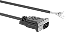
D-Sub Cords
Panel-Mount D-Sub Adapters


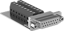
Sanitary Electric Multipurpose Han Connectors
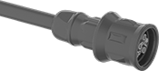
Plugs
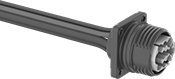 |  | |
12-Pole Plug with Ground Connection | Cap with Lanyard |
Plugs | Caps with Lanyard | |||||||||||||
|---|---|---|---|---|---|---|---|---|---|---|---|---|---|---|
Wire Lead | ||||||||||||||
No. of Poles | No. of Ground Connections | Voltage | Current | AWG | Lg. | Housing Material | Temp. Range, ° F | Food Industry Std. | Each | Each | ||||
Wire Lead Connection | ||||||||||||||
| 12 | 1 | 250V AC/250V DC 400V AC/400V DC | 10 amp 20 amp | 22 | 20" | Polypropylene | -40 to 250 | FDA Compliant 21 CFR 177.1500 FDA Compliant 21 CFR 177.1520 FDA Compliant 21 CFR 177.2600 | 6756N112 | 0000000 | 6756N113 | 000000 | ||
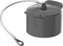
Sockets
 | 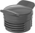 | |
12-Pole Socket with Ground Connection | Cap |
Sockets | Caps | |||||||||||||
|---|---|---|---|---|---|---|---|---|---|---|---|---|---|---|
Wire Lead | ||||||||||||||
No. of Poles | No. of Ground Connections | Voltage | Current | AWG | Lg., ft. | Housing Material | Temp. Range, ° F | Food Industry Std. | Each | Each | ||||
Wire Lead Connection | ||||||||||||||
| 12 | 1 | 250V AC/250V DC 400V AC/400V DC | 10 amp 20 amp | 22 | 33 | Polypropylene | -20 to 190 | FDA Compliant 21 CFR 177.1500 FDA Compliant 21 CFR 177.1520 FDA Compliant 21 CFR 177.2600 | 6756N111 | 000000000 | 6756N114 | 000000 | ||
Filtered D-Sub Connectors
Plugs |
Sockets |
DB9 |
DB15 |
DB25 |
DB37 |
With a ferrite filter block surrounding their contacts, these connectors control and reduce the electromagnetic (EMI) and radio frequency (RFI) interference traveling through them. They have solder cup terminals that hold wire leads in place when you’re soldering them, helping you create a stable connection.
Mounting Holes | DB9 Connection | DB15 Connection | DB25 Connection | DB37 Connection | |||||||||||
|---|---|---|---|---|---|---|---|---|---|---|---|---|---|---|---|
For Wire Ga. | Interference Reduction @ Freq. | Housing Material | No. of | Dia., mm | Flammability Rating | Each | Each | Each | Each | ||||||
Solder Wire Inlet Connection | |||||||||||||||
Shielded Plugs | |||||||||||||||
| 20 | 4 dB @ 1 GHz | Nickel-Plated Steel | 2 | 3 | UL 94 V-0 | 8609N11 | 00000 | 8609N12 | 00000 | 8609N13 | 00000 | 8609N14 | 000000 | ||
Shielded Sockets | |||||||||||||||
| 20 | 4 dB @ 1 GHz | Nickel-Plated Steel | 2 | 3 | UL 94 V-0 | 8609N15 | 0000 | 8609N16 | 0000 | 8609N17 | 0000 | ——— | 0 | ||
