


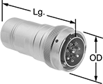
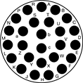
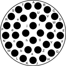
M23 Connectors
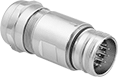 | 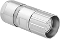 |  |  |
Plug | Socket | Male Receptacles | Male Receptacles with Mounting Holes |
Plugs, Sockets, and Receptacles | Caps | Replacement Housings | Replacement Inserts | |||||||||||||||
|---|---|---|---|---|---|---|---|---|---|---|---|---|---|---|---|---|---|---|
Low Current | High Current | |||||||||||||||||
No. of Poles | Pole Layout | Voltage | No. of Poles | Current, amp | No. of Poles | Current, amp | Wire Connection Method | Enclosure Rating | Each | Each | Each | Each | ||||||
Plugs | ||||||||||||||||||
| 12 | Clockwise | 200V AC/200V DC | 12 | 8 | — | — | Solder | IP67, IP69K, NEMA 4X | 1807T22 | 000000 | 1807T62 | 00000 | 1807T92 | 000000 | 1807T81 | 000000 | ||
| 12 | Counterclockwise | 200V AC/200V DC | 12 | 8 | — | — | Solder | IP67, IP69K, NEMA 4X | 1807T23 | 00000 | 1807T62 | 0000 | 1807T92 | 00000 | 1807T78 | 00000 | ||
| 16 | Clockwise | 160V AC/160V DC | 16 | 8 | — | — | Solder | IP67, IP69K, NEMA 4X | 1807T24 | 00000 | 1807T62 | 0000 | 1807T92 | 00000 | 1807T83 | 00000 | ||
| 17 | Clockwise | 160V AC/160V DC | 17 | 8 | — | — | Solder | IP67, IP69K, NEMA 4X | 1807T25 | 00000 | 1807T62 | 0000 | 1807T92 | 00000 | 1807T85 | 00000 | ||
| 19 | Clockwise | 100V AC/100V DC | 16 | 8 | 3 | 10 | Solder | IP67, IP69K, NEMA 4X | 1807T26 | 00000 | 1807T62 | 0000 | 1807T92 | 00000 | 1807T87 | 00000 | ||
Sockets | ||||||||||||||||||
| 12 | Clockwise | 200V AC/200V DC | 12 | 8 | — | — | Solder | IP67, IP69K, NEMA 4X | 1807T13 | 00000 | 1807T61 | 00000 | 1807T91 | 00000 | 1807T79 | 00000 | ||
| 12 | Counterclockwise | 200V AC/200V DC | 12 | 8 | — | — | Solder | IP67, IP69K, NEMA 4X | 1807T12 | 00000 | 1807T61 | 00000 | 1807T91 | 00000 | 1807T77 | 00000 | ||
| 16 | Counterclockwise | 160V AC/160V DC | 16 | 8 | — | — | Solder | IP67, IP69K, NEMA 4X | 1807T15 | 00000 | 1807T61 | 00000 | 1807T91 | 00000 | 1807T82 | 00000 | ||
| 17 | Counterclockwise | 160V AC/160V DC | 17 | 8 | — | — | Solder | IP67, IP69K, NEMA 4X | 1807T16 | 00000 | 1807T61 | 00000 | 1807T91 | 00000 | 1807T84 | 00000 | ||
| 19 | Counterclockwise | 100V AC/100V DC | 16 | 8 | 3 | 10 | Solder | IP67, IP69K, NEMA 4X | 1807T17 | 00000 | 1807T61 | 00000 | 1807T91 | 00000 | 1807T86 | 00000 | ||
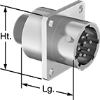
Male Receptacles | ||||||||||||||||||
| 12 | Clockwise | 200V AC/200V DC | 12 | 8 | — | — | Solder | IP67, IP69K, NEMA 4X | 1807T42 | 00000 | 1807T62 | 0000 | 1807T94 | 00000 | 1807T81 | 00000 | ||
| 12 | Counterclockwise | 200V AC/200V DC | 12 | 8 | — | — | Solder | IP67, IP69K, NEMA 4X | 1807T43 | 00000 | 1807T62 | 0000 | 1807T94 | 00000 | 1807T78 | 00000 | ||
| 16 | Clockwise | 160V AC/160V DC | 16 | 8 | — | — | Solder | IP67, IP69K, NEMA 4X | 1807T44 | 00000 | 1807T62 | 0000 | 1807T94 | 00000 | 1807T83 | 00000 | ||
| 19 | Clockwise | 100V AC/100V DC | 16 | 8 | 3 | 10 | Solder | IP67, IP69K, NEMA 4X | 1807T46 | 00000 | 1807T62 | 0000 | 1807T94 | 00000 | 1807T87 | 00000 | ||
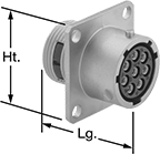
Male Receptacles with Mounting Holes | ||||||||||||||||||
| 12 | Clockwise | 200V AC/200V DC | 12 | 8 | — | — | Solder | IP67, IP69K, NEMA 4X | 1807T32 | 00000 | 1807T62 | 0000 | 1807T93 | 00000 | 1807T81 | 00000 | ||
| 12 | Counterclockwise | 200V AC/200V DC | 12 | 8 | — | — | Solder | IP67, IP69K, NEMA 4X | 1807T33 | 00000 | 1807T62 | 0000 | 1807T93 | 00000 | 1807T78 | 00000 | ||
| 16 | Clockwise | 160V AC/160V DC | 16 | 8 | — | — | Solder | IP67, IP69K, NEMA 4X | 1807T34 | 00000 | 1807T62 | 0000 | 1807T93 | 00000 | 1807T83 | 00000 | ||
| 17 | Clockwise | 160V AC/160V DC | 17 | 8 | — | — | Solder | IP67, IP69K, NEMA 4X | 1807T35 | 00000 | 1807T62 | 0000 | 1807T93 | 00000 | 1807T85 | 00000 | ||
| 19 | Clockwise | 100V AC/100V DC | 16 | 8 | 3 | 10 | Solder | IP67, IP69K, NEMA 4X | 1807T36 | 00000 | 1807T62 | 0000 | 1807T93 | 00000 | 1807T87 | 00000 | ||
Mil. Spec. Compatible Connectors
 |
 |  |  |  |  |
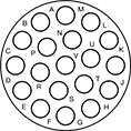
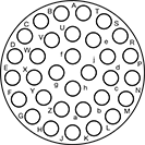
6 Poles (Clockwise) | 10 Poles (Clockwise) | 19 Poles (Clockwise) | 26 Poles (Clockwise) | 32 Poles (Clockwise) |
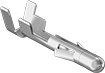
Mil. Spec. Plugs | Crimpers | ||||||||||||||
|---|---|---|---|---|---|---|---|---|---|---|---|---|---|---|---|
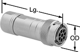
No. of Poles | Pole Layout | Voltage | Current, amp | For Wire Ga. | For Cable OD | OD | Lg. | Housing Material | Temp. Range, ° F | Connector Shell Size | Each | Each | |||
| 6 | Clockwise | 250V AC/250V DC | 7.5 | 30, 29, 28, 27, 26, 25, 24, 23, 22, 21, 20 | 0.12" to 0.2" | 0.9" | 2.7" | Nickel-Plated Zinc Alloy | -40 to 220 | 10 | 6168T11 | 000000 | 6168T3 | 000000000 | |
| 10 | Clockwise | 250V AC/250V DC | 7.5 | 30, 29, 28, 27, 26, 25, 24, 23, 22, 21, 20 | 0.24" to 0.39" | 1" | 2.9" | Nickel-Plated Zinc Alloy | -40 to 220 | 12 | 6168T12 | 00000 | 6168T3 | 00000000 | |
| 19 | Clockwise | 250V AC/250V DC | 7.5 | 30, 29, 28, 27, 26, 25, 24, 23, 22, 21, 20 | 0.24" to 0.39" | 1.2" | 2.9" | Nickel-Plated Zinc Alloy | -40 to 220 | 14 | 6168T13 | 00000 | 6168T3 | 00000000 | |
| 26 | Clockwise | 250V AC/250V DC | 7.5 | 30, 29, 28, 27, 26, 25, 24, 23, 22, 21, 20 | 0.35" to 0.57" | 1.3" | 3.1" | Nickel-Plated Zinc Alloy | -40 to 220 | 16 | 6168T14 | 00000 | 6168T3 | 00000000 | |
| 32 | Clockwise | 250V AC/250V DC | 7.5 | 30, 29, 28, 27, 26, 25, 24, 23, 22, 21, 20 | 0.35" to 0.57" | 1.4" | 3.1" | Nickel-Plated Zinc Alloy | -40 to 220 | 18 | 6168T15 | 00000 | 6168T3 | 00000000 | |
 |
 |  |  | 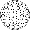 |
6 Poles (Counterclockwise) | 10 Poles (Counterclockwise) | 19 Poles (Counterclockwise) | 26 Poles (Counterclockwise) |
Mil. Spec. Sockets | Crimpers | ||||||||||||||
|---|---|---|---|---|---|---|---|---|---|---|---|---|---|---|---|
No. of Poles | Pole Layout | Voltage | Current, amp | For Wire Ga. | For Cable OD | OD | Lg. | Housing Material | Temp. Range, ° F | Connector Shell Size | Each | Each | |||
| 6 | Counterclockwise | 250V AC/250V DC | 7.5 | 30, 29, 28, 27, 26, 25, 24, 23, 22, 21, 20 | 0.12" to 0.2" | 0.9" | 2.7" | Nickel-Plated Zinc Alloy | -40 to 220 | 10 | 6168T31 | 000000 | 6168T3 | 000000000 | |
| 10 | Counterclockwise | 250V AC/250V DC | 7.5 | 30, 29, 28, 27, 26, 25, 24, 23, 22, 21, 20 | 0.24" to 0.39" | 1" | 2.9" | Nickel-Plated Zinc Alloy | -40 to 220 | 12 | 6168T32 | 00000 | 6168T3 | 00000000 | |
| 19 | Counterclockwise | 250V AC/250V DC | 7.5 | 30, 29, 28, 27, 26, 25, 24, 23, 22, 21, 20 | 0.24" to 0.39" | 1.2" | 2.9" | Nickel-Plated Zinc Alloy | -40 to 220 | 14 | 6168T43 | 00000 | 6168T3 | 00000000 | |
| 26 | Counterclockwise | 250V AC/250V DC | 7.5 | 30, 29, 28, 27, 26, 25, 24, 23, 22, 21, 20 | 0.35" to 0.57" | 1.3" | 3.1" | Nickel-Plated Zinc Alloy | -40 to 220 | 16 | 6168T34 | 00000 | 6168T3 | 00000000 | |
 |
| | | | |
6 Poles (Clockwise) | 10 Poles (Clockwise) | 19 Poles (Clockwise) | 26 Poles (Clockwise) | 32 Poles (Clockwise) |
Mil. Spec. Receptacles | Crimpers | |||||||||||||||
|---|---|---|---|---|---|---|---|---|---|---|---|---|---|---|---|---|
No. of Poles | Pole Layout | Voltage | Current, amp | For Wire Ga. | Lg. | Wd. | Ht. | Housing Material | For Panel Cutout Dia. | Temp. Range, ° F | Connector Shell Size | Each | Each | |||
| 6 | Clockwise | 250V AC/250V DC | 7.5 | 30, 29, 28, 27, 26, 25, 24, 23, 22, 21, 20 | 1.3" | 0.9" | 0.9" | Nickel-Plated Zinc Alloy | 0.72" | -40 to 220 | 10 | 6168T51 | 000000 | 6168T3 | 000000000 | |
| 10 | Clockwise | 250V AC/250V DC | 7.5 | 30, 29, 28, 27, 26, 25, 24, 23, 22, 21, 20 | 1.3" | 1" | 1" | Nickel-Plated Zinc Alloy | 0.81" | -40 to 220 | 12 | 6168T52 | 00000 | 6168T3 | 00000000 | |
| 19 | Clockwise | 250V AC/250V DC | 7.5 | 30, 29, 28, 27, 26, 25, 24, 23, 22, 21, 20 | 1.3" | 1.1" | 1.1" | Nickel-Plated Zinc Alloy | 0.91" | -40 to 220 | 14 | 6168T53 | 00000 | 6168T3 | 00000000 | |
| 26 | Clockwise | 250V AC/250V DC | 7.5 | 30, 29, 28, 27, 26, 25, 24, 23, 22, 21, 20 | 1.3" | 1.2" | 1.2" | Nickel-Plated Zinc Alloy | 1" | -40 to 220 | 16 | 6168T54 | 00000 | 6168T3 | 00000000 | |
| 32 | Clockwise | 250V AC/250V DC | 7.5 | 30, 29, 28, 27, 26, 25, 24, 23, 22, 21, 20 | 1.3" | 1.3" | 1.3" | Nickel-Plated Zinc Alloy | 1.1" | -40 to 220 | 18 | 6168T55 | 00000 | 6168T3 | 00000000 | |
 |
| | | |  |
6 Poles (Counterclockwise) | 10 Poles (Counterclockwise) | 19 Poles (Counterclockwise) | 26 Poles (Counterclockwise) | 32 Poles (Counterclockwise) |
Mil. Spec. Receptacles | Crimpers | |||||||||||||||
|---|---|---|---|---|---|---|---|---|---|---|---|---|---|---|---|---|
No. of Poles | Pole Layout | Voltage | Current, amp | For Wire Ga. | Lg. | Wd. | Ht. | Housing Material | For Panel Cutout Dia. | Temp. Range, ° F | Connector Shell Size | Each | Each | |||
| 6 | Counterclockwise | 250V AC/250V DC | 7.5 | 30, 29, 28, 27, 26, 25, 24, 23, 22, 21, 20 | 1.3" | 0.9" | 0.9" | Nickel-Plated Zinc Alloy | 0.72" | -40 to 220 | 10 | 6168T71 | 000000 | 6168T3 | 000000000 | |
| 10 | Counterclockwise | 250V AC/250V DC | 7.5 | 30, 29, 28, 27, 26, 25, 24, 23, 22, 21, 20 | 1.3" | 1" | 1" | Nickel-Plated Zinc Alloy | 0.81" | -40 to 220 | 12 | 6168T72 | 00000 | 6168T3 | 00000000 | |
| 19 | Counterclockwise | 250V AC/250V DC | 7.5 | 30, 29, 28, 27, 26, 25, 24, 23, 22, 21, 20 | 1.3" | 1.1" | 1.1" | Nickel-Plated Zinc Alloy | 0.91" | -40 to 220 | 14 | 6168T73 | 00000 | 6168T3 | 00000000 | |
| 26 | Counterclockwise | 250V AC/250V DC | 7.5 | 30, 29, 28, 27, 26, 25, 24, 23, 22, 21, 20 | 1.3" | 1.2" | 1.2" | Nickel-Plated Zinc Alloy | 1" | -40 to 220 | 16 | 6168T74 | 00000 | 6168T3 | 00000000 | |
| 32 | Counterclockwise | 250V AC/250V DC | 7.5 | 30, 29, 28, 27, 26, 25, 24, 23, 22, 21, 20 | 1.3" | 1.3" | 1.3" | Nickel-Plated Zinc Alloy | 1.1" | -40 to 220 | 18 | 6168T75 | 00000 | 6168T3 | 00000000 | |
Build-Your-Own Molex Circuit Board Connectors

Build-Your-Own Molex Compact Connectors
 |
Voltage, V AC | Current, amp | For Wire Ga. | Wire Connection Method | Pin Dia. | Pkg. Qty. | Pkg. | |||
|---|---|---|---|---|---|---|---|---|---|
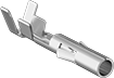
Molex Standard 0.062" Connection | |||||||||
| 250 | 5 | 30, 29, 28, 27, 26, 25, 24 | Crimp On | 0.062" | 100 | 69295K112 | 000000 | ||
 |
Voltage, V AC | Current, amp | For Wire Ga. | Wire Connection Method | For Pin Dia. | Pkg. Qty. | Pkg. | |||
|---|---|---|---|---|---|---|---|---|---|
Molex Standard 0.062" Connection | |||||||||
| 250 | 5 | 30, 29, 28, 27, 26, 25, 24 | Crimp On | 0.062" | 100 | 69295K116 | 00000 | ||
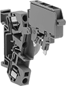
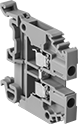
Quick-Connect Modular DIN-Rail Mount Terminal Blocks
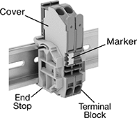 |
Terminal Blocks | Covers | End Stops | Adjacent Jumpers | Alternate Jumpers | |||||||||||||||||
|---|---|---|---|---|---|---|---|---|---|---|---|---|---|---|---|---|---|---|---|---|---|
Each | |||||||||||||||||||||
No. of Circuits | No. of Terminals per Circuit | For Wire Ga. | Wd., mm | Ht., mm | For DIN Rail Trade Size | Choose a Color | 1-24 | 25-Up | Each | Each | Insulation | Each | Insulation | Each | |||||||
300V AC/300V DC—15 amp per Circuit | |||||||||||||||||||||
| 2 | 2 | 28 to 12 | 5 | 64 | 3 | Blue, Gray | 9473T151 | 00000 | 00000 | 9473T154 | 00000 | 9473T144 | 00000 | Insulated | 9473T112 | 00000 | Insulated | 9473T113 | 00000 | ||
| 3 | 2 | 28 to 12 | 5 | 103 | 3 | Blue, Gray | 9473T162 | 00000 | 00000 | 9473T165 | 0000 | 9473T144 | 0000 | Insulated | 9473T112 | 0000 | Insulated | 9473T113 | 0000 | ||
600V AC/600V DC—20 amp per Circuit | |||||||||||||||||||||
| 1 | 2 | 28 to 12 | 5 | 53 | 3 | Black, Blue, Gray, Orange, Red, Yellow | 9473T1 | 0000 | 0000 | 9473T131 | 0000 | 9473T144 | 0000 | Insulated | 9473T112 | 0000 | Insulated | 9473T113 | 0000 | ||
| 1 | 2 | 28 to 12 | 6 | 59 | 3 | Black, Blue, Gray, Orange, Red, Yellow | 9473T24 | 0000 | 0000 | 9473T134 | 0000 | 9473T144 | 0000 | Insulated | 9473T115 | 0000 | Insulated | 9473T116 | 0000 | ||
| 1 | 3 | 28 to 12 | 5 | 64 | 3 | Black, Blue, Gray, Orange, Red, Yellow | 9473T8 | 0000 | 0000 | 9473T132 | 0000 | 9473T144 | 0000 | Insulated | 9473T112 | 0000 | Insulated | 9473T113 | 0000 | ||
| 1 | 3 | 28 to 12 | 6 | 73.5 | 3 | Black, Blue, Gray, Orange, Red, Yellow | 9473T32 | 0000 | 0000 | 9473T135 | 0000 | 9473T144 | 0000 | Insulated | 9473T115 | 0000 | Insulated | 9473T116 | 0000 | ||
| 1 | 4 | 28 to 12 | 5 | 75 | 3 | Black, Blue, Gray, Orange, Red, Yellow | 9473T16 | 0000 | 0000 | 9473T133 | 0000 | 9473T144 | 0000 | Insulated | 9473T112 | 0000 | Insulated | 9473T113 | 0000 | ||
| 1 | 4 | 28 to 12 | 6 | 86 | 3 | Black, Blue, Gray, Orange, Red, Yellow | 9473T39 | 0000 | 0000 | 9473T136 | 0000 | 9473T144 | 0000 | Insulated | 9473T115 | 0000 | Insulated | 9473T116 | 0000 | ||
| 2 | 2 | 28 to 12 | 6 | 73.5 | 3 | Blue, Gray | 9473T157 | 00000 | 0000 | 9473T161 | 0000 | 9473T144 | 0000 | Insulated | 9473T115 | 0000 | Insulated | 9473T116 | 0000 | ||
Blank | Numbered for Horizontal Rails | Numbered for Vertical Rails |
Each | |||||||||
|---|---|---|---|---|---|---|---|---|---|
For Terminal Block Wd., mm | Number Range | Includes | Markers per Card | Color | 1-24 | 25-Up | |||
Blank | |||||||||
| 5, 6, 8, 10, 12, 16, 25 | — | — | 100 | White | 9473T145 | 00000 | 00000 | ||
Numbered for Horizontal Rails | |||||||||
| 5, 6, 8, 10, 12, 16, 25 | 1 to 50 | Two of Each Number | 100 | White | 9473T146 | 00000 | 0000 | ||
Numbered for Vertical Rails | |||||||||
| 5, 6, 8, 10, 12, 16, 25 | 1 to 50 | Two of Each Number | 100 | White | 9473T147 | 00000 | 00000 | ||
Terminal Blocks | Covers | End Stops | Adjacent Jumpers | |||||||||||||||
|---|---|---|---|---|---|---|---|---|---|---|---|---|---|---|---|---|---|---|
Each | ||||||||||||||||||
No. of Circuits | No. of Terminals per Circuit | For Wire Ga. | Wd., mm | Ht., mm | Color | For DIN Rail Trade Size | 1-24 | 25-Up | Each | Each | Insulation | Each | ||||||
| 1 | 2 | 28 to 12 | 5 | 53 | Green/Yellow | 3 | 9473T82 | 000000 | 000000 | 9473T131 | 00000 | 9473T144 | 00000 | Insulated | 9473T114 | 00000 | ||
| 1 | 2 | 28 to 12 | 6 | 59 | Green/Yellow | 3 | 9473T86 | 00000 | 00000 | 9473T134 | 0000 | 9473T144 | 0000 | Insulated | 9473T117 | 0000 | ||
| 1 | 3 | 28 to 12 | 5 | 64 | Green/Yellow | 3 | 9473T83 | 00000 | 00000 | 9473T132 | 0000 | 9473T144 | 0000 | Insulated | 9473T114 | 0000 | ||
| 1 | 3 | 28 to 12 | 6 | 73.5 | Green/Yellow | 3 | 9473T87 | 00000 | 00000 | 9473T135 | 0000 | 9473T144 | 0000 | Insulated | 9473T117 | 0000 | ||
| 1 | 4 | 28 to 12 | 5 | 64 | Green/Yellow | 3 | 9473T155 | 00000 | 00000 | 9473T154 | 0000 | 9473T144 | 0000 | Insulated | 9473T114 | 0000 | ||
| 1 | 4 | 28 to 12 | 5 | 75 | Green/Yellow | 3 | 9473T84 | 00000 | 00000 | 9473T133 | 0000 | 9473T144 | 0000 | Insulated | 9473T114 | 0000 | ||
| 1 | 4 | 28 to 12 | 6 | 86 | Green/Yellow | 3 | 9473T88 | 00000 | 00000 | 9473T136 | 0000 | 9473T144 | 0000 | Insulated | 9473T117 | 0000 | ||
Blank | Numbered for Horizontal Rails | Numbered for Vertical Rails |
Each | |||||||||
|---|---|---|---|---|---|---|---|---|---|
For Terminal Block Wd., mm | Number Range | Includes | Markers per Card | Color | 1-24 | 25-Up | |||
Blank | |||||||||
| 5, 6, 8, 10, 12, 16, 25 | — | — | 100 | White | 9473T145 | 00000 | 00000 | ||
Numbered for Horizontal Rails | |||||||||
| 5, 6, 8, 10, 12, 16, 25 | 1 to 50 | Two of Each Number | 100 | White | 9473T146 | 00000 | 0000 | ||
Numbered for Vertical Rails | |||||||||
| 5, 6, 8, 10, 12, 16, 25 | 1 to 50 | Two of Each Number | 100 | White | 9473T147 | 00000 | 00000 | ||
 |
Terminal Blocks | Covers | End Stops | Adjacent Jumpers | ||||||||||||||||||||
|---|---|---|---|---|---|---|---|---|---|---|---|---|---|---|---|---|---|---|---|---|---|---|---|
For Fuse | Each | ||||||||||||||||||||||
No. of Circuits | No. of Terminals per Circuit | For Wire Ga. | Wd., mm | Ht., mm | Trade Size | Overall Dia. | Overall Lg., mm | Type | Circuit Status Indicator Type | Color | For DIN Rail Trade Size | 1-9 | 10-Up | Each | Each | Insulation | Each | ||||||
110V AC/110V DC—10 amp per Circuit | |||||||||||||||||||||||
| 1 | 2 | 28 to 12 | 8 | 60 | — | 5 mm | 20 | Ceramic, Glass | Blown Fuse | Gray | 3 | 9553T11 | 000000 | 000000 | 9553T2 | 00000 | 9473T144 | 00000 | Insulated | 9473T115 | 00000 | ||
| 1 | 2 | 28 to 12 | 10 | 60 | 3AG | 1/4" | — | Glass | Blown Fuse | Gray | 3 | 9553T13 | 00000 | 00000 | 9553T2 | 0000 | 9473T144 | 0000 | Insulated | 9473T115 | 0000 | ||
600V AC/600V DC—10 amp per Circuit | |||||||||||||||||||||||
| 1 | 2 | 28 to 12 | 8 | 60 | — | 5 mm | 20 | Ceramic, Glass | — | Gray | 3 | 9553T1 | 00000 | 00000 | 9553T2 | 0000 | 9473T144 | 0000 | Insulated | 9473T115 | 0000 | ||
| 1 | 2 | 28 to 12 | 10 | 60 | 3AG | 1/4" | — | Glass | — | Gray | 3 | 9553T3 | 00000 | 00000 | 9553T2 | 0000 | 9473T144 | 0000 | Insulated | 9473T115 | 0000 | ||
Blank | Numbered for Horizontal Rails | Numbered for Vertical Rails |
Each | |||||||||
|---|---|---|---|---|---|---|---|---|---|
For Terminal Block Wd., mm | Number Range | Includes | Markers per Card | Color | 1-24 | 25-Up | |||
Blank | |||||||||
| 5, 6, 8, 10, 12, 16, 25 | — | — | 100 | White | 9473T145 | 00000 | 00000 | ||
Numbered for Horizontal Rails | |||||||||
| 5, 6, 8, 10, 12, 16, 25 | 1 to 50 | Two of Each Number | 100 | White | 9473T146 | 00000 | 0000 | ||
Numbered for Vertical Rails | |||||||||
| 5, 6, 8, 10, 12, 16, 25 | 1 to 50 | Two of Each Number | 100 | White | 9473T147 | 00000 | 00000 | ||
Terminal Blocks | Covers | End Stops | Adjacent Jumpers | Alternate Jumpers | |||||||||||||||||
|---|---|---|---|---|---|---|---|---|---|---|---|---|---|---|---|---|---|---|---|---|---|
Each | |||||||||||||||||||||
No. of Circuits | No. of Terminals per Circuit | For Wire Ga. | Wd., mm | Ht., mm | Color | For DIN Rail Trade Size | 1-24 | 25-Up | Each | Each | Insulation | Each | Insulation | Each | |||||||
600V AC/600V DC—15 amp per Circuit | |||||||||||||||||||||
| 1 | 2 | 28 to 12 | 5 | 69.5 | Gray | 3 | 9473T168 | 000000 | 000000 | 9473T167 | 00000 | 9473T144 | 00000 | Insulated | 9473T112 | 00000 | Insulated | 9473T113 | 00000 | ||
Blank | Numbered for Horizontal Rails | Numbered for Vertical Rails |
Each | |||||||||
|---|---|---|---|---|---|---|---|---|---|
For Terminal Block Wd., mm | Number Range | Includes | Markers per Card | Color | 1-24 | 25-Up | |||
Blank | |||||||||
| 5, 6, 8, 10, 12, 16, 25 | — | — | 100 | White | 9473T145 | 00000 | 00000 | ||
Numbered for Horizontal Rails | |||||||||
| 5, 6, 8, 10, 12, 16, 25 | 1 to 50 | Two of Each Number | 100 | White | 9473T146 | 00000 | 0000 | ||
Numbered for Vertical Rails | |||||||||
| 5, 6, 8, 10, 12, 16, 25 | 1 to 50 | Two of Each Number | 100 | White | 9473T147 | 00000 | 00000 | ||
USB Connectors
 |
USB Std. | Transmission Speed, Mbit/s | For Wire Ga. | For Cable OD, mm | Housing Material | Color | Each | |||
|---|---|---|---|---|---|---|---|---|---|
Shielded | |||||||||
| 2.0 | 480 | 28 | 4.1 to 4.4 | Plastic | Black | 6282N13 | 000000 | ||
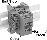
Space-Saving Modular DIN-Rail Mount Terminal Blocks
 |
 |
Terminal Blocks | Covers | End Stops | Bar Jumpers | ||||||||||||||||
|---|---|---|---|---|---|---|---|---|---|---|---|---|---|---|---|---|---|---|---|
Each | |||||||||||||||||||
No. of Circuits | No. of Terminals per Circuit | For Wire Ga. | Wd., mm | Ht., mm | For DIN Rail Trade Size | Enclosure Rating | Color | 1-24 | 25-Up | Each | Each | Insulation | Each | ||||||
250V AC—20 amp per Circuit | |||||||||||||||||||
| 1 | 2 | 28 to 12 | 5 | 27.5 | 2 | IP20 | Gray | 7641K61 | 00000 | 00000 | 7641K66 | 00000 | 7641K69 | 00000 | Noninsulated | 7641K56 | 000000 | ||
Blank | Numbered for Horizontal Rails | Numbered for Vertical Rails |
Each | |||||||||
|---|---|---|---|---|---|---|---|---|---|
For No. of Circuits | For Terminal Block Wd., mm | Number Range | Markers per Card | Color | 1-24 | 25-Up | |||
Blank | |||||||||
| 1 | 5 | — | 100 | White | 7641K811 | 00000 | 00000 | ||
Numbered for Horizontal Rails | |||||||||
| 1 | 5 | 1 to 100 | 100 | White | 7641K824 | 0000 | 0000 | ||
| 1 | 5 | 101 to 200 | 100 | White | 7641K825 | 0000 | 0000 | ||
Numbered for Vertical Rails | |||||||||
| 1 | 5 | 1 to 100 | 100 | White | 7641K822 | 0000 | 0000 | ||
| 1 | 5 | 101 to 200 | 100 | White | 7641K823 | 0000 | 0000 | ||
