

Filter by


Electrical Connection

Connection Method

Wire Connection
Wire Connection Method


Mounting Location
For Wire Gauge
Shielding


U.S.–Mexico–Canada Agreement (USMCA) Qualifying

Housing Finish
DFARS Specialty Metals
Export Control Classification Number (ECCN)
Circuit Board Mounting Orientation
Performance
Finish
Flammability Rating
System of Measurement
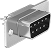
Circuit Board D-Sub Connectors
Straight
 |
 |  |
DB9 | DB15 |
 |  |
DB25 | DB37 |
DB9 Connection | DB15 Connection | DB25 Connection | DB37 Connection | ||||||||||
|---|---|---|---|---|---|---|---|---|---|---|---|---|---|
Housing Material | Color | Connection Method | Flammability Rating | Each | Each | Each | Each | ||||||
Solder and Terminal-Block Wire Inlet Connection | |||||||||||||
Unshielded Plugs | |||||||||||||
| Zinc-Plated Steel | Blue | Solder | UL 94 V-0 | 5063N22 | 00000 | 5063N23 | 00000 | 5063N24 | 00000 | ——— | 0 | ||
Unshielded Sockets | |||||||||||||
| Zinc-Plated Steel | Blue | Solder | UL 94 V-0 | 5063N26 | 0000 | 5063N27 | 0000 | 5063N28 | 0000 | 5063N29 | 000000 | ||
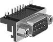
90° Elbow
 |
| |
DB9 | DB15 |
| |
DB25 | DB37 |
 |  |
DB50 | HD15 |
DB9 Connection | DB15 Connection | DB25 Connection | DB37 Connection | DB50 Connection | HD15 Connection | ||||||||||||
|---|---|---|---|---|---|---|---|---|---|---|---|---|---|---|---|---|---|
Housing Material | Color | Connection Method | Flammability Rating | Each | Each | Each | Each | Each | Each | ||||||||
Solder and Terminal-Block Wire Inlet Connection | |||||||||||||||||
Unshielded Plugs | |||||||||||||||||
| Zinc-Plated Steel | Black | Solder | UL 94 V-0 | 5063N12 | 00000 | 5063N13 | 00000 | 5063N14 | 00000 | 5063N15 | 00000 | ——— | 0 | 5063N16 | 00000 | ||
| Nickel-Plated Steel | Black | Solder | UL 94 V-0 | ——— | 0 | ——— | 0 | ——— | 0 | ——— | 0 | 5063N11 | 000000 | ——— | 0 | ||
Unshielded Sockets | |||||||||||||||||
| Zinc-Plated Steel | Black | Solder | UL 94 V-0 | 5063N17 | 0000 | 5063N18 | 0000 | 5063N19 | 0000 | 5063N21 | 0000 | ——— | 0 | 5063N31 | 0000 | ||
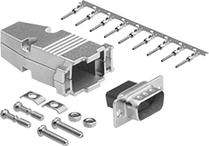
D-Sub Connectors
PLCs
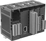 |
Our most scalable PLCs give your system room to grow. With support for up to 512 inputs and outputs, these PLCs can automate multiple processes at the same time, including those with scanners and other high-speed devices. They have serial connectivity, so you can integrate HMIs, legacy equipment, and other compatible devices. These PLCs support a variety of communication protocols, so they can control devices from many different manufacturers.
Once you download the manufacturer’s free software, start programming using an IEC standard language, such as Ladder Logic. When you’re ready, transfer your program to the PLC with a USB Mini-B cord or USB-C cord. Use the software to monitor, test, and troubleshoot issues in real time. These PLCs mount to 35 mm DIN rail in your electrical cabinet.
These PLCs have digital inputs and outputs.
Digital Signal Input/Output Expansion Modules
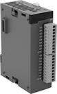 |
Add expansion modules to these PLCs when your system grows or needs new functionality. All modules have an LED status indicator to show the device is powered and running.
Increase the number of digital inputs and outputs you can control with these PLCs. These modules communicate using on-off or high-low signals, so you can integrate devices such as limit switches and lights.
Transistor Output—PLCs with transistor outputs are ideal for devices that switch multiple times per second, such as indicator lights and stepper motor drives.
NPN Output Signal—NPN outputs, also called sinking outputs, work only with PNP devices. If you need to connect different devices, use an output converter or signal converter (both not included).
Line Driver—Modules with line driver inputs accept differential signals from high-resolution encoders often used in robotics, CNC, and motion control systems.
NPN Open Collector—Modules with PNP/NPN open collector inputs accept single voltage signals from standard encoders and sensors.
