



























Filter by
Product Family
System of Measurement
Maximum Flow
Flow Measurement Unit
Calibrated With
Minimum Flow
Wetted Parts Material
Fitting Material


Maximum Temperature
Flow Measurement Type
Body Material
Connects To

Body Shape

Fitting Connection
Maximum Pressure @ Temperature
Measures
Graduations
Export Control Classification Number (ECCN)

DFARS Specialty Metals
Flowmeters
Cylindrical Body
 | 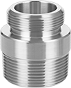 | 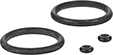 |
Female | Replacement Straights | Replacement Flowmeter Repair Kits |
Polypropylene Fitting—Polypropylene fittings work with a wide range of chemicals. However, they can crack from impact or when overtightened.
PVC Fitting—PVC fittings work with a wide range of chemicals. However, they can crack from impact or when overtightened.
Brass Fitting—Brass fittings resist impact better than polypropylene and PVC fittings.
316 Stainless Steel Fitting—316 stainless steel fittings resist impact better than polypropylene and PVC fittings.
Calibration Certificate Traceable to NIST—Flowmeters with a calibration certificate traceable to NIST states that the flowmeter has passed a test for accuracy.
Flowmeters | Replacement Straights | Replacement Flowmeter Repair Kits | ||||||||||||||||
|---|---|---|---|---|---|---|---|---|---|---|---|---|---|---|---|---|---|---|
Flow | Temp., ° F | Flowmeters | Calibration Certificate Traceable to NIST | |||||||||||||||
US Customary, gpm | Metric, L/min | Overall Ht. | Accuracy | Max. Pressure @ Temp. | Min. | Max. | Seal Material | Mounting Position | Each | Each | Each | Each | ||||||
Acrylic Plastic Body with Polypropylene Fittings | ||||||||||||||||||
3/8 NPT Female | ||||||||||||||||||
| 0.025 to 0.25 | 0.1 to 1 | 8 3/16" | ±5% | 150 psi @ 70° F | 33 | 150 | Fluoroelastomer | Vertical | 4350K512 | 0000000 | ——— | 0 | ——— | 0 | ——— | 0 | ||
| 0.05 to 0.5 | 0.2 to 2 | 8 3/16" | ±5% | 150 psi @ 70° F | 33 | 150 | Fluoroelastomer | Vertical | 4350K513 | 000000 | ——— | 0 | ——— | 0 | ——— | 0 | ||
| 0.1 to 1 | 0.4 to 4 | 8 3/16" | ±5% | 150 psi @ 70° F | 33 | 150 | Fluoroelastomer | Vertical | 4350K41 | 000000 | ——— | 0 | ——— | 0 | ——— | 0 | ||
| 0.2 to 2 | 1 to 7.5 | 8 3/16" | ±5% | 150 psi @ 70° F | 33 | 150 | Fluoroelastomer | Vertical | 4350K46 | 000000 | ——— | 0 | ——— | 0 | ——— | 0 | ||
| 0.3 to 3 | 1.5 to 11 | 8 3/16" | ±5% | 150 psi @ 70° F | 33 | 150 | Fluoroelastomer | Vertical | 4350K47 | 000000 | ——— | 0 | ——— | 0 | ——— | 0 | ||
Acrylic Plastic Body with PVC Fittings | ||||||||||||||||||
3/8 NPT Female | ||||||||||||||||||
| 0.1 to 1 | — | 8 1/4" | ±3% | 125 psi @ 70° F | 33 | 130 | EPM Rubber | Vertical | 8051K951 | 000000 | ——— | 0 | 8051K272 | 000000 | 6766T301 | 000000 | ||
| 0.2 to 2 | — | 8 1/4" | ±3% | 125 psi @ 70° F | 33 | 130 | EPM Rubber | Vertical | 8051K954 | 000000 | ——— | 0 | 8051K272 | 00000 | 6766T301 | 00000 | ||
| 0.3 to 3.5 | — | 8 1/4" | ±3% | 125 psi @ 70° F | 33 | 130 | EPM Rubber | Vertical | 8051K957 | 000000 | ——— | 0 | 8051K272 | 00000 | 6766T301 | 00000 | ||
| 0.5 to 5 | — | 8 1/4" | ±3% | 125 psi @ 70° F | 33 | 130 | EPM Rubber | Vertical | 8051K961 | 000000 | ——— | 0 | 8051K272 | 00000 | 6766T301 | 00000 | ||
Acrylic Plastic Body with Brass Fittings | ||||||||||||||||||
3/8 NPT Female | ||||||||||||||||||
| 0.1 to 1 | — | 8 1/4" | ±3% | 125 psi @ 70° F | 33 | 130 | EPM Rubber | Vertical | 8051K948 | 000000 | 8051K962 | 0000000 | 8051K249 | 00000 | 6766T301 | 00000 | ||
| 0.2 to 2 | — | 8 1/4" | ±3% | 125 psi @ 70° F | 33 | 130 | EPM Rubber | Vertical | 8051K952 | 000000 | 8051K965 | 000000 | 8051K249 | 00000 | 6766T301 | 00000 | ||
| 0.3 to 3.5 | — | 8 1/4" | ±3% | 125 psi @ 70° F | 33 | 130 | EPM Rubber | Vertical | 8051K955 | 000000 | 8051K968 | 000000 | 8051K249 | 00000 | 6766T301 | 00000 | ||
| 0.5 to 5 | — | 8 1/4" | ±3% | 125 psi @ 70° F | 33 | 130 | EPM Rubber | Vertical | 8051K958 | 000000 | 8051K972 | 000000 | 8051K249 | 00000 | 6766T301 | 00000 | ||
Acrylic Plastic Body with 316 Stainless Steel Fittings | ||||||||||||||||||
3/8 NPT Female | ||||||||||||||||||
| 0.1 to 1 | — | 8 1/4" | ±3% | 125 psi @ 70° F | 33 | 130 | EPM Rubber | Vertical | 8051K949 | 000000 | ——— | 0 | 8051K257 | 000000 | 6766T301 | 00000 | ||
| 0.2 to 2 | — | 8 1/4" | ±3% | 125 psi @ 70° F | 33 | 130 | EPM Rubber | Vertical | 8051K953 | 000000 | ——— | 0 | 8051K257 | 000000 | 6766T301 | 00000 | ||
| 0.3 to 3.5 | — | 8 1/4" | ±3% | 125 psi @ 70° F | 33 | 130 | EPM Rubber | Vertical | 8051K956 | 000000 | ——— | 0 | 8051K257 | 000000 | 6766T301 | 00000 | ||
| 0.5 to 5 | — | 8 1/4" | ±3% | 125 psi @ 70° F | 33 | 130 | EPM Rubber | Vertical | 8051K959 | 000000 | ——— | 0 | 8051K257 | 000000 | 6766T301 | 00000 | ||
Flow Transmitters
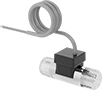 |
Turbine Flow Measurement |
Flow Measurement Type | Pipe Connections | Flow Range, gpm | End-to-End Lg. | Accuracy | Max. Pressure @ Temp. | Temp. Range, ° F | Input Voltage Range, V DC | Mounting Position | Field Recalibratable | Pulse Freq., Hz | Each | |||
|---|---|---|---|---|---|---|---|---|---|---|---|---|---|---|
One 4-20 mA Analog Transmitter/Digital Pulse Output—Wire Lead Connection | ||||||||||||||
Nylon Body with Nylon Fitting | ||||||||||||||
| Turbine | 3/8 NPT Male | 0.13 to 1.3 | 2 5/32" | ±3% | 362 psi @ 212° F | -4 to 212 | 5 to 24 | Any Angle | No | 56 to 565 | 4386N202 | 0000000 | ||
| Turbine | 3/8 NPT Male | 0.26 to 4 | 2 5/32" | ±3% | 362 psi @ 212° F | -4 to 212 | 5 to 24 | Any Angle | No | 36 to 553 | 4386N203 | 000000 | ||
| Turbine | 3/8 NPT Male | 0.53 to 9.2 | 2 5/32" | ±3% | 362 psi @ 212° F | -4 to 212 | 5 to 24 | Any Angle | No | 25 to 435 | 4386N204 | 000000 | ||
Brass Body with Brass Fitting | ||||||||||||||
| Turbine | 3/8 NPT Male | 0.5 to 2.11 | 2 5/32" | ±3% | 362 psi @ 212° F | -4 to 212 | 5 to 24 | Any Angle | No | 132 to 559 | 4386N206 | 000000 | ||
| Turbine | 3/8 NPT Male | 0.8 to 6.6 | 2 5/32" | ±3% | 362 psi @ 212° F | -4 to 212 | 5 to 24 | Any Angle | No | 46 to 383 | 4386N207 | 000000 | ||
High-Temperature Flowmeters with Digital Display
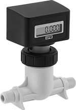 |
Check the flow rate of liquids up to 200° F from an easy-to-read digital display instead of a scale or dial. These flowmeters measure flow by counting how many times their turbine turns as liquid flows through. To avoid clogging the turbine and other damage to these flowmeters, use them only with clean, low-viscosity liquids. Mount them inline with your pipe system. Their fittings are polypropylene, which works with a wide range of chemicals. NEMA and IP rated, these flowmeters stand up to dust, weather, corrosion, and water from washdowns.
These flowmeters are calibrated with water but can be used with other liquids. If you’re using these with a liquid other than water, you’ll need to calculate the flow rate by multiplying the number shown on the scale by the specific-gravity conversion factor for your liquid.
Temp., ° F | ||||||||||||||
|---|---|---|---|---|---|---|---|---|---|---|---|---|---|---|
Flow, gpm | End-to-End Lg. | Overall Ht. | Accuracy | Max. Pressure @ Temp. | Min. | Max. | Seal Material | Mounting Position | Batteries Included | Enclosure Rating | Each | |||
Polypropylene Body with Polypropylene Fittings | ||||||||||||||
3/8 NPT Male | ||||||||||||||
| 0.4 to 4 | 4 3/4" | 5 3/8" | ±2% | 300 psi @ 70° F | 33 | 200 | Fluoroelastomer | Any Angle | Yes | IP56 NEMA 4X | 3562K17 | 0000000 | ||
| 0.8 to 8 | 4 3/4" | 5 3/8" | ±2% | 300 psi @ 70° F | 33 | 200 | Fluoroelastomer | Any Angle | Yes | IP56 NEMA 4X | 3562K11 | 000000 | ||
High-Temperature Flowmeters
 |
Male |
Measure the flow rate of high-temperature liquids. Built with a polysulfone body and fluoroelastomer seals, these flowmeters handle temperatures up to 212°F without degrading. As liquid flows through, it pushes an indicator up the scale to show the flow rate. Mount them vertically inline with your piping system so liquid flows up from the bottom. Union fittings make it easy to position the scale so it's visible. The fittings are plastic, so they work with a wide range of chemicals. Male NPT connections thread directly into female ports on your piping, eliminating the need for adapters.
These flowmeters are calibrated using water but can be used with other liquids by applying a specific-gravity conversion factor.
Flow | Temp., ° F | ||||||||||||
|---|---|---|---|---|---|---|---|---|---|---|---|---|---|
US Customary, gpm | Metric, L/min | Overall Ht. | Accuracy | Max. Pressure @ Temp. | Min. | Max. | Seal Material | Mounting Position | Features | Each | |||
Polysulfone Body with Polypropylene Fittings | |||||||||||||
3/8 NPT Male | |||||||||||||
| 0.1 to 1 | 0.4 to 4 | 6 3/16" | ±4% | 175 psi @ 70° F | -10 | 212 | Fluoroelastomer | Vertical | Union Fittings | 4400K67 | 0000000 | ||
| 0.2 to 2 | 0.75 to 7.5 | 6 3/16" | ±4% | 175 psi @ 70° F | -10 | 212 | Fluoroelastomer | Vertical | Union Fittings | 4400K68 | 000000 | ||
Polysulfone Body with Polysulfone Fittings | |||||||||||||
3/8 NPT Male | |||||||||||||
| 0.5 to 5 | 1.8 to 18 | 6 3/16" | ±4% | 175 psi @ 70° F | -10 | 212 | Fluoroelastomer | Vertical | Union Fittings | 4400K74 | 000000 | ||
High-Temperature Panel-Mount Flowmeters
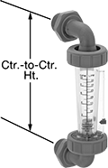 | 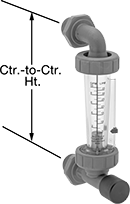 |
Male Flowmeters | Male, Flowmeters with Flow-Control Knob |
Install these flowmeters in an instrument panel to measure the flow rate of hot water and other liquids reaching up to 212° F. They should be mounted vertically, so liquid flows up from the bottom. As liquid flows through, it pushes an indicator up the scale, showing you the flow rate.
These flowmeters are calibrated with water but can be used with other liquids. If you’re using these with a liquid other than water, you’ll need to calculate the flow rate by multiplying the number shown on the scale by the specific-gravity conversion factor for your liquid.
Flow-Control Knob—Flowmeters with a flow-control knob let you open and close the inlet valve to adjust the flow rate within the range.
Flow | Temp., ° F | Flowmeters | Flowmeters with Flow-Control Knob | ||||||||||||
|---|---|---|---|---|---|---|---|---|---|---|---|---|---|---|---|
US Customary, gpm | Metric, L/min | Overall Ht. | Ctr.-to-Ctr. Ht. | Accuracy | Max. Pressure @ Temp. | Min. | Max. | Seal Material | Mounting Position | Each | Each | ||||
Polysulfone Body with Polysulfone Fittings | |||||||||||||||
3/8 NPT Male | |||||||||||||||
| 0.025 to 0.25 | 0.1 to 1 | 7" | 6" | ±4% | 175 psi @ 70° F | 33 | 212 | Fluoroelastomer | Vertical | 4215K66 | 0000000 | 4215K76 | 0000000 | ||
| 0.1 to 1 | 0.4 to 4 | 7" | 6" | ±4% | 175 psi @ 70° F | 33 | 212 | Fluoroelastomer | Vertical | 4215K67 | 000000 | 4215K77 | 000000 | ||
| 0.2 to 2 | 0.75 to 7.5 | 7" | 6" | ±4% | 175 psi @ 70° F | 33 | 212 | Fluoroelastomer | Vertical | 4215K68 | 000000 | 4215K78 | 000000 | ||
| 0.5 to 5 | 1.8 to 18 | 7" | 6" | ±4% | 175 psi @ 70° F | 33 | 212 | Fluoroelastomer | Vertical | 4215K69 | 000000 | 4215K79 | 000000 | ||
Fixed-Set-Point Flow Switches
 |
Style B |
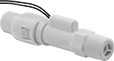
Since they come factory set to a specific set point, these switches are easier to install than adjustable flow switches. As flowing liquid pushes an internal piston, the switch reads the position of the piston to measure the flow. When the piston passes the set point, the switch actuates. They’re accurate in any mounting position.
These switches are calibrated with and measure water accurately. They can also be used with other liquids by applying your liquid’s specific-gravity conversion factor to calculate the new set point.
Choose a fitting material that is compatible with the liquid you intend to run through your line.
Straight
|
Style B |
Polypropylene Fitting—Polypropylene and PPS fittings work with a wide range of chemicals. However, they can crack from impact or when overtightened.
SPST—SPST (single pole, single throw) switches turn one device from off to on (normally open).
Style | Pipe Size | Thread Type | Gender | Set Point, gpm | Approx. Difference Between Set Point and Reset Point, gpm | Max. Pressure @ Temp. | Temp. Range, ° F | Max. Switching Current @ Voltage | End-to-End Lg. | Mounting Position | Each | |||
|---|---|---|---|---|---|---|---|---|---|---|---|---|---|---|
Polypropylene Body with Polypropylene Fittings | ||||||||||||||
SPST | ||||||||||||||
| B | 3/8 | NPT | Male | 0.25 | 0.05 | 125 psi @ 70° F | 33 to 212 | 400 mA @ 30V AC 170 mA @ 120V AC 80 mA @ 240V AC 300 mA @ 30V DC 130 mA @ 120V DC 60 mA @ 240V DC | 4" | Any Angle | 42015K21 | 000000 | ||
| B | 3/8 | NPT | Male | 0.5 | 0.1 | 125 psi @ 70° F | 33 to 212 | 400 mA @ 30V AC 170 mA @ 120V AC 80 mA @ 240V AC 300 mA @ 30V DC 130 mA @ 120V DC 60 mA @ 240V DC | 4" | Any Angle | 42015K22 | 00000 | ||
| B | 3/8 | NPT | Male | 1 | 0.2 | 125 psi @ 70° F | 33 to 212 | 400 mA @ 30V AC 170 mA @ 120V AC 80 mA @ 240V AC 300 mA @ 30V DC 130 mA @ 120V DC 60 mA @ 240V DC | 4" | Any Angle | 42015K23 | 00000 | ||
| B | 3/8 | NPT | Male | 1.5 | 0.3 | 125 psi @ 70° F | 33 to 212 | 400 mA @ 30V AC 170 mA @ 120V AC 80 mA @ 240V AC 300 mA @ 30V DC 130 mA @ 120V DC 60 mA @ 240V DC | 4" | Any Angle | 42015K24 | 00000 | ||
| B | 3/8 | NPT | Male | 2 | 0.4 | 125 psi @ 70° F | 33 to 212 | 400 mA @ 30V AC 170 mA @ 120V AC 80 mA @ 240V AC 300 mA @ 30V DC 130 mA @ 120V DC 60 mA @ 240V DC | 4" | Any Angle | 42015K25 | 00000 | ||
Flow Sights with Indicator for Water and Oil
 |  |
Rotor Indicator Front Window | Rotor Indicator Front and Back Window |
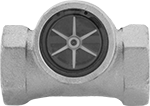
The indicator moves when flow is present, so it’s easy to visually confirm flow from a distance.
Rotor Indicator—Rotor indicator is the most obvious indicator of flow for maximum visibility.
Bronze Body—Sights with a bronze body are harder and more durable than sights with a brass body for a longer service life.
316 Stainless Steel Body—Sights with a 316 stainless steel body are more corrosion resistant than sights with a brass or bronze body.
Front and Back Window—Back window can be backlit to increase the visibility of dark liquids.
Window | Indicator | |||||||||||||||
|---|---|---|---|---|---|---|---|---|---|---|---|---|---|---|---|---|
Pipe Size | Thread Type | Gender | Temp. Range, ° F | Dia. | Type | End-to-End Lg. | Ht. | Max. Pressure @ Temp. | Direction of Flow | Material | Color | For Use With | Each | |||
Rotor Indicator | ||||||||||||||||
Bronze Body | ||||||||||||||||
| 3/8 | NPT | Female | -20 to 200 | 1 3/4" | Front | 3 1/8" | 2 1/8" | 125 psi @ 70° F | Left to Right, Right to Left | Acetal | White | Water, Oil | 4195K14 | 0000000 | ||
| 3/8 | NPT | Female | -20 to 200 | 1 3/4" | Front and Back | 3 1/8" | 2 1/8" | 125 psi @ 70° F | Left to Right, Right to Left | Acetal | White | Water, Oil | 4200K42 | 000000 | ||
316 Stainless Steel Body | ||||||||||||||||
| 3/8 | NPT | Female | 40 to 200 | 1 5/8" | Front and Back | 3" | 2 1/8" | 125 psi @ 70° F | Left to Right, Right to Left | 316 Stainless Steel | — | Water, Oil | 5088K54 | 000000 | ||
Panel-Mount Flow Sights for Water, Oil, and Inert Gas
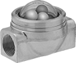 |
The included mounting ring lets you install these sights in instrument panels. They have three ball indicators that bounce in the domed-top window to show flow in your line.
Flow Sights | Repair Kits | ||||||||||||||||||
|---|---|---|---|---|---|---|---|---|---|---|---|---|---|---|---|---|---|---|---|
Window | Indicator | ||||||||||||||||||
Pipe Size | Thread Type | Gender | Temp. Range, ° F | Dia. | Type | End-to-End Lg. | Ht. | Max. Pressure @ Temp. | Panel Cutout Dia. | Direction of Flow | No. of | Material | For Use With | Each | Each | ||||
Ball Indicator | |||||||||||||||||||
Brass Body | |||||||||||||||||||
| 3/8 | NPT | Female | 35 to 120 | 1 5/8" | Domed Top | 3 1/8" | 2 1/8" | 150 psi @ 70° F | 2 3/8" | Bottom to Top, Left to Right, Right to Left, Top to Bottom | 3 | White Polyethylene White Polyethylene Green Acrylic Plastic | Water, Oil, Inert Gas | 4202K14 | 0000000 | 4202K216 | 000000 | ||
High-Temperature Flowmeter/Totalizers
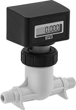 |
With one meter, these flowmeter/totalizers measure the flow rate and total flow volume of high-temperature liquid up to 200° F. They count how many times their turbine turns as liquid passes through to measure flow. To avoid clogging the turbine and other damage to the sensor, use them only with clean, low-viscosity liquids. The batch total can be reset after each metering application. They come set for batch totalization, but you can disable the reset function to operate as a cumulative totalizer. They measure flow correctly no matter the mounting orientation.
These flowmeter/totalizers are calibrated with water. You can use them with other liquids, but they may not measure accurately if the liquid’s viscosity differs from water.
Flowmeter/Totalizers | |||||||||||||||
|---|---|---|---|---|---|---|---|---|---|---|---|---|---|---|---|
Max. Volume Displayed | Temp., ° F | ||||||||||||||
Connections | Flow, gpm | End-to-End Lg. | Accuracy | Total | Batch | Max. Pressure @ Temp. | Mounting Position | Batteries Included | Enclosure Rating | Min. | Max. | Each | |||
Turbine Flow Measurement | |||||||||||||||
Polypropylene Body with Polypropylene Fitting and Fluoroelastomer Seal | |||||||||||||||
| 3/8 NPT Male | 0.8 to 8 | 4 3/4" | ±2% | 99,999.9 Gallons | 999,999 Gallons | 300 psi @ 70° F | Any Angle | Yes | IP56 NEMA 4X | 33 | 200 | 3562K31 | 0000000 | ||
High-Temperature Flow Sights for Water and Oil
 |
Flapper Indicator |
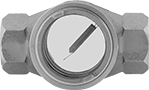
Withstand twice the temperature of standard flow sights for applications with temperatures up to 400° F. These sights let you visually confirm flow and inspect liquid color and clarity. The flapper indicator moves when flow is present, so it’s easy to confirm flow from a distance. Backlight the back window to increase the visibility of dark liquids. The brass body of these sights resists corrosion.
Window | |||||||||||||||
|---|---|---|---|---|---|---|---|---|---|---|---|---|---|---|---|
Pipe Size | Thread Type | Gender | Temp. Range, ° F | Dia. | Type | End-to-End Lg. | Ht. | Max. Pressure @ Temp. | Direction of Flow | Indicator Material | For Use With | Each | |||
Flapper Indicator | |||||||||||||||
Brass Body | |||||||||||||||
| 3/8 | NPT | Female | 0 to 400 | 1 7/8" | Front and Back | 3 1/4" | 2 1/4" | 150 psi @ 70° F | Any Direction | 304 Stainless Steel | Water, Oil | 4213K141 | 0000000 | ||
Compact Flow Sights for Water and Oil
 |
The low-profile body fits in areas with limited clearance. These sights let you visually confirm flow and inspect liquid color and clarity. The back window can be backlit to increase the visibility of dark liquids.
303 Stainless Steel Body—Sights with a 303 stainless steel body are more corrosion resistant than sights with a brass or zinc-plated steel body.
Window | ||||||||||||||
|---|---|---|---|---|---|---|---|---|---|---|---|---|---|---|
Pipe Size | Thread Type | Gender | Temp. Range, ° F | Lg. | Type | Hex Size | End-to-End Lg. | Max. Pressure @ Temp. | Direction of Flow | For Use With | Each | |||
No Indicator | ||||||||||||||
Brass Body | ||||||||||||||
| 3/8 | NPTF | Female | -40 to 180 | 1 1/8" | Front and Back | 1" | 4 1/4" | 425 psi @ 150° F | Bottom to Top, Left to Right, Right to Left, Top to Bottom | Water, Oil | 1138K53 | 0000000 | ||
Zinc-Plated Steel Body | ||||||||||||||
| 3/8 | NPT | Female | 0 to 180 | 1 3/8" | Front and Back | 15/16" | 2 7/8" | 125 psi @ 70° F | Bottom to Top, Left to Right, Right to Left, Top to Bottom | Water, Oil | 5069K55 | 00000 | ||
303 Stainless Steel Body | ||||||||||||||
| 3/8 | NPT | Female | 0 to 180 | 1 3/8" | Front and Back | 15/16" | 2 7/8" | 125 psi @ 70° F | Bottom to Top, Left to Right, Right to Left, Top to Bottom | Water, Oil | 6955T23 | 00000 | ||
Compact Flow Sights with Indicator for Water and Oil
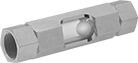 |
For visual confirmation of flow from a distance, these sights have a ball indicator that moves when flow is present. They have a low-profile body for installation in pipelines with limited clearance. Backlight the back window to increase the visibility of dark liquids.
303 Stainless Steel Body—Sights with a 303 stainless steel body are more corrosion resistant than sights with a brass or zinc-plated steel body.
Window | Indicator | |||||||||||||||
|---|---|---|---|---|---|---|---|---|---|---|---|---|---|---|---|---|
Pipe Size | Thread Type | Gender | Temp. Range, ° F | Lg. | Type | Hex Size | End-to-End Lg. | Max. Pressure @ Temp. | Direction of Flow | Material | Color | For Use With | Each | |||
Ball Indicator | ||||||||||||||||
Brass Body | ||||||||||||||||
| 3/8 | NPTF | Female | -40 to 180 | 1 1/8" | Front and Back | 1" | 4 1/4" | 425 psi @ 150° F | Bottom to Top, Left to Right, Right to Left, Top to Bottom | Nylon | White | Water, Oil | 1138K63 | 0000000 | ||
Zinc-Plated Steel Body | ||||||||||||||||
| 3/8 | NPT | Female | 0 to 180 | 1 3/8" | Front and Back | 15/16" | 4 1/8" | 125 psi @ 70° F | Bottom to Top, Left to Right, Right to Left, Top to Bottom | Nylon | White | Water, Oil | 5069K63 | 00000 | ||
303 Stainless Steel Body | ||||||||||||||||
| 3/8 | NPT | Female | 0 to 180 | 1 3/8" | Front and Back | 15/16" | 4 1/8" | 125 psi @ 70° F | Bottom to Top, Left to Right, Right to Left, Top to Bottom | Nylon | White | Water, Oil | 6955T28 | 000000 | ||
High-Temperature Totalizers with Digital Display
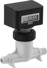 |
The digital display on these totalizers makes it easy to check the total amount of high-temperature liquid—up to 200° F—passing through your system. They measure flow volume by counting how many times their turbine turns as liquid passes through. To avoid clogging the turbine and other damage to these totalizers, use them only with clean, low-viscosity liquids. The batch total can be reset after each metering application. They come set for batch totalization, but you can disable the reset function to operate as a cumulative totalizer. They measure flow accurately no matter the mounting orientation. Rated NEMA 4X and IP65, they seal out dust and protect against washdowns and corrosion.
These totalizers are calibrated with water. You can use them with other liquids, but they may not measure accurately if the liquid’s viscosity differs from water.
Max. Volume Displayed | Temp., ° F | ||||||||||||||||
|---|---|---|---|---|---|---|---|---|---|---|---|---|---|---|---|---|---|
Connections | Flow, gpm | Total | Batch | End-to-End Lg. | Accuracy | Max. Pressure @ Temp. | Min. | Max. | Seal Material | Mounting Position | Display Type | Batteries Included | Enclosure Rating | Each | |||
Polypropylene Body with Polypropylene Fittings | |||||||||||||||||
| 3/8 NPT Male | 0.8 to 8 | 99,999.9 Gallons | 999,999 Gallons | 4 3/4" | ±2% | 300 psi @ 70° F | 33 | 200 | Fluoroelastomer | Any Angle | Digital | Yes | IP56 NEMA 4X | 3562K21 | 0000000 | ||
Fixed-Set-Point High-Pressure Flow Switches
Straight
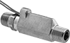 |
SPST—SPST (single pole, single throw) switches turn one device from off to on (normally open).
Pipe Connections | Set Point, gpm | Approx. Difference Between Set Point and Reset Point, gpm | Max. Pressure @ Temp. | Temp. Range, ° F | Max. Switching Current @ Voltage | End-to-End Lg. | Each | |||
|---|---|---|---|---|---|---|---|---|---|---|
SPST | ||||||||||
Brass Body with Brass Fittings | ||||||||||
| 3/8 NPT Male | 0.25 | 0.05 | 1,500 psi @ 70° F | -20 to 275 | 0.4 amp @ 30V AC 0.17 amp @ 120V AC 0.08 amp @ 240V AC 0.3 amp @ 30V DC 0.13 amp @ 120V DC 0.06 amp @ 240V DC | 3 7/16" | 4960K51 | 0000000 | ||
| 3/8 NPT Male | 0.5 | 0.1 | 1,500 psi @ 70° F | -20 to 275 | 0.4 amp @ 30V AC 0.17 amp @ 120V AC 0.08 amp @ 240V AC 0.3 amp @ 30V DC 0.13 amp @ 120V DC 0.06 amp @ 240V DC | 3 7/16" | 4960K52 | 000000 | ||
| 3/8 NPT Male | 1 | 0.2 | 1,500 psi @ 70° F | -20 to 275 | 0.4 amp @ 30V AC 0.17 amp @ 120V AC 0.08 amp @ 240V AC 0.3 amp @ 30V DC 0.13 amp @ 120V DC 0.06 amp @ 240V DC | 3 7/16" | 4960K53 | 000000 | ||
| 3/8 NPT Male | 1.5 | 0.3 | 1,500 psi @ 70° F | -20 to 275 | 0.4 amp @ 30V AC 0.17 amp @ 120V AC 0.08 amp @ 240V AC 0.3 amp @ 30V DC 0.13 amp @ 120V DC 0.06 amp @ 240V DC | 3 7/16" | 4960K54 | 000000 | ||
| 3/8 NPT Male | 2 | 0.4 | 1,500 psi @ 70° F | -20 to 275 | 0.4 amp @ 30V AC 0.17 amp @ 120V AC 0.08 amp @ 240V AC 0.3 amp @ 30V DC 0.13 amp @ 120V DC 0.06 amp @ 240V DC | 3 7/16" | 4960K55 | 000000 | ||
316 Stainless Steel Body with 316 Stainless Steel Fittings | ||||||||||
| 3/8 NPT Male | 0.25 | 0.05 | 1,500 psi @ 70° F | -20 to 275 | 0.4 amp @ 30V AC 0.17 amp @ 120V AC 0.08 amp @ 240V AC 0.3 amp @ 30V DC 0.13 amp @ 120V DC 0.06 amp @ 240V DC | 3 7/16" | 4960K71 | 000000 | ||
| 3/8 NPT Male | 0.5 | 0.1 | 1,500 psi @ 70° F | -20 to 275 | 0.4 amp @ 30V AC 0.17 amp @ 120V AC 0.08 amp @ 240V AC 0.3 amp @ 30V DC 0.13 amp @ 120V DC 0.06 amp @ 240V DC | 3 7/16" | 4960K72 | 000000 | ||
| 3/8 NPT Male | 2 | 0.4 | 1,500 psi @ 70° F | -20 to 275 | 0.4 amp @ 30V AC 0.17 amp @ 120V AC 0.08 amp @ 240V AC 0.3 amp @ 30V DC 0.13 amp @ 120V DC 0.06 amp @ 240V DC | 3 7/16" | 4960K75 | 000000 | ||
Flow Sights for Water and Oil
 |
Visually confirm flow and inspect the color and clarity of your process media. These sights have a back window that can be backlit to increase the visibility of dark liquids.
316 Stainless Steel Body—Sights with a 316 stainless steel body are more corrosion resistant than sights with a bronze body.
Window | ||||||||||||||
|---|---|---|---|---|---|---|---|---|---|---|---|---|---|---|
Pipe Size | Thread Type | Gender | Temp. Range, ° F | Dia. | Type | End-to-End Lg. | Ht. | Max. Pressure @ Temp. | Direction of Flow | For Use With | Each | |||
No Indicator | ||||||||||||||
Bronze Body | ||||||||||||||
| 3/8 | NPT | Female | -20 to 200 | 1 3/4" | Front and Back | 3 1/8" | 2 1/8" | 125 psi @ 70° F | Any Direction | Water, Oil | 4206K22 | 0000000 | ||
316 Stainless Steel Body | ||||||||||||||
| 3/8 | NPT | Female | 40 to 200 | 1 5/8" | Front and Back | 3" | 2 1/8" | 125 psi @ 70° F | Any Direction | Water, Oil | 4206K72 | 000000 | ||
Quick-Clean Flow Sights for Water
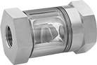 |
To maintain a clear view of your process media without disrupting flow, twist the tubular window to clear debris and buildup with the internal wipers. These sights have a rotor indicator that spins when liquid moves through your line so you can visually confirm flow from a distance.
Window | Indicator | |||||||||||||||
|---|---|---|---|---|---|---|---|---|---|---|---|---|---|---|---|---|
Pipe Size | Thread Type | Gender | Temp. Range, ° F | Dia. | Type | Hex Size | End-to-End Lg. | Max. Pressure @ Temp. | Direction of Flow | Material | Color | For Use With | Each | |||
Rotor Indicator | ||||||||||||||||
Brass Body | ||||||||||||||||
| 3/8 | NPT | Female | 40 to 212 | 1 3/8" | Tubular | 1 1/2" | 2 3/4" | 230 psi @ 70° F | Left to Right, Right to Left | Acetal | Red | Water | 6416T2 | 0000000 | ||
High-Pressure Flow Sights for Water and Oil
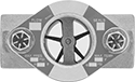 |
Rotor Indicator |
Rated for more than double the pressure of standard flow sights, these can withstand pressures up to 400 psi. They’re used to visually confirm flow and inspect the color and clarity of your process media. All have an indicator that moves when flow is present for checking flow from a distance. Backlight the back window to increase the visibility of dark liquids.
Rotor Indicator—Rotor indicator provides a more obvious indication of flow than a flapper indicator for maximum visibility.
Window | Indicator | |||||||||||||||
|---|---|---|---|---|---|---|---|---|---|---|---|---|---|---|---|---|
Pipe Size | Thread Type | Gender | Temp. Range, ° F | Dia. | Type | End-to-End Lg. | Ht. | Max. Pressure @ Temp. | Direction of Flow | Material | Color | For Use With | Each | |||
Rotor Indicator | ||||||||||||||||
Bronze Body | ||||||||||||||||
| 3/8 | NPT | Female | 0 to 350 | 1 1/8" | Front and Back | 3 1/4" | 2 1/2" | 400 psi @ 70° F | Right to Left | PPS | Brown | Water, Oil | 4195K32 | 0000000 | ||
