


Filter by
System of Measurement
Thread Type
Fitting Connection

DFARS Specialty Metals
REACH
U.S.–Mexico–Canada Agreement (USMCA) Qualifying
RoHS
Export Control Classification Number (ECCN)
Hardness
For Use With
Size-Checking Gauge Class
Thread Direction
Connects To
Mounting Position
Body Material
Hole Diameter
Pipe Schedule

Finish
Mounting Location
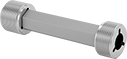
Threaded Plug Gauges with Handle for Pipe Threads
 |
NPSM Thread |
Pipe Size | Pitch Dia. Tolerance | Hardness | Material | Features | Each | |||
|---|---|---|---|---|---|---|---|---|
NPSM Thread | ||||||||
| 1/8 | -0.0003" to 0.0003" | Rockwell C60 | Tool Steel | Taperlock Handle | 6744N11 | 0000000 | ||
| 1/4 | -0.0003" to 0.0003" | Rockwell C60 | Tool Steel | Taperlock Handle | 6744N12 | 000000 | ||
| 3/8 | -0.0003" to 0.0003" | Rockwell C60 | Tool Steel | Taperlock Handle | 6744N13 | 000000 | ||
| 1/2 | -0.0003" to 0.0003" | Rockwell C60 | Tool Steel | Taperlock Handle | 6744N14 | 000000 | ||
| 3/4 | -0.0003" to 0.0003" | Rockwell C60 | Tool Steel | Taperlock Handle | 6744N15 | 000000 | ||
Threaded Ring Gauges for Pipe Threads
Class X Gauge—NPSM Thread
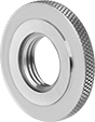 |
Use gauges with NPSM threads in pairs for go/no-go tests. Go gauges check the maximum external thread size, and no-go gauges check the minimum. If the threads you’re testing thread into the go gauge but not the no-go gauge, they’re within tolerance.
Go Gauge | No-Go Gauge | ||||||||
|---|---|---|---|---|---|---|---|---|---|
Pipe Size | Hardness | Material | Pitch Dia. Tolerance | Each | Pitch Dia. Tolerance | Each | |||
| 1/8 | Rockwell C60 | Tool Steel | 0" to 0.0003" | 2365A152 | 0000000 | -0.0003" to 0" | 2365A157 | 0000000 | |
| 1/4 | Rockwell C60 | Tool Steel | 0" to 0.0003" | 2365A153 | 000000 | -0.0003" to 0" | 2365A158 | 000000 | |
| 3/8 | Rockwell C60 | Tool Steel | 0" to 0.0003" | 2365A154 | 000000 | -0.0003" to 0" | 2365A159 | 000000 | |
| 1/2 | Rockwell C60 | Tool Steel | 0" to 0.0003" | 2365A155 | 000000 | -0.0003" to 0" | 2365A161 | 000000 | |
| 3/4 | Rockwell C60 | Tool Steel | 0" to 0.0003" | 2365A156 | 000000 | -0.0003" to 0" | 2365A162 | 000000 | |
Socket-Connect Flowmeter/Totalizers with Remote Display
Sensors
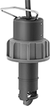 |
Sensors thread onto the tee fitting.
Tee Fittings
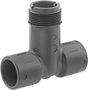 |
Tee fittings mount inline with your pipe. They have two unthreaded socket ends that bond to unthreaded PVC pipe with PVC cement and primer.
Temp., ° F | |||||||||||
|---|---|---|---|---|---|---|---|---|---|---|---|
Inlet/Outlet Connection | Sensor Connection | Pipe Schedule | Flow, gpm | Max. Pressure @ Temp. | Min. | Max. | Mounting Position | Each | |||
PVC Body | |||||||||||
| 1/2 Socket Connect Female Inlet Pipe × 1/2 Socket Connect Female Outlet Pipe | 1 1/4 NPSM Threaded Male Pipe | 80 | 1 to 18.9 | 180 psi @ 70° F | 33 | 149 | Any Angle | 4114K231 | 0000000 | ||
| 3/4 Socket Connect Female Inlet Pipe × 3/4 Socket Connect Female Outlet Pipe | 1 1/4 NPSM Threaded Male Pipe | 80 | 1.7 to 33.2 | 180 psi @ 70° F | 33 | 149 | Any Angle | 4114K232 | 000000 | ||
| 1 Socket Connect Female Inlet Pipe × 1 Socket Connect Female Outlet Pipe | 1 1/4 NPSM Threaded Male Pipe | 80 | 2.7 to 53.9 | 180 psi @ 70° F | 33 | 149 | Any Angle | 4114K233 | 000000 | ||
| 1 1/2 Socket Connect Female Inlet Pipe × 1 1/2 Socket Connect Female Outlet Pipe | 1 1/4 NPSM Threaded Male Pipe | 80 | 6.4 to 126.9 | 180 psi @ 70° F | 33 | 149 | Any Angle | 4114K235 | 000000 | ||
| 2 Socket Connect Female Inlet Pipe × 2 Socket Connect Female Outlet Pipe | 1 1/4 NPSM Threaded Male Pipe | 80 | 10.5 to 209.2 | 180 psi @ 70° F | 33 | 149 | Any Angle | 4114K236 | 000000 | ||
| 3 Socket Connect Female Inlet Pipe × 3 Socket Connect Female Outlet Pipe | 1 1/4 NPSM Threaded Male Pipe | 80 | 23 to 460.8 | 180 psi @ 70° F | 33 | 149 | Any Angle | 4114K238 | 000000 | ||
Humidity-Indicating Plugs
 |
 |
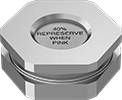
40% Spot Indicator |
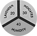 | 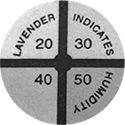 |
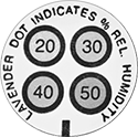
20%, 30%, 40% Pie Indicator | 20%, 30%, 40%, 50% Pie Indicator |
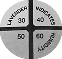 |  |
30%, 40%, 50%. 60% Pie Indicator | 20%, 30%, 40%, 50% Spot Indicator |
Monitor humidity in sealed containers without opening them, protecting the inside from contamination. These plugs are often used on plastic bags, storage containers, and electrical housings. Consisting of a mounting nut and two gaskets for a tight seal, these plugs install through a hole in a flexible barrier. Remove one gasket and reverse the nut to install plugs in a rigid container. Watch the indicator disc through the nut’s viewing window—it will change color as humidity rises and falls. Made of anodized aluminum, these plugs resist corrosion and are lightweight. They meet military and SAE standards for humidity indicators.
Humidity Points | Accuracy | Ht. | Wd. | For Hole Dia. | Thread Type | Pipe Size | Indicator Use | Mil. Spec. | Specs. Met | Each | |||
|---|---|---|---|---|---|---|---|---|---|---|---|---|---|
Anodized Aluminum | |||||||||||||
Pie Indicator | |||||||||||||
| 20%, 30%, 40%, 50% | ±5% | 5/8" | 1 3/8" | 1.05" | NPSM | 3/4 | Reversible | MIL-I-8835 | SAE AS26860 Type 2 | 2229K13 | 000000 | ||
| 20%, 30%, 40% | ±5% | 5/8" | 1 3/8" | 1.05" | NPSM | 3/4 | Reversible | MIL-I-8835 | SAE AS26860 Type 2 | 2229K14 | 00000 | ||
| 30%, 40%, 50%, 60% | ±5% | 5/8" | 1 3/8" | 1.05" | NPSM | 3/4 | Reversible | MIL-I-8835 | SAE AS26860 Type 2 | 2229K16 | 00000 | ||
Spot Indicator | |||||||||||||
| 20%, 30%, 40%, 50% | ±5% | 5/8" | 1 3/8" | 1.05" | NPSM | 3/4 | Reversible | MIL-I-8835 | SAE AS26860 Type 2 | 2229K12 | 00000 | ||
| 40% | ±5% | 5/8" | 1 3/8" | 1.05" | NPSM | 3/4 | Reversible | MIL-I-8835 | SAE AS26860 Type 2 | 2229K11 | 00000 | ||
