


Filter by
For Use With

Power Source
Maximum Flow Rate
Maximum Pressure
Housing Material
Flow Rate
Pump Type
DFARS Specialty Metals
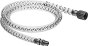
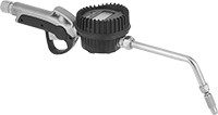
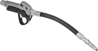
Container-Mount Oil Dispensers
 |  |
A (Pail Not Included) | Style B |
For Container | Base | For Max. Viscosity | |||||||||||||||||
|---|---|---|---|---|---|---|---|---|---|---|---|---|---|---|---|---|---|---|---|
Style | Size, gal. | Max. Dia. | Max. Ht. | oz. per Stroke, fl. oz. | Oil Outlet Hose Lg., ft. | Max. Oil Outlet Pressure | Overall Ht. | Lg. | Wd. | Material | ISO Grade | SAE Grade | SSU Grade, SSU | AGMA Grade | Includes | Each | |||
| A | 5 | 12 1/8" | 18" | 2.1 | 5 | Not Rated | — | — | — | Steel | 1500 | 250 | 9,000 | 8 | Pump, Cover, Curved Nozzle, Oil Outlet Hose | 1318K16 | 000000 | ||
| B | 3.7 | — | — | 1 | 6 | Not Rated | 17 1/8" | 14" | 7 5/16" | Steel | 1500 | 250 | 9,000 | 8 | Pump, Cover, Curved Nozzle, Drum, Oil Outlet Hose | 1002K11 | 000000 | ||
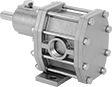
Constant-Flow-Rate Gear Pumps for Oil
 |
A high-horsepower motor moves oil with a viscosity similar to SAE 60 motor oil. These gear pumps produce a smooth flow of liquid to lubricate equipment and blend oils. Motor is open dripproof (ODP) for use in clean, dry, and well-ventilated environments. Pumps are gravity fed and require an elevated liquid source to fully fill the pump before turning on. Do not run dry or use with solids.
Note: If flow control is needed, place valves or reducers on the discharge side; never restrict the inlet of a pump with a valve or reducer.
Cannot Be Sold Outside North America—Products cannot be sold outside North America due to restrictions.
Intake (NPT) | Discharge (NPT) | Overall | ||||||||||||||||||
|---|---|---|---|---|---|---|---|---|---|---|---|---|---|---|---|---|---|---|---|---|
Max. Flow Rate | Max. ft. of Head, ft. | Max. Pressure, psi | Max. Viscosity, cP | Temp. Range, ° F | Power, hp | Current | Pipe Size | Connection | Gender | Pipe Size | Connection | Gender | Lg. | Wd. | Ht. | Cannot Be Sold To | Each | |||
240V AC/460V AC, Three Phase—Without Thermal Overload Protection | ||||||||||||||||||||
Hardwire | ||||||||||||||||||||
| 5 gpm | 577 | 250 | 880 | -20 to 240 | 1/2 | 2 amp/1 amp | 1/2 | Threaded | Female | 1/2 | Threaded | Female | 21 5/8" | 6 7/8" | 8 1/2" | Outside North America | 41505K41 | 000000000 | ||
208V AC to 240V AC/460V AC, Three Phase—Without Thermal Overload Protection | ||||||||||||||||||||
Hardwire | ||||||||||||||||||||
| 10 gpm | 577 | 250 | 880 | -20 to 240 | 2 | 6.2 amp/3.1 amp | 3/4 | Threaded | Female | 3/4 | Threaded | Female | 24" | 6 7/8" | 8 1/2" | Outside North America | 41505K43 | 00000000 | ||
| 20 gpm | 577 | 250 | 880 | -20 to 240 | 2 | 6.2 amp/3.1 amp | 1 | Threaded | Female | 1 | Threaded | Female | 24 1/2" | 6 7/8" | 8 1/2" | Outside North America | 41505K45 | 00000000 | ||
| 30 gpm | 577 | 250 | 880 | -20 to 240 | 3 | 8.2 amp/4.1 amp | 1 | Threaded | Female | 1 | Threaded | Female | 25" | 6 7/8" | 8 1/2" | Outside North America | 41505K47 | 00000000 | ||
| 40 gpm | 577 | 250 | 880 | -20 to 240 | 5 | 13.8 amp/6.9 amp | 1 1/2 | Threaded | Female | 1 1/2 | Threaded | Female | 28 1/8" | 11 7/8" | 8 1/2" | Outside North America | 41505K49 | 00000000 | ||
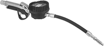
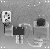
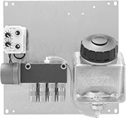
Metering Container-Mount Oil Dispensers
 |  |
Drum Not Included |
Equipped with a flowmeter/totalizer, this dispenser displays both flow rate and cumulative flow volume of the oil dispensed. Mount it to your drum of oil. It's smaller and more portable than air-powered container-mount dispensers, making it good for refilling gear boxes and transmissions. The container is not included.
For Container | For Max. Viscosity | |||||||||||||||||
|---|---|---|---|---|---|---|---|---|---|---|---|---|---|---|---|---|---|---|
Size, gal. | Max. Dia. | Max. Ht. | oz. per Stroke, fl. oz. | Oil Outlet Hose Lg., ft. | Max. Oil Outlet Pressure | Material | Measurement Unit | Max. No. Displayed | Batteries Included | ISO Grade | SAE Grade | SSU Grade, SSU | AGMA Grade | Includes | Each | |||
| 16 | 15" | 30" | 8 | 6 | Not Rated | Aluminum, Steel | Pints, Quarts, Liters, Gallons | 9,999 | Yes | 460 | 140 | 7,750 | 7 | Pump, Cover, Curved Nozzle, Dolly, Meter, Oil Outlet Hose | 1318K11 | 0000000 | ||
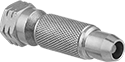
Design-Your-Own Sealed Dispensers
Pumps for Screw-On Cap
 |  |
Pump | Heavy Duty |
Pumps | Replacement Repair Kits | |||||||||||||||||
|---|---|---|---|---|---|---|---|---|---|---|---|---|---|---|---|---|---|---|
Nozzle | Outlet | Inlet | Hose | |||||||||||||||
Duty Rating | Max. Viscosity, cP | Flow Rate, fl oz/stroke | OD | Material | Seal Material | Pipe Size | Gender | Pipe Size | Gender | Lg., ft. | Material | Reinforcement Material | Max. Temp., ° F | Each | Each | |||
| — | 400 | 2.8 | 1/2" | Aluminum | Buna-N | 1/4 | Male | — | — | 5 | PVC | 304 Stainless Steel | 175 | 5199T63 | 0000000 | 5199T81 | 00000 | |
| Heavy | 600 | 2.8 | 1/2" | Aluminum | Viton® Fluoroelastomer | 1/4 | Male | 1/4 | Male | 5 | PVC | 304 Stainless Steel | 175 | 5199T21 | 000000 | 5199T82 | 00000 | |
 |  |
With Nozzle | With Threaded Outlet |
Constant-Flow-Rate Gear Pumps without Motor for Oil
 |
A cast iron housing and steel gears allow these gear pumps to be used to dispense oil and fuel such as hydraulic oil and diesel fuel. Select your own motor to tailor them to your application. Use an air or electric motor with a coupling and belt/pulley drive. They produce a smooth flow of liquid for applications such as engine lubrication. All are self-priming, which means they create a suction force to draw liquid upward and fill the pump chamber. Do not use with solids.
Note: Pumps must be filled with liquid before use. They need a constant flow of liquid and cannot run dry.
Required hp, hp | Intake (NPT) | Discharge (NPT) | Overall | Shaft | |||||||||||||||||||
|---|---|---|---|---|---|---|---|---|---|---|---|---|---|---|---|---|---|---|---|---|---|---|---|
Max. Flow Rate @ 25 psi, gpm | Max. Flow Rate | Max. ft. of Head, ft. | Max. Pressure, psi | Max. Viscosity, cP | Temp. Range, ° F | @ 25 psi | @ 100 psi | Pipe Size | Connection | Gender | Pipe Size | Connection | Gender | Lg. | Wd. | Ht. | Dia. | Lg. | Ctr.-to-Base Lg. | Each | |||
For 1,725 rpm Maximum Motor Speed | |||||||||||||||||||||||
| 8.9 | 9 gpm | 462 | 200 | 20,000 | -20 to 400 | 3/4 | 1 | 1/2 | Threaded | Female | 1/2 | Threaded | Female | 7 1/4" | 3 7/16" | 4 1/2" | 5/8" | 1 9/16" | 3" | 41915K72 | 000000000 | ||
Compact Constant-Flow-Rate Gear Pumps for Water and Oil
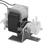 |
Designed to fit into small equipment, these pumps have miniature gears and a fractional horsepower motor for low-flow applications. Pumps are gravity fed and require an elevated liquid source to fully fill the pump before turning on. Do not run dry or use with solids.
Note: If flow control is needed, place valves or reducers on the discharge side; never restrict the inlet of a pump with a valve or reducer
Intake (NPT) | Discharge (NPT) | Overall | |||||||||||||||||
|---|---|---|---|---|---|---|---|---|---|---|---|---|---|---|---|---|---|---|---|
Max. Flow Rate | Max. ft. of Head, ft. | Max. Pressure, psi | Max. Viscosity, cP | Temp. Range, ° F | Power | Current | Connection | Gender | For Tube ID | Connection | Gender | For Tube ID | Lg. | Wd. | Ht. | Each | |||
120V AC, Single Phase—With Thermal Overload Protection | |||||||||||||||||||
Hardwire | |||||||||||||||||||
| 0.43 gpm (55 fl oz/min) | 28 | 20 | 800 | 10 to 180 | Fractional | 1.5 amp | Barbed | Male | 3/16" | Barbed | Male | 3/16" | 4 3/8" | 3" | 3 3/4" | 8220K41 | 0000000 | ||
240V AC, Single Phase—With Thermal Overload Protection | |||||||||||||||||||
Hardwire | |||||||||||||||||||
| 0.43 gpm (55 fl oz/min) | 28 | 20 | 800 | 10 to 180 | Fractional | 1.5 amp | Barbed | Male | 3/16" | Barbed | Male | 3/16" | 4 3/8" | 3" | 3 3/4" | 8220K42 | 000000 | ||
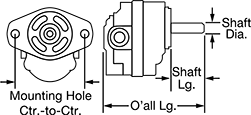
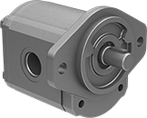
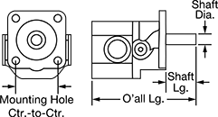
Hydraulic Gear Pumps
SAE AA—3 1/4" Mounting Hole Center-to-Center
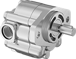 |  |
UN/UNF (SAE Straight) Thread—UN/UNF (SAE Straight) thread connections have straight threads and are also known as O-ring Boss fittings.
Inlet Connection | Outlet Connection | Overall | Shaft | |||||||||||||||
|---|---|---|---|---|---|---|---|---|---|---|---|---|---|---|---|---|---|---|
Fixed Displacement Rate, in³/rev | Max. Flow Rate | Max. Pressure, psi | Max. Rotation Speed, rpm | Thread Size | Thread Type | Dash Size | Thread Size | Thread Type | Dash Size | Lg. | Ht. | Dia. | Lg. | Choose a Drive Direction | Each | |||
| 0.11 | 1.7 gpm | 2,500 | 4,000 | 7/8"-14 | UN/UNF (SAE Straight) | 10 | 3/4"-16 | UN/UNF (SAE Straight) | 08 | 4" | 3 5/8" | 1/2" | 1 1/4" | Clockwise, Counterclockwise | 6296K44 | 0000000 | ||
| 0.21 | 3.3 gpm | 2,500 | 4,000 | 7/8"-14 | UN/UNF (SAE Straight) | 10 | 3/4"-16 | UN/UNF (SAE Straight) | 08 | 4 1/4" | 3 5/8" | 1/2" | 1 1/4" | Clockwise, Counterclockwise | 6296K45 | 000000 | ||
| 0.33 | 5.2 gpm | 2,500 | 4,000 | 7/8"-14 | UN/UNF (SAE Straight) | 10 | 3/4"-16 | UN/UNF (SAE Straight) | 08 | 4 3/8" | 3 5/8" | 1/2" | 1 1/4" | Clockwise, Counterclockwise | 6296K47 | 000000 | ||
| 0.52 | 8.4 gpm | 2,500 | 4,000 | 7/8"-14 | UN/UNF (SAE Straight) | 10 | 3/4"-16 | UN/UNF (SAE Straight) | 08 | 4 3/4" | 3 5/8" | 1/2" | 1 1/4" | Clockwise, Counterclockwise | 6296K53 | 000000 | ||
| 0.64 | 7.8 gpm | 2,000 | 3,000 | 7/8"-14 | UN/UNF (SAE Straight) | 10 | 3/4"-16 | UN/UNF (SAE Straight) | 08 | 4 7/8" | 3 5/8" | 1/2" | 1 1/4" | Clockwise, Counterclockwise | 6296K55 | 000000 | ||
SAE A—4 3/16" Mounting Hole Center-to-Center
 | |
UN/UNF (SAE Straight) Thread—UN/UNF (SAE Straight) thread connections have straight threads and are also known as O-ring Boss fittings.
Inlet Connection | Outlet Connection | Overall | Shaft | |||||||||||||||
|---|---|---|---|---|---|---|---|---|---|---|---|---|---|---|---|---|---|---|
Fixed Displacement Rate, in³/rev | Max. Flow Rate | Max. Pressure, psi | Max. Rotation Speed, rpm | Thread Size | Thread Type | Dash Size | Thread Size | Thread Type | Dash Size | Lg. | Ht. | Dia. | Lg. | Choose a Drive Direction | Each | |||
| 0.37 | 5.9 gpm | 4,000 | 4,000 | 7/8"-14 | UN/UNF (SAE Straight) | 10 | 3/4"-16 | UN/UNF (SAE Straight) | 08 | 4 7/8" | 4 5/8" | 3/4" | 1" | Clockwise, Counterclockwise | 6296K25 | 0000000 | ||
| 0.49 | 7.9 gpm | 4,000 | 4,000 | 1 1/16"-12 | UN/UNF (SAE Straight) | 12 | 7/8"-14 | UN/UNF (SAE Straight) | 10 | 5" | 4 5/8" | 3/4" | 1" | Clockwise, Counterclockwise | 6296K26 | 000000 | ||
| 0.61 | 9.9 gpm | 4,000 | 4,000 | 1 1/16"-12 | UN/UNF (SAE Straight) | 12 | 7/8"-14 | UN/UNF (SAE Straight) | 10 | 5 1/8" | 4 5/8" | 3/4" | 1" | Clockwise, Counterclockwise | 6296K27 | 000000 | ||
| 0.98 | 11.9 gpm | 4,000 | 3,000 | 1 1/16"-12 | UN/UNF (SAE Straight) | 12 | 7/8"-14 | UN/UNF (SAE Straight) | 10 | 5 1/2" | 4 5/8" | 3/4" | 1" | Clockwise, Counterclockwise | 6296K28 | 000000 | ||
| 1.16 | 14.1 gpm | 4,000 | 3,000 | 1 5/16"-12 | UN/UNF (SAE Straight) | 16 | 1 1/16"-12 | UN/UNF (SAE Straight) | 12 | 5 5/8" | 4 5/8" | 3/4" | 1" | Clockwise, Counterclockwise | 6296K29 | 000000 | ||
| 1.4 | 15.9 gpm | 3,200 | 2,800 | 1 5/16"-12 | UN/UNF (SAE Straight) | 16 | 1 1/16"-12 | UN/UNF (SAE Straight) | 12 | 5 7/8" | 4 5/8" | 3/4" | 1" | Clockwise, Counterclockwise | 6296K37 | 000000 | ||
| 1.65 | 16.1 gpm | 2,700 | 2,400 | 1 5/16"-12 | UN/UNF (SAE Straight) | 16 | 1 1/16"-12 | UN/UNF (SAE Straight) | 12 | 6 1/8" | 4 5/8" | 3/4" | 1" | Clockwise, Counterclockwise | 6296K38 | 000000 | ||
SAE B—5 3/4" Mounting Hole Center-to-Center
 | |
UN/UNF (SAE Straight) Thread—UN/UNF (SAE Straight) thread connections have straight threads and are also known as O-ring Boss fittings.
Inlet Connection | Outlet Connection | Overall | Shaft | |||||||||||||||
|---|---|---|---|---|---|---|---|---|---|---|---|---|---|---|---|---|---|---|
Fixed Displacement Rate, in³/rev | Max. Flow Rate | Max. Pressure, psi | Max. Rotation Speed, rpm | Thread Size | Thread Type | Dash Size | Thread Size | Thread Type | Dash Size | Lg. | Ht. | Dia. | Lg. | Choose a Drive Direction | Each | |||
| 2.01 | 24.5 gpm | 4,000 | 3,000 | 1 5/8"-12 | UN/UNF (SAE Straight) | 20 | 1 5/16"-12 | UN/UNF (SAE Straight) | 16 | 7 1/8" | 5 7/8" | 7/8" | 1 1/4" | Clockwise, Counterclockwise | 6296K39 | 0000000 | ||
| 2.32 | 28.3 gpm | 4,000 | 3,000 | 1 5/8"-12 | UN/UNF (SAE Straight) | 20 | 1 5/16"-12 | UN/UNF (SAE Straight) | 16 | 7 3/8" | 5 7/8" | 7/8" | 1 1/4" | Clockwise | 6296K73 | 000000 | ||
| 3.05 | 33.5 gpm | 2,900 | 2,700 | 1 5/8"-12 | UN/UNF (SAE Straight) | 20 | 1 5/16"-12 | UN/UNF (SAE Straight) | 16 | 7 3/4" | 5 7/8" | 7/8" | 1 1/4" | Clockwise, Counterclockwise | 6296K59 | 000000 | ||
SAE 4F17—2" Mounting Hole Center-to-Center
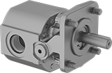 |  |
Inlet Connection | Outlet Connection | Overall | Shaft | |||||||||||||||
|---|---|---|---|---|---|---|---|---|---|---|---|---|---|---|---|---|---|---|
Fixed Displacement Rate, in³/rev | Max. Flow Rate | Max. Pressure, psi | Max. Rotation Speed, rpm | Thread Size | Thread Type | Dash Size | Thread Size | Thread Type | Dash Size | Lg. | Ht. | Dia. | Lg. | Drive Direction | Each | |||
| 0.07 | 0.8 gpm | 3,000 | 4,000 | 9/16"-18 | UN/UNF (SAE Straight) | 06 | 9/16"-18 | UN/UNF (SAE Straight) | 06 | 4 5/8" | 3 7/16" | 1/2" | 1 3/8" | Clockwise, Counterclockwise | 6296K51 | 0000000 | ||
| 0.13 | 1.7 gpm | 3,000 | 4,000 | 3/4"-16 | UN/UNF (SAE Straight) | 08 | 3/4"-16 | UN/UNF (SAE Straight) | 08 | 4 5/8" | 3 7/16" | 1/2" | 1 3/8" | Clockwise, Counterclockwise | 6296K71 | 000000 | ||
| 0.39 | 5 gpm | 3,000 | 4,000 | 7/8"-14 | UN/UNF (SAE Straight) | 10 | 7/8"-14 | UN/UNF (SAE Straight) | 10 | 5 1/8" | 3 7/16" | 1/2" | 1 3/8" | Clockwise, Counterclockwise | 6296K54 | 000000 | ||
| 0.71 | 5.4 gpm | 1,800 | 2,400 | 7/8"-14 | UN/UNF (SAE Straight) | 10 | 7/8"-14 | UN/UNF (SAE Straight) | 10 | 5 5/8" | 3 7/16" | 1/2" | 1 3/8" | Clockwise, Counterclockwise | 6296K56 | 000000 | ||
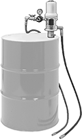
Air-Powered Container-Mount Oil Dispensers
 |
Drum Not Included |
Driven by an air-powered pump, this dispenser comes with an adapter to mount through a bung opening on a drum of oil (not included).
Air Inlet | For Max. Viscosity | ||||||||||||||||
|---|---|---|---|---|---|---|---|---|---|---|---|---|---|---|---|---|---|
For Container Size, gal. | Flow Rate, gpm | Max. Oil Outlet Pressure, psi | Oil Outlet Hose Lg., ft. | Material | Pressure, psi | Hose Lg., ft. | Thread Type | Pipe Size | Gender | ISO Grade | SAE Grade | SSU Grade, SSU | AGMA Grade | Includes | Each | ||
| 55 | 1.8 | 540 | 6 | Aluminum | 40 to 180 | 6 | NPT | 3/8 | Female | 1500 | 250 | 9,000 | 8 | Bung Adapter with a 2 NPT Male Connection, Pump, Air Inlet Hose, Air Pressure Regulator with Gauge, Oil Outlet Hose | 2332K5 | 000000000 | |
Constant-Flow-Rate Gear Pumps without Motor for Chemicals
 |
With a 316 stainless steel housing and stainless steel gears, these gear pumps are often used to dispense chemicals such as ethylene glycol, isopropyl alcohol, and nitric acid. Use an electric motor with a coupling and belt/pulley drive. They produce a smooth flow of liquid. All are self-priming, which means they create a suction force to draw liquid upward and fill the pump chamber. Do not use with solids.
Required hp, hp | Intake (NPT) | Discharge (NPT) | Overall | Shaft | |||||||||||||||||||
|---|---|---|---|---|---|---|---|---|---|---|---|---|---|---|---|---|---|---|---|---|---|---|---|
Max. Flow Rate @ 25 psi, gpm | Max. Flow Rate | Max. ft. of Head, ft. | Max. Pressure, psi | Max. Viscosity, cP | Temp. Range, ° F | @ 25 psi | @ 100 psi | Pipe Size | Connection | Gender | Pipe Size | Connection | Gender | Lg. | Wd. | Ht. | Dia. | Lg. | Ctr.-to-Base Lg. | Each | |||
For 1,800 rpm Maximum Motor Speed | |||||||||||||||||||||||
| 4.3 | 4 gpm | 346.3 | 150 | 20,000 | -50 to 450 | 1/4 | 3/4 | 1/2 | Threaded | Female | 1/2 | Threaded | Female | 6 1/4" | 3" | 3 3/4" | 1/2" | 1 1/4" | 2 5/8" | 43095K47 | 000000000 | ||
| 10.2 | 10 gpm | 346.3 | 150 | 20,000 | -50 to 450 | 1/2 | 1 1/2 | 3/4 | Threaded | Female | 3/4 | Threaded | Female | 7 1/2" | 3 3/8" | 4 3/8" | 5/8" | 1 3/4" | 3" | 43095K52 | 00000000 | ||
Harsh-Environment Compact Constant-Flow-Rate Gear Pumps for Water and Oil
 |
An aluminum enclosure around the motor provides protection in dusty and dirty environments. Designed to fit into small equipment, these pumps have miniature gears and a fractional horsepower motor for low-flow applications. Pumps are gravity fed and require an elevated liquid source to fully fill the pump before turning on. Do not run dry or use with solids.
Note: If flow control is needed, place valves or reducers on the discharge side; never restrict the inlet of a pump with a valve or reducer.
Intake (NPT) | Discharge (NPT) | Overall | |||||||||||||||||
|---|---|---|---|---|---|---|---|---|---|---|---|---|---|---|---|---|---|---|---|
Max. Flow Rate | Max. ft. of Head, ft. | Max. Pressure, psi | Max. Viscosity, cP | Temp. Range, ° F | Power | Current | Connection | Gender | For Tube ID | Connection | Gender | For Tube ID | Lg. | Wd. | Ht. | Each | |||
12V DC—Without Thermal Overload Protection | |||||||||||||||||||
Hardwire | |||||||||||||||||||
| 0.61 gpm (78 fl oz/min) | 46 | 20 | 800 | 10 to 180 | Fractional | 2.2 amp | Barbed | Male | 3/16" | Barbed | Male | 3/16" | 4" | 1 3/4" | 2 1/2" | 8220K43 | 000000 | ||
24V DC—Without Thermal Overload Protection | |||||||||||||||||||
Hardwire | |||||||||||||||||||
| 0.61 gpm (78 fl oz/min) | 46 | 20 | 800 | 10 to 180 | Fractional | 1.4 amp | Barbed | Male | 3/16" | Barbed | Male | 3/16" | 4" | 1 3/4" | 2 1/2" | 8220K44 | 00000 | ||
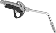
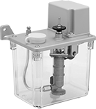
Manual Oil-Dispensing Pumps
 |  |  |
Vertical | Horizontal with Left Side Handle | Horizontal with Right Side Handle |
Dispense a fixed amount of oil by pumping the handle. To control flow to multiple lubrication points, use metering valves (sold separately).
Vertical Mount—Vertical-mount pumps dispense oil when you pull the handle.
Horizontal Mount—Horizontal-mount pumps dispense oil when you release the handle.
Overall | Mounting | For Max. Viscosity | ||||||||||||||||
|---|---|---|---|---|---|---|---|---|---|---|---|---|---|---|---|---|---|---|
No. of Pumps | Cap., fl. oz. | oz. per Cycle, fl. oz. | Max. Oil Outlet Pressure, psi | Reservoir Material | Ht. | Wd. | Dp. | Temp. Range, ° F | Hole Dia. | Fasteners Included | ISO Grade | SAE Grade | SSU Grade, SSU | AGMA Grade | Each | |||
Oil-Dispensing Pumps with Vertical Mount and Bottom Handle | ||||||||||||||||||
5/16"-24 UNF Female Oil Outlet | ||||||||||||||||||
| 1 | 15 | 0.27 | 200 | Aluminum | 7 7/8" | 3 15/16" | 5 15/16" | 32 to 120 | 1/4" | No | 150 | 40 | 700 | 4 | 2287K1 | 0000000 | ||
Oil-Dispensing Pumps with Horizontal Mount and Left-Side Handle | ||||||||||||||||||
5/16"-24 UNF Female Oil Outlet | ||||||||||||||||||
| 1 | 19 | 0.27 | 50 | Aluminum | 5" | 3 3/16" | 9 1/4" | 32 to 120 | 1/4" | No | 150 | 40 | 700 | 4 | 2287K8 | 000000 | ||
Oil-Dispensing Pumps with Horizontal Mount and Right-Side Handle | ||||||||||||||||||
5/16"-24 UNF Female Oil Outlet | ||||||||||||||||||
| 1 | 19 | 0.27 | 50 | Aluminum | 5" | 3 3/16" | 9 1/4" | 32 to 120 | 1/4" | No | 150 | 40 | 700 | 4 | 2287K9 | 000000 | ||
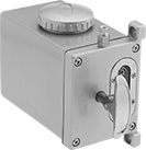
Adjustable-Interval Electric Oil-Dispensing Pumps
 |
Set the cycle interval as well as the dispensing duration. This pump has a maximum flow of 0.1 oz. per second. It has a low-level switch that triggers an audible alarm and can be wired to additional, external alarms.
Use metering valves (sold separately) to adjust the flow of oil to multiple lubrication points.
Overall | Mounting | For Max. Viscosity | ||||||||||||||||||||
|---|---|---|---|---|---|---|---|---|---|---|---|---|---|---|---|---|---|---|---|---|---|---|
No. of Pumps | Cap., qt. | Flow Duration, sec. | Flow Rate, fl oz/sec | Dispensing Interval, min. | Max. Oil Outlet Pressure, psi | Reservoir Material | Ht. | Wd. | Dp. | Voltage, V AC | Current, amp | Temp. Range, ° F | Hole Dia. | Fasteners Included | ISO Grade | SAE Grade | SSU Grade, SSU | AGMA Grade | Each | |||
5/16"-24 UNF Female Oil Outlet | ||||||||||||||||||||||
| 1 | 3 1/8 | 1 to 180 | 0.1 | 3 to 999 | 100 | Plastic | 10 1/16" | 8 7/8" | 6 11/16" | 120 | 0.03 | 32 to 120 | 1/4" | No | 150 | 40 | 700 | 4 | 2287K4 | 000000000 | ||
Drum Faucets for Oil-Dispensing Stations
 |
Add faucets to oil dispensing stations for increased utility.
Oil Inlet | For Max. Viscosity | ||||||||||||||
|---|---|---|---|---|---|---|---|---|---|---|---|---|---|---|---|
Flow Rate, gpm | Thread Type | Pipe Size | Gender | Overall Ht. | Projection | Material | Mounting Hardware Included | ISO Grade | SAE Grade | SSU Grade, SSU | AGMA Grade | Each | |||
| 1.5 | NPT | 3/4 | Male | 5 5/8" | 5 5/8" | Stainless Steel, Steel | Yes | 460 | 140 | 7,750 | 7 | 1941N12 | 0000000 | ||
Grease Gun Filler Pumps
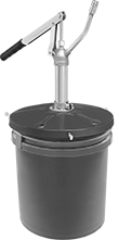 |
Mount these pumps to your grease container to bulk load guns. Insert the filler nipple into the socket located on top of the unit, then pump the lever handle. Pumps include a follower plate that moves down the inside of the container as the grease level drops to compress the grease and prevent vapor pockets. Container not included.
For 25 lb. to 50 lb. Pail
Grease Gun Filler Pumps | Replacement Grease Gun Filler Nipples | |||||||||||||
|---|---|---|---|---|---|---|---|---|---|---|---|---|---|---|
For Container | Nozzle Connection | |||||||||||||
Max. Ht. | Max. Dia. | For Filler Nipple Mfr. | For NLGI Consistency Grade | oz. per Stroke, fl. oz. | Thread Type | Pipe Size | Gender | Material | Includes | Each | Each | |||
| 24" | 12 1/8" | Lincoln | 0, 1, 2 | 1 | NPT | 1/4 | Female | Steel | Follower Plate, Cover, Pump | 1014K25 | 000000 | 1014K31 | 000000 | |
For 35 lb. Pail
Grease Gun Filler Pumps | Replacement Grease Gun Filler Nipples | Replacement Follower Plates | ||||||||||||||
|---|---|---|---|---|---|---|---|---|---|---|---|---|---|---|---|---|
For Container | Nozzle Connection | |||||||||||||||
Max. Ht. | Max. Dia. | For Filler Nipple Mfr. | For NLGI Consistency Grade | oz. per Stroke, fl. oz. | Thread Type | Pipe Size | Gender | Material | Includes | Each | Each | Each | ||||
| 13 1/4" | 12" | Alemite | 000, 00, 0, 1, 2 | 1 | NPT | 1/4 | Male | Steel | Alemite Filler Nipple, Follower Plate, Cover, Pump | 1014K21 | 0000000 | 1014K31 | 000000 | ——— | 0 | |
| 24" | 11 1/8" | Alemite | 000, 00, 0, 1, 2 | 2.7 | NPT | 3/8 | Female | Steel | Alemite Filler Nipple, Follower Plate, Cover, Pump | 1014K23 | 000000 | ——— | 0 | 1014K235 | 0000000 | |
For 120 lb. Drum
Grease Gun Filler Pumps | Replacement Grease Gun Filler Nipples | |||||||||||||
|---|---|---|---|---|---|---|---|---|---|---|---|---|---|---|
For Container | Nozzle Connection | |||||||||||||
Max. Ht. | Max. Dia. | For Filler Nipple Mfr. | For NLGI Consistency Grade | oz. per Stroke, fl. oz. | Thread Type | Pipe Size | Gender | Material | Includes | Each | Each | |||
| 27" | 15" | Alemite | 000, 00, 0, 1, 2 | 2.6 | NPT | 3/8 | Female | Steel | Alemite Filler Nipple, Follower Plate, Cover, Pump | 1008K25 | 0000000 | 1014K31 | 000000 | |
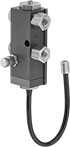
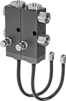
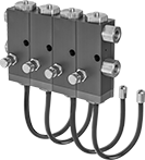
Air-Powered Oil-Dispensing Pumps
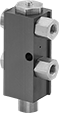 | 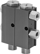 | 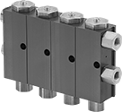 | 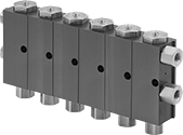 |
1 Pump | 2 Pumps | 4 Pumps | 6 Pumps |
 |  |  | |
1 Pump with Spray Nozzle | 2 Pumps with Spray Nozzle | 4 Pumps with Spray Nozzle |
Oil Inlet | Overall | Air Inlet | Mounting | For Max. Viscosity | |||||||||||||||||||||
|---|---|---|---|---|---|---|---|---|---|---|---|---|---|---|---|---|---|---|---|---|---|---|---|---|---|
No. of Pumps | oz. per Cycle, fl. oz. | Dispensing Interval, sec. | Max. Oil Outlet Pressure, psi | Pump Material | Thread Type | Pipe Size | Gender | Ht. | Wd. | Dp. | Air Inlet Pressure, psi | Thread Type | Pipe Size | Gender | Temp. Range, ° F | Hole Dia. | Fasteners Included | ISO Grade | SAE Grade | SSU Grade, SSU | AGMA Grade | Each | |||
Oil-Dispensing Pumps | |||||||||||||||||||||||||
1/8 NPT Female Oil Outlets | |||||||||||||||||||||||||
| 1 | 0 to 0.007 | 0.5 to 1 | 1,080 | Aluminum | NPT | 1/8 | Female | 4" | 2" | 1 1/8" | 40 to 120 | NPT | 1/8 | Female | -15 to 180 | 9/32" | No | 220 | 90 | 1,000 | 5 | 2279K51 | 0000000 | ||
| 2 | 0 to 0.007 | 0.5 to 1 | 1,080 | Aluminum | NPT | 1/8 | Female | 4" | 3 1/4" | 1 1/8" | 40 to 120 | NPT | 1/8 | Female | -15 to 180 | 9/32" | No | 220 | 90 | 1,000 | 5 | 2279K52 | 000000 | ||
| 4 | 0 to 0.007 | 0.5 to 1 | 1,080 | Aluminum | NPT | 1/8 | Female | 4" | 5 3/4" | 1 1/8" | 40 to 120 | NPT | 1/8 | Female | -15 to 180 | 9/32" | No | 220 | 90 | 1,000 | 5 | 2279K53 | 000000 | ||
| 6 | 0 to 0.007 | 0.5 to 1 | 1,080 | Aluminum | NPT | 1/8 | Female | 4" | 8 1/4" | 1 1/8" | 40 to 120 | NPT | 1/8 | Female | -15 to 180 | 9/32" | No | 220 | 90 | 1,000 | 5 | 2279K54 | 000000 | ||
Oil-Dispensing Pumps with Spray Nozzle | |||||||||||||||||||||||||
1/8 NPT Female Oil Outlets | |||||||||||||||||||||||||
| 1 | 0 to 0.007 | 0.5 to 1 | 1,080 | Aluminum | NPT | 1/8 | Female | 4" | 2" | 1 1/8" | 40 to 120 | NPT | 1/8 | Female | -15 to 180 | 9/32" | No | 220 | 90 | 1,000 | 5 | 2279K41 | 000000 | ||
| 2 | 0 to 0.007 | 0.5 to 1 | 1,080 | Aluminum | NPT | 1/8 | Female | 4" | 3 1/4" | 1 1/8" | 40 to 120 | NPT | 1/8 | Female | -15 to 180 | 9/32" | No | 220 | 90 | 1,000 | 5 | 2279K42 | 000000 | ||
| 4 | 0 to 0.007 | 0.5 to 1 | 1,080 | Aluminum | NPT | 1/8 | Female | 4" | 5 3/4" | 1 1/8" | 40 to 120 | NPT | 1/8 | Female | -15 to 180 | 9/32" | No | 220 | 90 | 1,000 | 5 | 2279K43 | 000000 | ||
Oil Dispensing Stations
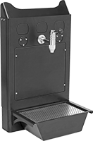 |
Connect these dispensing stations to your bulk oil container to easily fill hand-held dispensers. They include one faucet and can fit up to three, so you can access different types of oil at a single centralized point.
Overall | For Max. Viscocity | |||||||||||||||
|---|---|---|---|---|---|---|---|---|---|---|---|---|---|---|---|---|
For Max. Container Ht. | Flow Rate, gpm | Ht. | Wd. | Dp. | No. of Faucet Knockouts | Faucet Mounting Hardware Included | Material | ISO Grade | SAE Grade | SSU Grade, SSU | AGMA Grade | Features | Each | |||
Stations with One Faucet | ||||||||||||||||
| 14 7/8" | 1.5 | 32 5/8" | 19 3/4" | 10 3/4" | 3 | Yes | Steel | 460 | 140 | 7,750 | 7 | Knockouts for Digital Meters, Removable Drip Tray | 1941N11 | 0000000 | ||
|
Oil Inlet | ||||||||||
|---|---|---|---|---|---|---|---|---|---|---|
Flow Rate, gpm | Thread Type | Pipe Size | Gender | Overall Ht. | Projection | Material | Mounting Hardware Included | Each | ||
| 1.5 | NPT | 3/4 | Male | 5 5/8" | 5 5/8" | Stainless Steel, Steel | Yes | 1941N12 | 0000000 | |
Metering Oil Dispenser Guns
 |  |  |
Rigid Nozzle | Flexible Nozzle | Dispensing Tip |
Guns | Gun Tips | |||||||||||||||||
|---|---|---|---|---|---|---|---|---|---|---|---|---|---|---|---|---|---|---|
Nozzle | Oil Inlet | |||||||||||||||||
Type | Lg. | Material | Flow Rate, gpm | Max. Oil Outlet Pressure, psi | Dispensing Tip Material | Thread Type | Pipe Size | Gender | Body Material | Measurement Unit | Max. No. Displayed | Batteries Included | For Max. AGMA Viscosity Grade | Each | Each | |||
| Rigid | 11" | Steel | 8 | 1,000 | Steel | NPT | 1/2 | Female | Aluminum | Quarts, Pints, Liters, Gallons | 999.99 | Yes | 7EP | 2254K33 | 0000000 | 2254K41 | 000000 | |
| Flexible | 12" | Steel | 8 | 1,000 | Steel | NPT | 1/2 | Female | Aluminum | Quarts, Pints, Liters, Gallons | 999.99 | Yes | 7EP | 2254K34 | 000000 | 2254K42 | 00000 | |
Oil Dispenser Guns
 |  | |
Rigid Nozzle | Flexible Nozzle | Dispensing Tip |
Guns | Gun Tips | |||||||||||||||||
|---|---|---|---|---|---|---|---|---|---|---|---|---|---|---|---|---|---|---|
Nozzle | Oil Inlet | For Maximum Viscosity | ||||||||||||||||
Type | Lg. | Material | Flow Rate, gpm | Max. Oil Outlet Pressure, psi | Dispensing Tip Material | Thread Type | Pipe Size | Gender | Body Material | ISO Grade | SAE Grade | SSU Grade, SSU | AGMA Grade | Each | Each | |||
| Rigid | 9 3/4" | Steel | 5 | 1,000 | Steel | NPT | 1/2 | Female | Aluminum | 460 | 140 | 1,800 | 7EP | 2254K11 | 0000000 | 2254K41 | 000000 | |
| Flexible | 14 3/4" | Buna-N | 5 | 1,000 | Steel | NPT | 1/2 | Female | Aluminum | 460 | 140 | 1,800 | 7EP | 2254K12 | 000000 | 2254K42 | 00000 | |
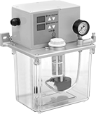
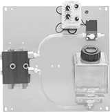
Precision Adjustable-Interval Electric Oil-Dispensing Pumps
 |  |
2 Pumps | 4 Pumps |
Panel | For Max. Viscosity | |||||||||||||||||||
|---|---|---|---|---|---|---|---|---|---|---|---|---|---|---|---|---|---|---|---|---|
No. of Pumps | Cap. | oz. per Cycle, fl. oz. | Dispensing Interval | Max. Oil Outlet Pressure, psi | Ht. | Wd. | Reservoir Material | Pump Material | Voltage, V AC | Current, amp | Temp. Range, ° F | Mounting Fasteners Included | ISO Grade | SAE Grade | SSU Grade, SSU | AGMA Grade | Each | |||
1/8 NPT Female Oil Outlets | ||||||||||||||||||||
| 2 | 16 fl. oz. | 0 to 0.005 | 1 min. to 24 hr. | 250 | 10 3/4" | 10 7/8" | Plastic | Aluminum | 120 | 0.06 | -15 to 120 | No | 220 | 90 | 1,000 | 5 | 2420K5 | 0000000 | ||
| 4 | 1 qt. | 0 to 0.005 | 1 min. to 24 hr. | 100 | 10 3/4" | 10 7/8" | Plastic | Aluminum | 120 | 0.06 | -15 to 120 | No | 220 | 90 | 1,000 | 5 | 2420K6 | 000000 | ||
Fixed-Interval Electric Oil-Dispensing Pumps
 |
Choose from pumps that dispense with a set interval. Turn the dial to adjust the flow from 0.1 oz. to 0.2 oz. per cycle. Pumps have a low-level switch that triggers an audible alarm and can be wired to additional, external alarms.
Use metering valves (sold separately) to adjust the flow of oil to multiple lubrication points.
Overall | Mounting | For Max. Viscosity | |||||||||||||||||||
|---|---|---|---|---|---|---|---|---|---|---|---|---|---|---|---|---|---|---|---|---|---|
No. of Pumps | Cap., qt. | oz. per Cycle, fl. oz. | Max. Oil Outlet Pressure, psi | Reservoir Material | Ht. | Wd. | Dp. | Voltage, V AC | Current, amp | Temp. Range, ° F | Hole Dia. | Fasteners Included | ISO Grade | SAE Grade | SSU Grade, SSU | AGMA Grade | Choose a Dispensing Interval, min. | Each | |||
5/16"-24 UNF Female Oil Outlet | |||||||||||||||||||||
| 1 | 2 1/8 | 0.1 to 0.2 | 40 | Plastic | 8 7/8" | 7 7/8" | 5 1/8" | 120 | 0.03 | 32 to 120 | 1/4" | No | 150 | 40 | 700 | 4 | 3, 5, 10, 15, 30, 60 | 2287K2 | 0000000 | ||
Air-Powered Oil-Dispensing Pump Systems
 | 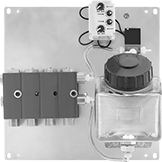 |
2 Pumps | 4 Pumps |
Ready to connect to your air system, these complete systems include a timer and a reservoir. Turn the dials to set the cycle interval. Each pump has a separate flow adjustment; use a screwdriver to turn the flow-adjustment screw. Pumps and their components come mounted on a panel.
Panel | For Max. Viscosity | ||||||||||||||||||||||
|---|---|---|---|---|---|---|---|---|---|---|---|---|---|---|---|---|---|---|---|---|---|---|---|
No. of Pumps | Cap. | oz. per Cycle, fl. oz. | Dispensing Interval | Max. Oil Outlet Pressure, psi | Ht. | Wd. | Reservoir Material | Pump Material | Air Inlet Pressure, psi | Air Inlet Gender | For Air Inlet Tube OD | Voltage, V AC | Current, amp | Temp. Range, ° F | Mounting Fasteners Included | ISO Grade | SAE Grade | SSU Grade, SSU | AGMA Grade | Each | |||
1/8 NPT Female Oil Outlets | |||||||||||||||||||||||
| 2 | 16 fl. oz. | 0 to 0.007 | 0.6 sec. to 24 hr. | 1,080 | 10 3/4" | 10 7/8" | Plastic | Aluminum | 40 to 120 | Female | 1/4" | 120 | 0.06 | -15 to 180 | No | 220 | 90 | 1,000 | 5 | 2420K1 | 0000000 | ||
| 4 | 1 qt. | 0 to 0.007 | 0.6 sec. to 24 hr. | 1,080 | 10 3/4" | 10 7/8" | Plastic | Aluminum | 40 to 120 | Female | 1/4" | 120 | 0.06 | -15 to 180 | No | 220 | 90 | 1,000 | 5 | 2420K2 | 000000 | ||
