Stabilize your carriages against pitch, roll, and yaw forces by installing them in pairs.
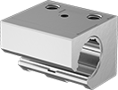
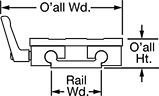
Extra-Wide Sleeve Bearing Carriages and Guide Rails

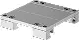
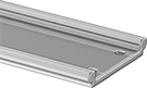
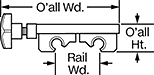
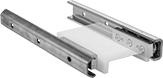
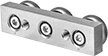
With a wide base and low-profile design, these carriages and guide rails stabilize moment (twisting) and off-center loads better than standard carriages and rails. Use in areas where multiple carriages or rails won't fit. Sleeve bearings allow them to outperform ball bearings in wet, dirty, and high-vibration environments. Mount in any orientation without affecting load capacity.
Aluminum carriages conduct and dissipate the heat produced by friction, protecting your machinery. They are more corrosion resistant than zinc carriages.
Zinc carriages are mildly corrosion resistant.
Aluminum Carriages and PTFE Plastic Bearings | |||||||||||||||
|---|---|---|---|---|---|---|---|---|---|---|---|---|---|---|---|
Mounting | Anodized Aluminum Guide Rails | ||||||||||||||
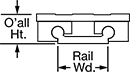
| For Rail Wd., mm | Static Load Cap., lbs. | O'all Ht., mm | Carriage Wd., mm | Carriage Lg., mm | Max. Temp., °F | No. of Holes | Hole Thread Size | Hole Thread Pitch, mm | Hole Dp., mm | Fasteners Included | Each | Rail Lengths, mm | Per mm | ||
Round | |||||||||||||||
| 40 | 1,050 | 24 | 73 | 100 | 190° | 4 | M6 | 1 | 19 | No | 6109K205 | 0000000 | 6109K42 | 00000 | |
| 40 | 1,050 | 24 | 73 | 150 | 190° | 4 | M6 | 1 | 19 | No | 6109K206 | 000000 | 6109K42 | 000 | |
| 40 | 1,050 | 24 | 73 | 200 | 190° | 4 | M6 | 1 | 19 | No | 6109K207 | 000000 | 6109K42 | 000 | |
Zinc Carriages and PTFE Plastic Bearings | |||||||||||||||
|---|---|---|---|---|---|---|---|---|---|---|---|---|---|---|---|
Mounting | Anodized Aluminum Guide Rails | ||||||||||||||
| For Rail Wd., mm | Static Load Cap., lbs. | O'all Ht., mm | Carriage Wd., mm | Carriage Lg., mm | Max. Temp., °F | No. of Holes | Hole Thread Size | Hole Thread Pitch, mm | Hole Dp., mm | Fasteners Included | Each | Rail Lengths, mm | Per mm | ||
Round | |||||||||||||||
| 40 | 1,050 | 24 | 73 | 100 | 190° | 4 | M6 | 1 | 19 | No | 6109K41 | 000000 | 6109K42 | 00000 | |
| 40 | 1,050 | 24 | 73 | 150 | 190° | 4 | M6 | 1 | 19 | No | 6109K203 | 00000 | 6109K42 | 000 | |
| 40 | 1,050 | 24 | 73 | 200 | 190° | 4 | M6 | 1 | 19 | No | 6109K204 | 00000 | 6109K42 | 000 | |
| For Carriage Wd., mm | For Rail Profile | Each | |
| 73, 107 | Round | 6109K273 | 00000 |
Locking Extra-Wide Sleeve Bearing Carriages and Guide Rails

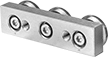
A handle on the side of the carriage locks the carriage in place. Carriages have a wide base for stabilizing moment (twisting) and off-center loads better than standard sleeve bearing carriages. Use them in areas where multiple carriages or rails won't fit. The sleeve bearings allow them to outperform ball bearings in wet, dirty, and high-vibration environments. Mount in any orientation without affecting load capacity.
Aluminum carriages conduct and dissipate the heat produced by friction, protecting your machinery. They are more corrosion resistant than zinc carriages.
Zinc carriages are mildly corrosion resistant.
Aluminum Carriages and PTFE Plastic Bearings | |||||||||||||||||||
|---|---|---|---|---|---|---|---|---|---|---|---|---|---|---|---|---|---|---|---|
Mounting | Anodized Aluminum Guide Rails | ||||||||||||||||||
| For Rail Wd., mm | Static Load Cap., lbs. | O'all Wd., mm | O'all Ht., mm | Carriage Wd., mm | Carriage Lg., mm | Handle Lg., mm | Max. Temp., °F | No. of Holes | Hole Thread Size | Hole Thread Pitch, mm | Hole Dp., mm | Fasteners Included | Rail Shape | Rail Shape | Each | Rail Lengths, mm | Per mm | ||
Round | |||||||||||||||||||
| 40 | 1,050 | 101 | 24 | 73 | 100 | 40 | 190° | 4 | M6 | 1 | 19 | No | Straight | Straight | 6109K261 | 0000000 | 6109K42 | 00000 | |
| 40 | 1,050 | 101 | 24 | 73 | 150 | 40 | 190° | 4 | M6 | 1 | 19 | No | Straight | Straight | 6109K262 | 000000 | 6109K42 | 000 | |
Zinc Carriages and PTFE Plastic Bearings | |||||||||||||||||||
|---|---|---|---|---|---|---|---|---|---|---|---|---|---|---|---|---|---|---|---|
Mounting | Anodized Aluminum Guide Rails | ||||||||||||||||||
| For Rail Wd., mm | Static Load Cap., lbs. | O'all Wd., mm | O'all Ht., mm | Carriage Wd., mm | Carriage Lg., mm | Handle Lg., mm | Max. Temp., °F | No. of Holes | Hole Thread Size | Hole Thread Pitch, mm | Hole Dp., mm | Fasteners Included | Rail Shape | Rail Shape | Each | Rail Lengths, mm | Per mm | ||
Round | |||||||||||||||||||
| 40 | 1,050 | 101 | 24 | 73 | 100 | 40 | 190° | 4 | M6 | 1 | 19 | No | Straight | Straight | 6109K121 | 0000000 | 6109K42 | 00000 | |
| 40 | 1,050 | 101 | 24 | 73 | 150 | 40 | 190° | 4 | M6 | 1 | 19 | No | Straight | Straight | 6109K258 | 000000 | 6109K42 | 000 | |
| 40 | 1,050 | 101 | 24 | 73 | 200 | 40 | 190° | 4 | M6 | 1 | 19 | No | Straight | Straight | 6109K259 | 000000 | 6109K42 | 000 | |
| For Carriage Wd., mm | For Rail Profile | Each | |
| 73, 107 | Round | 6109K273 | 00000 |
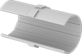
Low-Profile Sleeve Bearing Carriages and Guide Rails
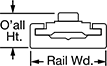
For applications with low clearance, these carriages protrude less than 5 mm above their rails. Use them for light to moderate loads, as well as frequent starting and stopping applications where tight tolerances are not required. Sleeve bearings allow them to outperform ball bearings in wet, dirty, and high-vibration environments. Mount in any orientation without affecting load capacity.
Zinc Carriages and PTFE Plastic Bearings | ||||||||||||||||
|---|---|---|---|---|---|---|---|---|---|---|---|---|---|---|---|---|
Mounting | Anodized Aluminum Guide Rails | |||||||||||||||
| For Rail Wd., mm | Static Load Cap., lbs. | O'all Ht., mm | Carriage Wd., mm | Carriage Lg., mm | Max. Temp., °F | No. of Holes | Hole Thread Size | Hole Thread Pitch, mm | Hole Dp., mm | Fasteners Included | Each | Rail Lengths, mm | Per mm | |||
| A | 40 | 150 | 9.5 | 34 | 50 | 190° | 2 | M4 | 0.7 | 8 | No | 6723K12 | 000000 | 6723K3 | 00000 | |
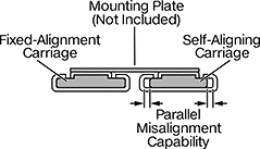
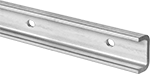
Self-Aligning Low-Profile Sleeve Bearing Carriages and Guide Rails
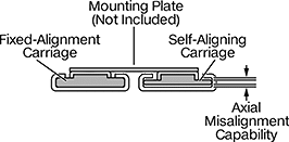
Compensate for rail misalignment in low-clearance applications with these carriages and guide rails. These carriages stick out less than 5 mm above their rails, giving them a low profile. They have a floating bearing that adjusts to correct misalignment between rails, so your carriages still move in tandem. Use them for light to moderate loads and applications with frequent starting and stopping where tight tolerances aren’t needed.
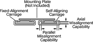
For a complete system, you’ll need a self-aligning carriage and rail on one side and a fixed-alignment carriage and rail on the other (all sold separately).
Carriages for axial rail misalignment compensate when the rails aren’t installed at the same exact height.
Carriages for parallel rail misalignment compensate when one rail is straight and the other is installed at a slight angle.
Carriages for axial/parallel rail misalignment compensate when the rails aren’t installed at the same exact height and also when one rail is straight while the other is installed at a slight angle.
Note: Each carriage can only be used with its corresponding guide rail. Load capacity is diminished when carriages are mounted upside down or on a vertical surface.
Zinc Carriages and PTFE Plastic Bearings | |||||||||||||||||
|---|---|---|---|---|---|---|---|---|---|---|---|---|---|---|---|---|---|
Mounting | Anodized Aluminum Guide Rails | ||||||||||||||||
| For Rail Wd., mm | Static Load Cap., lbs. | Axial Misalignment Capability, mm | O'all Ht., mm | Carriage Wd., mm | Carriage Lg., mm | Max. Temp., °F | No. of Holes | Hole Thread Size | Hole Thread Pitch, mm | Hole Dp., mm | Fasteners Included | Each | Rail Lengths, mm | Per mm | |||
| A | 40 | 150 | 0.4 | 9.5 | 34 | 50 | 120° | 2 | M4 | 0.7 | 6.1 | No | 4534N14 | 000000 | 6723K3 | 00000 | |
Zinc Carriages and PTFE Plastic Bearings | |||||||||||||||||
|---|---|---|---|---|---|---|---|---|---|---|---|---|---|---|---|---|---|
Mounting | Anodized Aluminum Guide Rails | ||||||||||||||||
| For Rail Wd., mm | Static Load Cap., lbs. | Parallel Misalignment Capability, mm | O'all Ht., mm | Carriage Wd., mm | Carriage Lg., mm | Max. Temp., °F | No. of Holes | Hole Thread Size | Hole Thread Pitch, mm | Hole Dp., mm | Fasteners Included | Each | Rail Lengths, mm | Per mm | |||
| A | 40 | 150 | 0.8 | 9.5 | 34 | 50 | 120° | 2 | M4 | 0.7 | 6.1 | No | 4534N15 | 000000 | 6723K3 | 00000 | |
Zinc Carriages and PTFE Plastic Bearings | ||||||||||||||||||
|---|---|---|---|---|---|---|---|---|---|---|---|---|---|---|---|---|---|---|
Misalignment Capability, mm | Mounting | Anodized Aluminum Guide Rails | ||||||||||||||||
| For Rail Wd., mm | Static Load Cap., lbs. | Axial | Parallel | O'all Ht., mm | Carriage Wd., mm | Carriage Lg., mm | Max. Temp., °F | No. of Holes | Hole Thread Size | Hole Thread Pitch, mm | Hole Dp., mm | Fasteners Included | Each | Rail Lengths, mm | Per mm | |||
| A | 40 | 150 | 0.4 | 0.8 | 9.5 | 34 | 50 | 120° | 2 | M4 | 0.7 | 6.1 | No | 4534N16 | 000000 | 6723K3 | 00000 | |
Carriages and PTFE Plastic Bearings | ||||||||||||||||
|---|---|---|---|---|---|---|---|---|---|---|---|---|---|---|---|---|
Mounting | Anodized Aluminum Guide Rails | |||||||||||||||
| For Rail Wd., mm | Static Load Cap., lbs. | O'all Ht., mm | Carriage Wd., mm | Carriage Lg., mm | Max. Temp., °F | No. of Holes | Hole Thread Size | Hole Thread Pitch, mm | Hole Dp., mm | Fasteners Included | Each | Rail Lengths, mm | Per mm | |||
Zinc Carriages | ||||||||||||||||
| A | 40 | 150 | 14.5 | 34 | 50 | 190° | 2 | M4 | 0.7 | 8 | No | 6723K12 | 000000 | 6723K3 | 00000 | |
Sleeve Bearing Carriages and Guide Rails for Curves


Build loops, circuits, and curved paths in assembly stations and other repetitive processes using these carriages and guide rails. They have a wide base, which means they stabilize twisting and off-center loads better than standard carriages and rails. They're useful in areas where multiple carriages and rails won’t fit. The carriages have sleeve bearings that swivel, so they move around curves without jamming. Their sleeve bearings also perform better in dirty, wet, and high-vibration environments than carriages with ball bearings. You can mount them in any orientation.
Aluminum Carriages and PTFE Plastic Bearings | 90° Angle Anodized Aluminum Guide Rails | U-Shape Anodized Aluminum Guide Rails | Round Anodized Aluminum Guide Rails | Straight Anodized Aluminum Guide Rails | ||||||||||||||
|---|---|---|---|---|---|---|---|---|---|---|---|---|---|---|---|---|---|---|
| For Rail Bend Radius, mm | Static Load Cap., lbs. | O'all Ht., mm | Carriage Wd., mm | Carriage Lg., mm | Each | Rail Length, mm | Each | Rail Length, mm | Each | Rail Length, mm | Each | Rail Lengths, mm | Per mm | |||||
For 40 mm Rail Width | ||||||||||||||||||
| 300 | 220 | 28 | 80 | 102 | 3938N17 | 0000000 | 671 | 3938N13 | 0000000 | 1,143 | 3938N15 | 0000000 | 1,883 | 3938N11 | 0000000 | 6109K42 | 00000 | |
| 500 | 220 | 28 | 80 | 102 | 3938N18 | 000000 | 985 | 3938N14 | 000000 | 1,771 | 3938N16 | 000000 | 3,140 | 3938N12 | 000000 | 6109K42 | 000 | |
Locking Sleeve Bearing Carriages and Guide Rails for Curves
A handle locks these carriages in place on curved paths, loops, and circuits in assembly stations and other repetitive processes. Because these carriages and rails have a wide base, they stabilize twisting and off-center loads better than standard carriages and rails. They’re useful in areas that won’t fit multiple rails or carriages. The carriages have sleeve bearings that swivel, so they move around curves without jamming. Their sleeve bearings also work better than ball bearings in wet, dirty, and high-vibration environments. Mount them in any orientation.
Aluminum Carriages and PTFE Plastic Bearings | 90° Angle Anodized Aluminum Guide Rails | U-Shape Anodized Aluminum Guide Rails | Round Anodized Aluminum Guide Rails | Straight Anodized Aluminum Guide Rails | |||||||||||||||
|---|---|---|---|---|---|---|---|---|---|---|---|---|---|---|---|---|---|---|---|
| For Rail Bend Radius, mm | Static Load Cap., lbs. | O'all Wd., mm | O'all Ht., mm | Carriage Wd., mm | Carriage Lg., mm | Each | Rail Length, mm | Each | Rail Length, mm | Each | Rail Length, mm | Each | Rail Lengths, mm | Per mm | |||||
For 40 mm Rail Width | |||||||||||||||||||
| 300 | 220 | 114 | 28 | 80 | 102 | 3943N11 | 0000000 | 671 | 3938N13 | 0000000 | 1,143 | 3938N15 | 0000000 | 1,883 | 3938N11 | 0000000 | 6109K42 | 00000 | |
| 500 | 220 | 114 | 28 | 80 | 102 | 3943N12 | 000000 | 985 | 3938N14 | 000000 | 1,771 | 3938N16 | 000000 | 3,140 | 3938N12 | 000000 | 6109K42 | 000 | |
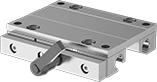
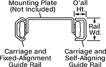
Self-Aligning Side-Mount Track Roller Carriages and Guide Rails
Create a self-aligning carriage and guide rail system to compensate for mounting surfaces that aren't parallel. The floating bearing in these carriages adjusts to correct misalignment between rails, so your carriages still move in tandem. A complete system includes a fixed-alignment carriage and rail on one side and a self-aligning carriage and rail on the other. All components are sold separately.
Carriages can be adjusted for a snug or loose fit on the rail (also known as preload). They have permanently lubricated rollers to save maintenance time and effort.
Fixed-alignment rails have a C-shaped profile that ensures the system travels in a straight line.
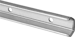
Self-aligning rails have a rectangular profile that allows the carriage to move freely from side to side to compensate for misalignment.
Zinc-Plated Steel Carriages with Adjustable Steel Rollers | ||||||||||||||
|---|---|---|---|---|---|---|---|---|---|---|---|---|---|---|
Misalignment Capability | Fixed-Alignment Zinc-Plated Steel Guide Rails | Self-Aligning Zinc-Plated Steel Guide Rails | ||||||||||||
| For Rail Wd., mm | Dynamic Load Cap., lbs. | O'all Ht., mm | Roller Dia., mm | Axial, mm | Parallel, mm | Max. Temp., °F | Each | Rail Lengths, mm | Per mm | Rail Lengths, mm | Per mm | |||
Fixed Alignment/Self Aligning | ||||||||||||||
| 39.5 | 350 | 28.65 | 31.5 | 1.6 | 3.4 | 245° | 1740N173 | 0000000 | 1740N27 | 00000 | 1740N81 | 00000 | ||
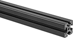
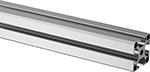
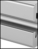
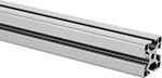
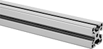
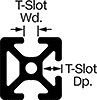
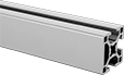
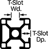
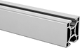
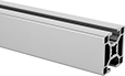
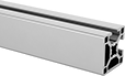
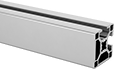
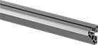
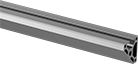
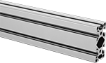
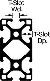
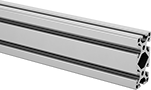
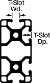
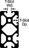
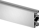
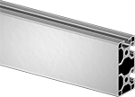
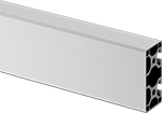
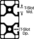
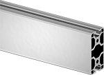
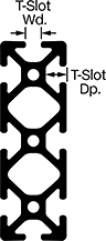
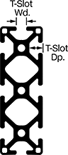
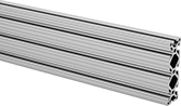
T-Slotted Framing Rails
Use this versatile framing to configure machine guards, enclosures, carts, and workstations. These rails have continuous T-slots for attaching fittings. When choosing how many slots you want on your rail, consider how much flexibility you need for your setup and how finished you'd like your structure to appear. The more slots the rail has, the more design flexibility you will have. Keep in mind, open slots can collect dust and debris. Rails with closed sides give you a finished appearance but are more difficult to reconfigure or add components to later. All of these rails are made of aluminum.
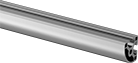
Radius, angled, and half-round rails give a finished appearance. They are often used to create finished edges or handles on carts.
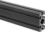
Double-, triple-, and quad-profile rails are good for large structural applications, such as beams and posts. Typically, the larger the rail profile, the stronger the rail.
Solid rails are stronger than hollow rails. Hollow rails are lighter and more economical than solid rails.
Smooth rails give a finished look. With no indentations to collect dust, they’re easier to clean than grooved rails. However, dents and marks are easier to see.
Black rails fade into the background and hide dirt and grime. They're good for vision systems where non-reflective material is needed. Yellow rails draw attention and are often used to build machine guards.
Cut-to-length rails can be ordered in increments of 0.125” or 0.25 cm.


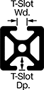
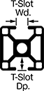
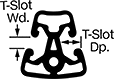
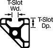
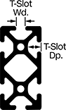
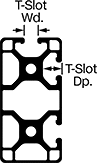
| Rail Ht. | Rail Wd. | Rail Construction | T-Slot Wd. | T-Slot Dp. | 1/2 ft. | 1 ft. | 1 1/2 ft. | 2 ft. | 3 ft. | 4 ft. | 5 ft. | 6 ft. | 8 ft. | 10 ft. | |
Silver Anodized Aluminum—Smooth Rail Texture | |||||||||||||||
|---|---|---|---|---|---|---|---|---|---|---|---|---|---|---|---|
| 40mm | 40mm | Hollow | 8mm | 12.2mm | 6575N25 | ||||||||||
| 40mm | 40mm | Solid | 8mm | 12.2mm | 5537T102 | ||||||||||
Black Anodized Aluminum—Smooth Rail Texture | |||||||||||||||
| 40mm | 40mm | Hollow | 8mm | 12.2mm | 4524N11 | ||||||||||
| 40mm | 40mm | Solid | 8mm | 12.2mm | 5537T507 | ||||||||||
Yellow Powder-Coated Aluminum—Smooth Rail Texture | |||||||||||||||
| 40mm | 40mm | Hollow | 8mm | 12.2mm | 4524N21 | ||||||||||
| 40mm | 40mm | Solid | 8mm | 12.2mm | 5537T508 | ||||||||||
To order: Please specify length in increments of 0.125” within the range listed.
Per Inch | ||||||||
|---|---|---|---|---|---|---|---|---|
| Rail Ht. | Rail Wd. | Rail Construction | T-Slot Wd. | T-Slot Dp. | Choose a Length | 1-23 | 24-Up | |
Silver Anodized Aluminum—Smooth Rail Texture | ||||||||
| 40mm | 40mm | Hollow | 8mm | 12.2mm | 2" to 240" in 0.125" increments | 6575N256 | 00000 | 00000 |
| 40mm | 40mm | Solid | 8mm | 12.2mm | 2" to 240" in 0.125" increments | 5537T913 | 0000 | 0000 |
Black Anodized Aluminum—Smooth Rail Texture | ||||||||
| 40mm | 40mm | Hollow | 8mm | 12.2mm | 0.75" to 240" in 0.125" increments | 6575N371 | 0000 | 0000 |
| 40mm | 40mm | Solid | 8mm | 12.2mm | 2" to 240" in 0.125" increments | 5537T928 | 0000 | 0000 |
Yellow Powder-Coated Aluminum—Smooth Rail Texture | ||||||||
| 40mm | 40mm | Solid | 8mm | 12.2mm | 2" to 144" in 0.125" increments | 5537T929 | 0000 | 0000 |
To order: Please specify length in increments of 0.25 cm within the range listed.
Per cm | ||||||||
|---|---|---|---|---|---|---|---|---|
| Rail Ht. | Rail Wd. | Rail Construction | T-Slot Wd. | T-Slot Dp. | Choose a Length | 1-59 | 60-Up | |
Silver Anodized Aluminum—Smooth Rail Texture | ||||||||
| 40mm | 40mm | Hollow | 8mm | 12.2mm | 2 cm to 609 cm in 0.25 cm increments | 6575N406 | 00000 | 00000 |
| 40mm | 40mm | Solid | 8mm | 12.2mm | 5 cm to 607 cm in 0.25 cm increments | 5537T904 | 000 | 000 |
Black Anodized Aluminum—Smooth Rail Texture | ||||||||
| 40mm | 40mm | Hollow | 8mm | 12.2mm | 2 cm to 609 cm in 0.25 cm increments | 6575N405 | 000 | 000 |
| 40mm | 40mm | Solid | 8mm | 12.2mm | 2 cm to 609 cm in 0.25 cm increments | 6575N407 | 000 | 000 |
To order: Please specify length in increments of 0.125” within the range listed.
Per Inch | ||||||||
|---|---|---|---|---|---|---|---|---|
| Rail Ht. | Rail Wd. | Rail Construction | T-Slot Wd. | T-Slot Dp. | Choose a Length | 1-23 | 24-Up | |
Silver Anodized Aluminum—Smooth Rail Texture | ||||||||
| 40mm | 40mm | Hollow | 8mm | 12.2mm | 0.75" to 240" in 0.125" increments | 6575N363 | 00000 | 00000 |
To order: Please specify length in increments of 0.125” within the range listed.


To order: Please specify length in increments of 0.125” within the range listed.


To order: Please specify length in increments of 0.125” within the range listed.
Per Inch | |||||||||
|---|---|---|---|---|---|---|---|---|---|
| Rail Ht. | Rail Wd. | Rail Construction | T-Slot Wd. | T-Slot Dp. | Angle | Choose a Length | 1-23 | 24-Up | |
Silver Anodized Aluminum—Smooth Rail Texture | |||||||||
| 40mm | 40mm | Hollow | 8mm | 12.2mm | 45° | 2" to 145" in 0.125" increments | 6575N259 | 00000 | 00000 |

To order: Please specify length in increments of 0.125” within the range listed.
Per Inch | ||||||||||
|---|---|---|---|---|---|---|---|---|---|---|
| Rail Ht. | Rail Wd. | Rail Construction | T-Slot Wd. | T-Slot Dp. | Angle | Radius | Choose a Length | 1-23 | 24-Up | |
Silver Anodized Aluminum—Smooth Rail Texture | ||||||||||
| 40mm | 40mm | Hollow | 8mm | 12.2mm | 30° | 40mm | 2" to 240" in 0.125" increments | 6575N257 | 00000 | 00000 |

To order: Please specify length in increments of 0.125” within the range listed.
Per Inch | |||||||||
|---|---|---|---|---|---|---|---|---|---|
| Rail Ht., mm | Rail Wd., mm | Rail Construction | T-Slot Wd., mm | T-Slot Dp., mm | Angle | Choose a Length | 1-23 | 24-Up | |
Silver Anodized Aluminum—Smooth Rail Texture | |||||||||
| 40 | 40 | Hollow | 8 | 12.2 | 45° | 2" to 145" in 0.125" increments | 6575N258 | 00000 | 00000 |
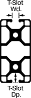
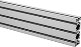
| Rail Ht. | Rail Wd. | Rail Construction | T-Slot Wd. | T-Slot Dp. | 1/2 ft. | 1 ft. | 1 1/2 ft. | 2 ft. | 3 ft. | 4 ft. | 5 ft. | 6 ft. | 8 ft. | 10 ft. | |
Silver Anodized Aluminum—Smooth Rail Texture | |||||||||||||||
|---|---|---|---|---|---|---|---|---|---|---|---|---|---|---|---|
| 80mm | 40mm | Hollow | 8mm | 12.2mm | 3136N73 | ||||||||||
| 80mm | 40mm | Solid | 8.1mm | 12.3mm | 5537T112 | ||||||||||
Black Anodized Aluminum—Smooth Rail Texture | |||||||||||||||
| 80mm | 40mm | Hollow | 8mm | 12.2mm | 4524N26 | ||||||||||
| 80mm | 40mm | Solid | 8.1mm | 12.3mm | 5537T587 | ||||||||||

To order: Please specify length in increments of 0.125” within the range listed.
Per Inch | ||||||||
|---|---|---|---|---|---|---|---|---|
| Rail Ht. | Rail Wd. | Rail Construction | T-Slot Wd. | T-Slot Dp. | Choose a Length | 1-23 | 24-Up | |
Silver Anodized Aluminum—Smooth Rail Texture | ||||||||
| 80mm | 40mm | Hollow | 8mm | 12.2mm | 0.75" to 240" in 0.125" increments | 6575N393 | 00000 | 00000 |
| 80mm | 40mm | Solid | 8mm | 12.2mm | 2" to 240" in 0.125" increments | 5537T914 | 0000 | 0000 |
Black Anodized Aluminum—Smooth Rail Texture | ||||||||
| 80mm | 40mm | Hollow | 8mm | 12.2mm | 2" to 240" in 0.125" increments | 6575N262 | 0000 | 0000 |
| 80mm | 40mm | Solid | 8mm | 12.2mm | 2" to 240" in 0.125" increments | 6575N261 | 0000 | 0000 |
To order: Please specify length in increments of 0.25 cm within the range listed.

To order: Please specify length in increments of 0.125” within the range listed.
Per Inch | ||||||||
|---|---|---|---|---|---|---|---|---|
| Rail Ht. | Rail Wd. | Rail Construction | T-Slot Wd. | T-Slot Dp. | Choose a Length | 1-23 | 24-Up | |
Silver Anodized Aluminum—Smooth Rail Texture | ||||||||
| 80mm | 40mm | Hollow | 8mm | 12.2mm | 2" to 240" in 0.125" increments | 6575N266 | 00000 | 00000 |

To order: Please specify length in increments of 0.125” within the range listed.
Per Inch | ||||||||
|---|---|---|---|---|---|---|---|---|
| Rail Ht. | Rail Wd. | Rail Construction | T-Slot Wd. | T-Slot Dp. | Choose a Length | 1-23 | 24-Up | |
Silver Anodized Aluminum—Smooth Rail Texture | ||||||||
| 80mm | 40mm | Hollow | 8mm | 12.2mm | 2" to 240" in 0.125" increments | 6575N265 | 00000 | 00000 |

To order: Please specify length in increments of 0.125” within the range listed.
Per Inch | ||||||||
|---|---|---|---|---|---|---|---|---|
| Rail Ht. | Rail Wd. | Rail Construction | T-Slot Wd. | T-Slot Dp. | Choose a Length | 1-23 | 24-Up | |
Silver Anodized Aluminum—Smooth Rail Texture | ||||||||
| 80mm | 40mm | Hollow | 8mm | 12.2mm | 2" to 240" in 0.125" increments | 6575N264 | 00000 | 00000 |

To order: Please specify length in increments of 0.125” within the range listed.
Per Inch | ||||||||
|---|---|---|---|---|---|---|---|---|
| Rail Ht. | Rail Wd. | Rail Construction | T-Slot Wd. | T-Slot Dp. | Choose a Length | 1-23 | 24-Up | |
Silver Anodized Aluminum—Smooth Rail Texture | ||||||||
| 80mm | 40mm | Hollow | 8mm | 12.2mm | 2" to 240" in 0.125" increments | 6575N263 | 00000 | 00000 |
To order: Please specify length in increments of 0.125” within the range listed.
Per Inch | ||||||||
|---|---|---|---|---|---|---|---|---|
| Rail Ht. | Rail Wd. | Rail Construction | T-Slot Wd. | T-Slot Dp. | Choose a Length | 1-23 | 24-Up | |
Silver Anodized Aluminum—Smooth Rail Texture | ||||||||
| 120mm | 40mm | Solid | 8mm | 12.2mm | 0.75" to 240" in 0.125" increments | 6575N376 | 00000 | 00000 |
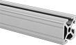
Lightweight Composite T-Slotted Framing and Fittings
Build lightweight structures, such as light duty machine guards, enclosures, and carts, with framing that is two-thirds the weight of aluminum framing. Made of 30% polypropylene and 70% wood, they’re not as strong as aluminum rails, but they’re nonconductive, easy to machine, and more corrosion resistant. Good for lab environments, they also withstand cleaning with chemicals better than aluminum. Use their continuous T-slots to attach fittings. They work with any T-slotted component for 40 mm rails that doesn’t require machining. View additional structural brackets and fasteners.
Double rails are stronger than single rails.