



























Filter by
Maximum Temperature
Material

Export Control Classification Number (ECCN)

DFARS Specialty Metals
Performance
Sleeving Type

Sleeving Construction


Certification
Military Specification
Minimum Temperature
Component
Maximum Pull @ Distance
Electrical Discharge Machining Electrode Guides
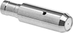 |
These ceramic guides hold tube electrodes in place as they penetrate the workpiece. By reducing deflection and wander, they improve hole accuracy and consistency. Ceramic construction resists electrical conductivity and withstands the heat generated during machining.
Also known as spark machining, electrical discharge machining (EDM) uses electrical current to erode a metal workpiece to a desired shape.
Coordinate Measurement Machine Probes for CNC Machines
Probes
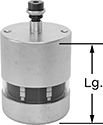 |
Infrared—Infrared probes send data to a receiver up to 5 meters away, but because they use light, they need a clear view.
Radio— Radio probes send data to a receiver up to 15 meters away. They block out interference from other radio devices, so you can use multiple radio probes in one machine shop.
40 mm Diameter—40 mm probes are typically found in small and medium machines with a chuck size between 6" and 15".
63 mm Diameter—63 mm probes are typically found in medium to large machines with a chuck size between 10" and 24".
Coordinate Measurement Machine Probes | Replacement Batteries | ||||||||||||||||
|---|---|---|---|---|---|---|---|---|---|---|---|---|---|---|---|---|---|
For Stylus | Trigger Force, N | ||||||||||||||||
Dia., mm | Lg., mm | Thread Size | O'all Lg., mm | For Axis Measuring Direction | X- and Y-Axis | Z-Axis | Repeatability, mm | Max. Distance from Receiver, m | Enclosure Rating | Manufacturer (Series) | Each | Pkg. Qty. | Pkg. | ||||
Infrared | |||||||||||||||||
| 40 | 50 | M4 | 50 to 150 | ±X, ±Y, +Z | 0.5, 0.9 | 5.85 | -0.001 to 0.001 | 5 | IK01, IP08 | Renishaw (OMP40) | 6206N11 | 000000000 | 1 | 6951K59 | 00000 | ||
| 63 | 76 | M4 | 50 to 150 | ±X, ±Y, +Z | 0.75, 1.4 | 5.3 | -0.001 to 0.001 | 6 | IP08 | Renishaw (OMP60) | 6206N12 | 00000000 | 1 | 6951K57 | 0000 | ||
Radio | |||||||||||||||||
| 40 | 50 | M4 | 50 to 150 | ±X, ±Y, +Z | 0.5, 0.9 | 5.85 | -0.001 to 0.001 | 15 | IK01, IP08 | Renishaw (RMP40-QE) | 6206N17 | 00000000 | 1 | 6951K59 | 0000 | ||
| 63 | 76 | M4 | 50 to 150 | ±X, ±Y, +Z | 0.75, 1.4 | 5.3 | -0.001 to 0.001 | 15 | IP08 | Renishaw (RMP60-QE) | 6206N18 | 00000000 | 1 | 6951K57 | 0000 | ||
 |
Receiver |
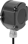
For Infrared Probes—Infrared probes send data to a receiver up to 5 meters away, but because they use light, they need a clear view.
Component | For Max. No. of Probes | Wire Connection | Cord Lg., ft. | Manufacturer (Series) | Each | |||
|---|---|---|---|---|---|---|---|---|
For Infrared Probes | ||||||||
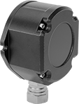
| Receiver | 4 | Wire Leads | 82 | Renishaw (OMM-2) | 6206N13 | 000000000 | ||
 |
Interface |
Component | Wire Connection | Manufacturer (Series) | Each | |||
|---|---|---|---|---|---|---|
For Infrared Probes | ||||||
| Interface | Screw Terminal | Renishaw (OSI) | 6206N14 | 000000000 | ||
 |
Receiver/Interface |
For Infrared Probes—Infrared probes send data to a receiver up to 5 meters away, but because they use light, they need a clear view.
For Radio Probes— Radio probes send data to a receiver up to 15 meters away. They block out interference from other radio devices, so you can use multiple radio probes in one machine shop.
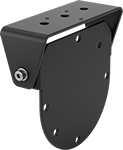 |
Receiver mounting brackets make it easy to attach a receiver or receiver/interface to your machine.
Color | Material | Mounting Fasteners Included | Mfr. | Mfr. Model No. | Each | ||
|---|---|---|---|---|---|---|---|
| Black | Powder-Coated Steel | Yes | Renishaw | A-2033-0830 | 6206N21 | 0000000 |
 |
For Probe Dia., mm | Shank Type | For Probe Mfr. Series | Mfr. | Mfr. Model No. | Each | ||
|---|---|---|---|---|---|---|---|
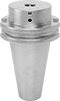
| 40 | BT 40 Taper | OMP40, RMP40-QE | Renishaw | M-4071-0057 | 6206N26 | 0000000 | |
| 40 | BT 50 Taper | OMP40, RMP40-QE | Renishaw | M-4071-0071 | 6206N27 | 000000 | |
| 40 | CAT 40 Taper | OMP40, RMP40-QE | Renishaw | M-4071-0058 | 6206N22 | 000000 | |
| 40 | CAT 50 Taper | OMP40, RMP40-QE | Renishaw | M-4071-0072 | 6206N23 | 000000 | |
| 63 | BT 40 Taper | OMP60, RMP60-QE | Renishaw | M-2045-0027 | 6206N28 | 000000 | |
| 63 | BT 50 Taper | OMP60, RMP60-QE | Renishaw | M-2045-0073 | 6206N29 | 000000 | |
| 63 | CAT 40 Taper | OMP60, RMP60-QE | Renishaw | M-2045-0069 | 6206N24 | 000000 | |
| 63 | CAT 50 Taper | OMP60, RMP60-QE | Renishaw | M-2045-0071 | 6206N25 | 000000 |
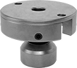 |
Add a shank adapter to fit 40 mm probes to shanks made for 63 mm probes.
For Probe Manufacturer Series | Compatible with Shanks for Probe Manufacturer Series | Mfr. | Mfr. Model No. | Each | ||
|---|---|---|---|---|---|---|
| OMP40, RMP40-QE | MP11, MP12, MP700, MP700E, OMP60, RMP60-QE | Renishaw | A-4071-0031 | 6206N16 | 0000000 |
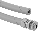 |
Conduit Trade Size | Cord Lg., ft. | Mfr. | Mfr. Model No. | Each | ||
|---|---|---|---|---|---|---|
| 5/16 | 3 | Renishaw | A-4113-0306 | 6206N15 | 000000 |
Magnetic Conveyor Belt Plates
Conveyor Plates—Ferrite Ceramic with Stainless Steel Casing
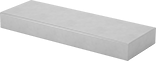 |  |
Plate | Plate with Stainless Steel Bracket |
 |  |
Full Magnetic Coverage | Partial Magnetic Coverage |
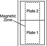
Full Magnetic Coverage—Conveyor plates with full magnetic coverage have a higher magnetic force than conveyor plates with partial magnetic coverage. They have a full magnetic zone throughout the plate, making them best for moving large objects. Position them side-by-side or end-to-end to cover the entire width or length of the belt. All have tapped holes for mounting.
Partial Magnetic Coverage—Conveyor plates with partial magnetic coverage have a magnetic zone that runs down the center of the plate's length. They’re typically placed underneath the middle of the belt to pull small objects that are prone to shifting due to vibration, such as lids and fasteners, towards the center of the belt for secure conveying. If used with large objects, only a part of the object will be secured. When installing multiple plates down your conveyor run, be sure the poles are opposite of each other. All have mounting brackets for quick installation.
12" Long | 24" Long | 36" Long | 48" Long | 60" Long | |||||||||||
|---|---|---|---|---|---|---|---|---|---|---|---|---|---|---|---|
Wd. | Thk. | Max. Pull @ Distance | Bracket Material | Each | Each | Each | Each | Each | |||||||
Full Magnetic Coverage | |||||||||||||||
| 4 1/8" | 1 5/16" | 7 1/2 lbf @ 1/8" | — | 6497N111 | 0000000 | 6497N112 | 000000000 | 6497N113 | 000000000 | 6497N114 | 000000000 | 6497N115 | 000000000 | ||
| 4 1/8" | 2 5/16" | 9 1/2 lbf @ 1/8" | — | 6497N131 | 000000 | 6497N132 | 00000000 | 6497N133 | 00000000 | 6497N134 | 00000000 | 6497N135 | 00000000 | ||
Partial Magnetic Coverage | |||||||||||||||
| 1 5/8" | 1 5/32" | 2 1/2 lbf @ 1/8" | Stainless Steel | 6497N151 | 000000 | 6497N152 | 000000 | 6497N153 | 00000000 | 6497N154 | 00000000 | 6497N155 | 00000000 | ||
| 3" | 1 5/32" | 5 lbf @ 1/8" | Stainless Steel | 6497N171 | 000000 | 6497N172 | 000000 | 6497N173 | 00000000 | 6497N174 | 00000000 | 6497N175 | 00000000 | ||
| 3 5/8" | 1 29/32" | 5 3/4 lbf @ 1/8" | Stainless Steel | 6497N191 | 000000 | 6497N192 | 00000000 | 6497N193 | 00000000 | 6497N194 | 00000000 | 6497N195 | 00000000 | ||
Transfer Plates—Ferrite Ceramic with Stainless Steel Casing
 |  |  |
Straight End | Straight End Stainless Steel Bracket | Tapered End Stainless Steel Bracket |
| |
Full Magnetic Coverage | Partial Magnetic Coverage |
12" Long | |||||||
|---|---|---|---|---|---|---|---|
Wd. | Thk. | Max. Pull @ Distance | Bracket Material | Each | |||
Full Magnetic Coverage—Straight End | |||||||
| 4 1/8" | 1 5/16" | 7 1/2 lbf @ 1/8" | — | 6497N201 | 0000000 | ||
| 4 1/8" | 2 5/16" | 9 1/2 lbf @ 1/8" | — | 6497N202 | 000000 | ||
Partial Magnetic Coverage—Straight End | |||||||
| 1 5/8" | 1 5/32" | 2 1/2 lbf @ 1/8" | Stainless Steel | 6497N221 | 000000 | ||
| 3" | 1 5/32" | 5 lbf @ 1/8" | Stainless Steel | 6497N222 | 000000 | ||
| 3 5/8" | 1 29/32" | 5 3/4 lbf @ 1/8" | Stainless Steel | 6497N223 | 000000 | ||
Partial Magnetic Coverage—Tapered End | |||||||
| 1 5/8" | 1 5/32" | 2 1/2 lbf @ 1/8" | Stainless Steel | 6497N241 | 000000 | ||
| 3" | 1 5/32" | 5 lbf @ 1/8" | Stainless Steel | 6497N242 | 000000 | ||
| 3 5/8" | 1 29/32" | 5 3/4 lbf @ 1/8" | Stainless Steel | 6497N243 | 000000 | ||
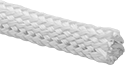
No-Irritation Ceramic High-Temperature Wire Sleeving
Ceramic Fabric
 |
ID | Wall Thk. | Max. Temp., ° F | Mil. Spec. | Color | 1 ft. Long | 3 ft. Long | 5 ft. Long | 10 ft. Long | 25 ft. Long | 100 ft. Long | ||
|---|---|---|---|---|---|---|---|---|---|---|---|---|
| 1/16" | 1/32" | 2,600 | MIL-I-24244 | White | 87675K1 | 000000 | 000000 | 000000 | 0000000 | — | — | |
| 1/8" | 1/32" | 2,600 | MIL-I-24244 | White | 87675K2 | 00000 | 00000 | 00000 | 000000 | — | — | |
| 1/8" | 1/16" | 1,100 | MIL-I-24244 | White | 88175K31 | — | 0000 | — | 00000 | 000000 | 0000000 | |
| 1/4" | 1/32" | 2,600 | MIL-I-24244 | White | 87675K3 | 00000 | 00000 | 000000 | 000000 | — | — | |
| 1/4" | 1/16" | 1,100 | MIL-I-24244 | White | 88175K32 | — | 0000 | — | 00000 | 00000 | 000000 | |
| 3/8" | 1/16" | 1,100 | MIL-I-24244 | White | 88175K33 | — | 0000 | — | 00000 | 00000 | 000000 | |
| 1/2" | 1/32" | 2,600 | MIL-I-24244 | White | 87675K4 | 00000 | 000000 | 000000 | 000000 | — | — | |
| 1/2" | 1/16" | 1,100 | MIL-I-24244 | White | 88175K34 | — | 0000 | — | 00000 | 00000 | 000000 | |
| 3/4" | 1/16" | 1,100 | MIL-I-24244 | White | 88175K35 | — | 00000 | — | 00000 | 00000 | 000000 | |
| 1" | 1/32" | 2,600 | MIL-I-24244 | White | 87675K5 | 000000 | 000000 | 000000 | 000000 | — | — | |
| 1" | 1/16" | 1,100 | MIL-I-24244 | White | 88175K36 | — | 00000 | — | 00000 | 00000 | 000000 | |
| 1 1/2" | 1/16" | 1,100 | MIL-I-24244 | White | 88175K37 | — | 00000 | — | 00000 | 000000 | 000000 | |
| 2" | 1/16" | 1,100 | MIL-I-24244 | White | 88175K38 | — | 00000 | — | 00000 | 000000 | 000000 |
Coordinate Measurement Machine Probes for CNC Lathes
Probes
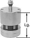 |
Coordinate Measurement Machine Probes | Replacement Batteries | ||||||||||||||||
|---|---|---|---|---|---|---|---|---|---|---|---|---|---|---|---|---|---|
For Stylus | Trigger Force, N | ||||||||||||||||
Dia., mm | Lg., mm | Thread Size | O'all Lg., mm | For Axis Measuring Direction | X- and Y-Axis | Z-Axis | Repeatability, mm | Max. Distance from Receiver, m | Enclosure Rating | Manufacturer (Series) | Each | Pkg. Qty. | Pkg. | ||||
Infrared | |||||||||||||||||
| 40 | 58 | M4 | 50 to 150 | ±X, ±Y, +Z | 0.4, 0.8 | 5.3 | -0.001 to 0.001 | 5 | IK02, IP08 | Renishaw (OLP40) | 6192N11 | 000000000 | 1 | 6951K59 | 00000 | ||
Radio | |||||||||||||||||
| 40 | 58 | M4 | 50 to 150 | ±X, ±Y, +Z | 0.6, 0.97 | 6.23 | -0.001 to 0.001 | 15 | IK02, IP08 | Renishaw (RLP40-QE) | 6192N12 | 00000000 | 1 | 6951K59 | 0000 | ||
|
Receiver |
For Infrared Probes—Infrared probes send data to a receiver up to 5 meters away, but because they use light, they need a clear view. These probes are typically found in small lathes with chuck sizes around 8” and medium lathes with chuck sizes around 15”. They can also be used on a 5-axis CNC with a table size under 1,500 mm.
Component | For Max. No. of Probes | Wire Connection | Cord Lg., ft. | Manufacturer (Series) | Each | |||
|---|---|---|---|---|---|---|---|---|
For Infrared Probes | ||||||||
| Receiver | 4 | Wire Leads | 82 | Renishaw (OMM-2) | 6206N13 | 000000000 | ||
|
Interface |
Component | Wire Connection | Manufacturer (Series) | Each | |||
|---|---|---|---|---|---|---|
For Infrared Probes | ||||||
| Interface | Screw Terminal | Renishaw (OSI) | 6206N14 | 000000000 | ||
|
Receiver/Interface |
For Infrared Probes—Infrared probes send data to a receiver up to 5 meters away, but because they use light, they need a clear view. These probes are typically found in small lathes with chuck sizes around 8” and medium lathes with chuck sizes around 15”. They can also be used on a 5-axis CNC with a table size under 1,500 mm.
For Radio Probes—Radio probes send data to a receiver up to 15 meters away. They block out interference from other radio devices, so you can use multiple radio probes in one machine shop. They’re used in small, medium, and large lathes with a chuck size up to 24". They can also be used on a 5-axis CNC with a table size under 3,500 mm.
|
Receiver mounting brackets make it easy to attach a receiver or receiver/interface to your lathe.
Color | Material | Mounting Fasteners Included | Mfr. | Mfr. Model No. | Each | ||
|---|---|---|---|---|---|---|---|
| Black | Powder-Coated Steel | Yes | Renishaw | A-2033-0830 | 6206N21 | 0000000 |
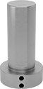 |
Use a shank to attach a probe to the spindle on your CNC lathe.
|
Conduit Trade Size | Cord Lg., ft. | Mfr. | Mfr. Model No. | Each | ||
|---|---|---|---|---|---|---|
| 5/16 | 3 | Renishaw | A-4113-0306 | 6206N15 | 000000 |
Modular Coordinate Measurement Machine Probes
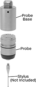 |
Probe Base and Probe Sold Separately |
Swap out Renishaw probe styles to inspect different features on a part without having to recalibrate. These probes mount magnetically to a base that threads into your coordinate measuring machine (CMM), making mid-inspection changes quick. They’re also known as modules. It’s easy to tell different styles apart from their different end colors. To take 3D measurements, they record the coordinates of different points on your workpiece. Because this involves physically touching your workpiece, they’re more accurate than other automated measurement systems. They’re touch-trigger probes, the most common CMM probe type, which means they stop to record the coordinates of one point at a time. Use them to check distances, diameters, right angles, and the location of holes and grooves. However, they're not as good at checking complex features, flatness, or roundness.
All probes require a stylus as well as a base (sold separately for some probes).
Trigger force is the amount of force required for a probe to take a measurement and record it. Choose a probe with a force that is high enough to avoid false triggers from vibration but not so high it damages the workpiece and leads to inaccurate measurements.
Probes
 |
6W Series—6W series probes work well if you need to inspect features on the bottom of a part, such as overhangs and undercuts. They measure in six directions instead of five.
MF Series—MF series probes have a slightly higher trigger force than typical applications require to account for vibration.
EF Series—EF series probes have the highest trigger force, so they’re the best choice for environments with vibration. They also work well for larger styli, such as long 5-star styli.
For Stylus | Trigger Force, N | ||||||||||
|---|---|---|---|---|---|---|---|---|---|---|---|
Dia., mm | Lg., mm | Thread Size | O'all Lg., mm | For Axis Measuring Direction | X- and Y-Axis | Z-Axis | End Color | Each | |||
Renishaw (6W) | |||||||||||
| 13 | 24 | M2 | 10 to 30 | ±X, ±Y, ±Z | 0.14 | 1.6 | Blue | 6179N18 | 000000000 | ||
Renishaw (MF) | |||||||||||
| 13 | 20 | M2 | 10 to 60 | ±X, ±Y, +Z | 0.1 | 1.9 | Gray | 6179N15 | 00000000 | ||
Renishaw (EF) | |||||||||||
| 13 | 20 | M2 | 10 to 60 | ±X, ±Y, +Z | 0.1 | 3.2 | Brown | 6179N16 | 00000000 | ||
 |
For Probe Mfr. Series | Mfr. | Mfr. Model No. | Each | ||
|---|---|---|---|---|---|
| TP20, TP20 NI | Renishaw | A-1042-1486 | 6179N23 | 000000 |
