


Filter by
For Use With
Maximum Pressure
Maximum Flow Rate
Fixed Displacement Rate
Flow Rate

Overall Length

Drive Direction


Capacity
Thread Type
Export Control Classification Number (ECCN)
DFARS Specialty Metals
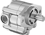
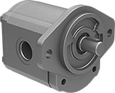
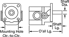
Hydraulic Gear Pumps
SAE AA—3 1/4" Mounting Hole Center-to-Center
 |  |
UN/UNF (SAE Straight) Thread—UN/UNF (SAE Straight) thread connections have straight threads and are also known as O-ring Boss fittings.
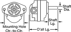
Inlet Connection | Outlet Connection | Overall | Shaft | |||||||||||||||
|---|---|---|---|---|---|---|---|---|---|---|---|---|---|---|---|---|---|---|
Fixed Displacement Rate, in³/rev | Max. Flow Rate | Max. Pressure, psi | Max. Rotation Speed, rpm | Thread Size | Thread Type | Dash Size | Thread Size | Thread Type | Dash Size | Lg. | Ht. | Dia. | Lg. | Choose a Drive Direction | Each | |||
| 0.11 | 1.7 gpm | 2,500 | 4,000 | 7/8"-14 | UN/UNF (SAE Straight) | 10 | 3/4"-16 | UN/UNF (SAE Straight) | 08 | 4" | 3 5/8" | 1/2" | 1 1/4" | Clockwise, Counterclockwise | 6296K44 | 0000000 | ||
| 0.21 | 3.3 gpm | 2,500 | 4,000 | 7/8"-14 | UN/UNF (SAE Straight) | 10 | 3/4"-16 | UN/UNF (SAE Straight) | 08 | 4 1/4" | 3 5/8" | 1/2" | 1 1/4" | Clockwise, Counterclockwise | 6296K45 | 000000 | ||
| 0.33 | 5.2 gpm | 2,500 | 4,000 | 7/8"-14 | UN/UNF (SAE Straight) | 10 | 3/4"-16 | UN/UNF (SAE Straight) | 08 | 4 3/8" | 3 5/8" | 1/2" | 1 1/4" | Clockwise, Counterclockwise | 6296K47 | 000000 | ||
| 0.52 | 8.4 gpm | 2,500 | 4,000 | 7/8"-14 | UN/UNF (SAE Straight) | 10 | 3/4"-16 | UN/UNF (SAE Straight) | 08 | 4 3/4" | 3 5/8" | 1/2" | 1 1/4" | Clockwise, Counterclockwise | 6296K53 | 000000 | ||
| 0.64 | 7.8 gpm | 2,000 | 3,000 | 7/8"-14 | UN/UNF (SAE Straight) | 10 | 3/4"-16 | UN/UNF (SAE Straight) | 08 | 4 7/8" | 3 5/8" | 1/2" | 1 1/4" | Clockwise, Counterclockwise | 6296K55 | 000000 | ||
SAE A—4 3/16" Mounting Hole Center-to-Center
 | |
UN/UNF (SAE Straight) Thread—UN/UNF (SAE Straight) thread connections have straight threads and are also known as O-ring Boss fittings.
Inlet Connection | Outlet Connection | Overall | Shaft | |||||||||||||||
|---|---|---|---|---|---|---|---|---|---|---|---|---|---|---|---|---|---|---|
Fixed Displacement Rate, in³/rev | Max. Flow Rate | Max. Pressure, psi | Max. Rotation Speed, rpm | Thread Size | Thread Type | Dash Size | Thread Size | Thread Type | Dash Size | Lg. | Ht. | Dia. | Lg. | Choose a Drive Direction | Each | |||
| 0.37 | 5.9 gpm | 4,000 | 4,000 | 7/8"-14 | UN/UNF (SAE Straight) | 10 | 3/4"-16 | UN/UNF (SAE Straight) | 08 | 4 7/8" | 4 5/8" | 3/4" | 1" | Clockwise, Counterclockwise | 6296K25 | 0000000 | ||
| 0.49 | 7.9 gpm | 4,000 | 4,000 | 1 1/16"-12 | UN/UNF (SAE Straight) | 12 | 7/8"-14 | UN/UNF (SAE Straight) | 10 | 5" | 4 5/8" | 3/4" | 1" | Clockwise, Counterclockwise | 6296K26 | 000000 | ||
| 0.61 | 9.9 gpm | 4,000 | 4,000 | 1 1/16"-12 | UN/UNF (SAE Straight) | 12 | 7/8"-14 | UN/UNF (SAE Straight) | 10 | 5 1/8" | 4 5/8" | 3/4" | 1" | Clockwise, Counterclockwise | 6296K27 | 000000 | ||
| 0.98 | 11.9 gpm | 4,000 | 3,000 | 1 1/16"-12 | UN/UNF (SAE Straight) | 12 | 7/8"-14 | UN/UNF (SAE Straight) | 10 | 5 1/2" | 4 5/8" | 3/4" | 1" | Clockwise, Counterclockwise | 6296K28 | 000000 | ||
| 1.16 | 14.1 gpm | 4,000 | 3,000 | 1 5/16"-12 | UN/UNF (SAE Straight) | 16 | 1 1/16"-12 | UN/UNF (SAE Straight) | 12 | 5 5/8" | 4 5/8" | 3/4" | 1" | Clockwise, Counterclockwise | 6296K29 | 000000 | ||
| 1.4 | 15.9 gpm | 3,200 | 2,800 | 1 5/16"-12 | UN/UNF (SAE Straight) | 16 | 1 1/16"-12 | UN/UNF (SAE Straight) | 12 | 5 7/8" | 4 5/8" | 3/4" | 1" | Clockwise, Counterclockwise | 6296K37 | 000000 | ||
| 1.65 | 16.1 gpm | 2,700 | 2,400 | 1 5/16"-12 | UN/UNF (SAE Straight) | 16 | 1 1/16"-12 | UN/UNF (SAE Straight) | 12 | 6 1/8" | 4 5/8" | 3/4" | 1" | Clockwise, Counterclockwise | 6296K38 | 000000 | ||
SAE B—5 3/4" Mounting Hole Center-to-Center
 | |
UN/UNF (SAE Straight) Thread—UN/UNF (SAE Straight) thread connections have straight threads and are also known as O-ring Boss fittings.
Inlet Connection | Outlet Connection | Overall | Shaft | |||||||||||||||
|---|---|---|---|---|---|---|---|---|---|---|---|---|---|---|---|---|---|---|
Fixed Displacement Rate, in³/rev | Max. Flow Rate | Max. Pressure, psi | Max. Rotation Speed, rpm | Thread Size | Thread Type | Dash Size | Thread Size | Thread Type | Dash Size | Lg. | Ht. | Dia. | Lg. | Choose a Drive Direction | Each | |||
| 2.01 | 24.5 gpm | 4,000 | 3,000 | 1 5/8"-12 | UN/UNF (SAE Straight) | 20 | 1 5/16"-12 | UN/UNF (SAE Straight) | 16 | 7 1/8" | 5 7/8" | 7/8" | 1 1/4" | Clockwise, Counterclockwise | 6296K39 | 0000000 | ||
| 2.32 | 28.3 gpm | 4,000 | 3,000 | 1 5/8"-12 | UN/UNF (SAE Straight) | 20 | 1 5/16"-12 | UN/UNF (SAE Straight) | 16 | 7 3/8" | 5 7/8" | 7/8" | 1 1/4" | Clockwise | 6296K73 | 000000 | ||
| 3.05 | 33.5 gpm | 2,900 | 2,700 | 1 5/8"-12 | UN/UNF (SAE Straight) | 20 | 1 5/16"-12 | UN/UNF (SAE Straight) | 16 | 7 3/4" | 5 7/8" | 7/8" | 1 1/4" | Clockwise, Counterclockwise | 6296K59 | 000000 | ||
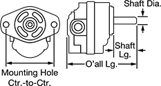
SAE 4F17—2" Mounting Hole Center-to-Center
 |  |
Inlet Connection | Outlet Connection | Overall | Shaft | |||||||||||||||
|---|---|---|---|---|---|---|---|---|---|---|---|---|---|---|---|---|---|---|
Fixed Displacement Rate, in³/rev | Max. Flow Rate | Max. Pressure, psi | Max. Rotation Speed, rpm | Thread Size | Thread Type | Dash Size | Thread Size | Thread Type | Dash Size | Lg. | Ht. | Dia. | Lg. | Drive Direction | Each | |||
| 0.07 | 0.8 gpm | 3,000 | 4,000 | 9/16"-18 | UN/UNF (SAE Straight) | 06 | 9/16"-18 | UN/UNF (SAE Straight) | 06 | 4 5/8" | 3 7/16" | 1/2" | 1 3/8" | Clockwise, Counterclockwise | 6296K51 | 0000000 | ||
| 0.13 | 1.7 gpm | 3,000 | 4,000 | 3/4"-16 | UN/UNF (SAE Straight) | 08 | 3/4"-16 | UN/UNF (SAE Straight) | 08 | 4 5/8" | 3 7/16" | 1/2" | 1 3/8" | Clockwise, Counterclockwise | 6296K71 | 000000 | ||
| 0.39 | 5 gpm | 3,000 | 4,000 | 7/8"-14 | UN/UNF (SAE Straight) | 10 | 7/8"-14 | UN/UNF (SAE Straight) | 10 | 5 1/8" | 3 7/16" | 1/2" | 1 3/8" | Clockwise, Counterclockwise | 6296K54 | 000000 | ||
| 0.71 | 5.4 gpm | 1,800 | 2,400 | 7/8"-14 | UN/UNF (SAE Straight) | 10 | 7/8"-14 | UN/UNF (SAE Straight) | 10 | 5 5/8" | 3 7/16" | 1/2" | 1 3/8" | Clockwise, Counterclockwise | 6296K56 | 000000 | ||
Hydraulic Power Units
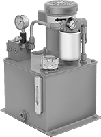 |
Create and supply hydraulic pressure. Choose a unit with a tank capacity about three times greater than your requirement to allow for heat dissipation. An inlet filter protects the pump from contamination.
All units include an additional NPTF threaded inlet port. NPTF (Dryseal) threads are compatible with NPT threads. UN/UNF (SAE Straight) thread connections have straight threads and are also known as O-ring Boss fittings.
Overall | Inlet Connection — UN/UNF (SAE Straight) | Inlet Connection — NPTF | Outlet Connection — UN/UNF (SAE Straight) | ||||||||||||||
|---|---|---|---|---|---|---|---|---|---|---|---|---|---|---|---|---|---|
Max. Flow Rate, gpm | Max. Pressure, psi | Power, hp | Cap., gal. | Lg. | Wd. | Ht. | Thread Size | Dash Size | Pipe Size | Dash Size | Thread Size | Dash Size | Full Load Current @ Voltage | Each | |||
240V AC/460V AC, Three Phase | |||||||||||||||||
| 0.9 | 1,600 | 1 | 5 | 13" | 15" | 20 1/2" | 7/8"-14 | 10 | 1/2 | 08 | 7/8"-14 | 10 | 1.5 amp @ 460V AC | 62915K31 | 000000000 | ||
| 1.3 | 2,300 | 2 | 5 | 13" | 15" | 24 1/2" | 7/8"-14 | 10 | 1/2 | 08 | 7/8"-14 | 10 | 2.8 amp @ 460V AC | 62915K32 | 00000000 | ||
| 2.7 | 1,750 | 3 | 10 | 17 3/8" | 19" | 32 1/2" | 1 1/16"-12 | 12 | 3/4 | 12 | 1 1/16"-12 | 12 | 4.4 amp @ 460V AC | 62915K33 | 00000000 | ||
| 3.6 | 2,050 | 5 | 10 | 17 3/4" | 19" | 29 3/4" | 1 1/16"-12 | 12 | 3/4 | 12 | 1 1/16"-12 | 12 | 6.8 amp @ 460V AC | 62915K44 | 00000000 | ||
| 6.3 | 1,800 | 7 1/2 | 20 | 21 3/8" | 22 1/2" | 37 3/8" | 1 1/16"-12 | 12 | 3/4 | 12 | 1 1/16"-12 | 12 | 9.5 amp @ 460V AC | 62915K36 | 00000000 | ||
| 8.6 | 1,700 | 10 | 30 | 21 3/8" | 22 1/2" | 42 1/4" | 1 1/16"-12 | 12 | 3/4 | 12 | 1 1/16"-12 | 12 | 12 amp @ 460V AC | 62915K47 | 00000000 | ||
| 10.4 | 2,100 | 15 | 30 | 23 3/8" | 22 1/2" | 44 1/8" | 1 1/16"-12 | 12 | 3/4 | 12 | 1 1/16"-12 | 12 | 18.1 amp @ 460V AC | 62915K48 | 000000000 | ||
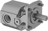
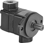
Smooth-Operating Hydraulic Rotary Vane Pumps
 |  |
Inlet Connection—NPT | Outlet Connection—NPT | Overall | Shaft | |||||||||||||||
|---|---|---|---|---|---|---|---|---|---|---|---|---|---|---|---|---|---|---|
SAE Pump Flange Size | Fixed Displacement Rate, in³/rev | Max. Flow Rate, gpm | Max. Pressure, psi | Max. Rotation Speed, rpm | Pipe Size | Dash Size | Pipe Size | Dash Size | Lg. | Ht. | Dia. | Lg. | Mounting Hole Ctr.-to-Ctr. | Drive Direction | Each | |||
Opposite-Side Port | ||||||||||||||||||
| A | 0.6 | 4.6 | 1,500 | 1,800 | 1 | 16 | 1/2 | 08 | 6 5/16" | 4 13/16" | 3/4" | 1 7/16" | 4 3/16" | Clockwise | 1655N11 | 000000000 | ||
| A | 1.19 | 9.2 | 1,500 | 1,800 | 1 | 16 | 1/2 | 08 | 6 3/4" | 4 13/16" | 3/4" | 1 7/16" | 4 3/16" | Clockwise | 1655N14 | 00000000 | ||
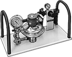
Manual Pumps for Testing and Calibration
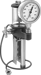 | 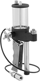 | 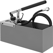 | 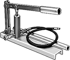 |
Style D | Style E | Style F | Style H |
Outlet | Overall | |||||||||||||
|---|---|---|---|---|---|---|---|---|---|---|---|---|---|---|
Style | For Use With | Max. Pressure Generated, psi | Pipe Size | Thread Type | Gender | Ht. | Wd. | Dp. | Body Material | Features | Each | |||
Portable | ||||||||||||||
| D | Hydraulic Fluid | 1,000 | 1/4 | NPT | Female | 14 1/4" | 4 1/2" | 4 1/2" | Plastic, Stainless Steel | Adjustable Pressure Control, Pressure Gauge (±0.5% Accuracy), Swivel Gauge Fitting | 40135K54 | 000000000 | ||
| D | Hydraulic Fluid | 2,000 | 1/4 | NPT | Female | 14 1/4" | 4 1/2" | 4 1/2" | Plastic, Stainless Steel | Adjustable Pressure Control, Pressure Gauge (±1% Accuracy), Swivel Gauge Fitting | 40135K55 | 000000 | ||
| D | Hydraulic Fluid | 3,000 | 1/4 | NPT | Female | 14 1/4" | 4 1/2" | 4 1/2" | Plastic, Stainless Steel | Adjustable Pressure Control, Pressure Gauge (±1% Accuracy), Swivel Gauge Fitting | 40135K56 | 000000 | ||
| E | Hydraulic Fluid | 3,000 | 1/4 | NPT | Female | 10 1/4" | 4 1/2" | 4 1/2" | Plastic, Stainless Steel | Adjustable Pressure Control | 40135K31 | 000000 | ||
| F | Hydraulic Fluid, Water | 360 | 1/2 | BSPT | Female | 6 1/8" | 15" | 8 1/2" | Galvanized Steel | Pressure Gauge (±2.5% Accuracy) | 9108T2 | 000000 | ||
| F | Hydraulic Fluid, Water | 860 | 1/2 | BSPT | Female | 10 1/4" | 28 1/2" | 6 5/8" | Galvanized Steel | Pressure Gauge (±2.5% Accuracy) | 9108T3 | 000000 | ||
Stationary with 3/4 GHT Female Inlet | ||||||||||||||
| H | Hydraulic Fluid, Water | 6,000 | 1/4 | NPT | Female | 13 1/2" | 24" | 9" | Bronze | Channel Base | 4160K16 | 00000000 | ||
Air-Powered Test Pumps
 | 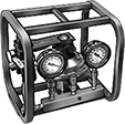 | 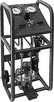 |
Style A | Style B | Style C |
Outlet | Air Connection | Overall | Material | |||||||||||||||||
|---|---|---|---|---|---|---|---|---|---|---|---|---|---|---|---|---|---|---|---|---|
Style | For Use With | Max. Pressure Generated, psi | Max. Input Pressure, psi | Max. Flow Rate, gpm | Pipe Size | Thread Type | Gender | Pipe Size | Thread Type | Gender | Ht. | Wd. | Dp. | Body | Frame | Features | Each | |||
Stationary with 3/4 GHT Female Inlet | ||||||||||||||||||||
| A | Hydraulic Fluid, Water | 1,000 | 100 | 1.38 | 3/8 | NPT | Female | 3/8 | NPT | Female | 12" | 23" | 12" | Stainless Steel | Steel | Pressure Regulating Valve, Removable Roll Bars, Two Pressure Gauges (±0.5% Accuracy), Regulator | 41455K81 | 000000000 | ||
| A | Hydraulic Fluid, Water | 3,000 | 100 | 0.28 | 3/8 | NPT | Female | 3/8 | NPT | Female | 12" | 23" | 12" | Stainless Steel | Steel | Pressure Regulating Valve, Removable Roll Bars, Two Pressure Gauges (±0.5% Accuracy), Regulator | 41455K83 | 00000000 | ||
| A | Hydraulic Fluid, Water | 6,000 | 100 | 0.29 | 3/8 | NPT | Female | 3/8 | NPT | Female | 12" | 23" | 12" | Stainless Steel | Steel | Pressure Regulating Valve, Removable Roll Bars, Two Pressure Gauges (±0.5% Accuracy), Regulator | 41455K85 | 00000000 | ||
| A | Hydraulic Fluid, Water | 10,000 | 100 | 0.2 | 3/8 | NPT | Female | 3/8 | NPT | Female | 12" | 23" | 12" | Stainless Steel | Steel | Pressure Regulating Valve, Removable Roll Bars, Two Pressure Gauges (±0.5% Accuracy), Regulator | 41455K87 | 00000000 | ||
| B | Hydraulic Fluid, Water | 1,000 | 100 | 1.38 | 3/8 | NPT | Female | 3/8 | NPT | Female | 15" | 15" | 15" | Stainless Steel | Steel | Pressure Regulating Valve, Two Pressure Gauges (±0.5% Accuracy), Regulator, Roll Bars | 41465K71 | 00000000 | ||
| B | Hydraulic Fluid, Water | 3,000 | 100 | 0.28 | 3/8 | NPT | Female | 3/8 | NPT | Female | 15" | 15" | 15" | Stainless Steel | Steel | Pressure Regulating Valve, Two Pressure Gauges (±0.5% Accuracy), Regulator, Roll Bars | 41465K73 | 00000000 | ||
| B | Hydraulic Fluid, Water | 6,000 | 100 | 0.29 | 3/8 | NPT | Female | 3/8 | NPT | Female | 15" | 15" | 15" | Stainless Steel | Steel | Pressure Regulating Valve, Two Pressure Gauges (±0.5% Accuracy), Regulator, Roll Bars | 41465K75 | 00000000 | ||
| B | Hydraulic Fluid, Water | 10,000 | 100 | 0.2 | 3/8 | NPT | Female | 3/8 | NPT | Female | 15" | 15" | 15" | Stainless Steel | Steel | Pressure Regulating Valve, Two Pressure Gauges (±0.5% Accuracy), Regulator, Roll Bars | 41465K77 | 00000000 | ||
Rolling with 3/8 NPT Female Inlet | ||||||||||||||||||||
| C | Hydraulic Fluid, Water | 1,000 | 100 | 1.38 | 3/8 | NPT | Female | 3/8 | NPT | Female | 36" | 15" | 15" | Stainless Steel | Steel | Pressure Regulating Valve, Two Pressure Gauges (±0.5% Accuracy), Regulator, Roll Bars | 41485K91 | 00000000 | ||
| C | Hydraulic Fluid, Water | 3,000 | 100 | 0.28 | 3/8 | NPT | Female | 3/8 | NPT | Female | 36" | 15" | 15" | Stainless Steel | Steel | Pressure Regulating Valve, Two Pressure Gauges (±0.5% Accuracy), Regulator, Roll Bars | 41485K93 | 00000000 | ||
| C | Hydraulic Fluid, Water | 6,000 | 100 | 0.29 | 3/8 | NPT | Female | 3/8 | NPT | Female | 36" | 15" | 15" | Stainless Steel | Steel | Pressure Regulating Valve, Two Pressure Gauges (±0.5% Accuracy), Regulator, Roll Bars | 41485K95 | 00000000 | ||
| C | Hydraulic Fluid, Water | 10,000 | 100 | 0.2 | 3/8 | NPT | Female | 3/8 | NPT | Female | 36" | 15" | 15" | Stainless Steel | Steel | Pressure Regulating Valve, Two Pressure Gauges (±0.5% Accuracy), Regulator, Roll Bars | 41485K97 | 00000000 | ||
Air to Hydraulic Power Units
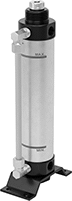 |
Power a hydraulic cylinder from your air system to avoid the setup, cost, and mess of hydraulic fluid. These converters give you more consistent power than using air power for an air cylinder. However, because air works at a lower pressure than hydraulic fluid, your hydraulic cylinder won’t move loads at its full force. Attach these converters to an air line with a speed controller and solenoid (not included).
Note: These converters are not for use near fire.
Oil Displacement, mm | Overall, mm | Inlet Connection—BSPT | Outlet Connection—BSPT | Drain Connection—BSPT | Mounting Holes | |||||||||||||||
|---|---|---|---|---|---|---|---|---|---|---|---|---|---|---|---|---|---|---|---|---|
Max. | Increments | For Max. Hydraulic Cylinder Stroke Lg., mm | Max. Flow Rate, gpm | Max. Pressure, psi | Cap., gal. | Wd. | Ht. | Pipe Size | Dash Size | Pipe Size | Dash Size | Pipe Size | Dash Size | No. of | Dia., mm | Features | Each | |||
For 40 mm Bore Dia. | ||||||||||||||||||||
| 50 | 50 | 60 | 3.3 | 100 | 0.02 | 107 | 213 | 1/4 | 06 | 1/4 | 06 | — | — | 4 | 7 | Drain Plug | 6476N11 | 000000 | ||
| 100 | 50 | 120 | 3.3 | 100 | 0.03 | 107 | 263 | 1/4 | 06 | 1/4 | 06 | — | — | 4 | 7 | Drain Plug | 6476N12 | 00000 | ||
| 150 | 50 | 180 | 3.3 | 100 | 0.05 | 107 | 313 | 1/4 | 06 | 1/4 | 06 | — | — | 4 | 7 | Drain Plug | 6476N13 | 00000 | ||
| 200 | 50 | 250 | 3.3 | 100 | 0.07 | 107 | 363 | 1/4 | 06 | 1/4 | 06 | — | — | 4 | 7 | Drain Plug | 6476N14 | 00000 | ||
For 63 mm Bore Dia. | ||||||||||||||||||||
| 50 | 50 | 150 | 7.9 | 100 | 0.04 | 104 | 228 | 3/8 | 06 | 3/4 | 12 | 1/4 | 06 | 4 | 11 | Drain Plug | 6476N15 | 00000 | ||
| 100 | 50 | 300 | 7.9 | 100 | 0.08 | 104 | 278 | 3/8 | 06 | 3/4 | 12 | 1/4 | 06 | 4 | 11 | Drain Plug | 6476N16 | 000000 | ||
| 200 | 50 | 600 | 7.9 | 100 | 0.16 | 104 | 378 | 3/8 | 06 | 3/4 | 12 | 1/4 | 06 | 4 | 11 | Drain Plug | 6476N17 | 000000 | ||
| 300 | 50 | 890 | 7.9 | 100 | 0.24 | 104 | 503 | 3/8 | 06 | 3/4 | 12 | 1/4 | 06 | 4 | 11 | Drain Plug | 6476N18 | 000000 | ||
Slim-Shaft Hydraulic Power Units
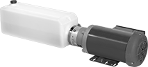 | 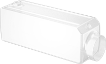 |
Replacement Hydraulic Tanks |
Hydraulic Power Units | Replacement Hydraulic Tanks | ||||||||||||||||
|---|---|---|---|---|---|---|---|---|---|---|---|---|---|---|---|---|---|
Overall | Inlet Connection — NPT | Outlet Connection — NPT | |||||||||||||||
Max. Flow Rate, gpm | Max. Pressure, psi | Power, hp | Cap., gal. | Lg. | Wd. | Ht. | Pipe Size | Dash Size | Pipe Size | Dash Size | Full Load Current @ Voltage | Each | Each | ||||
120V AC/240V AC, Single Phase | |||||||||||||||||
| 1 | 2,500 | 2 | 2.3 | 36 1/8" | 8 1/8" | 8 5/8" | 1/4 | 04 | 3/8 | 06 | 10 amp @ 240V AC | 3973K41 | 000000000 | 3973K415 | 0000000 | ||
| 1.5 | 2,500 | 2 | 2.3 | 34 7/8" | 8 1/8" | 8 5/8" | 1/4 | 04 | 3/8 | 06 | 10 amp @ 240V AC | 3973K42 | 00000000 | 3973K415 | 000000 | ||
