


Filter by
For Use With
Set Pressure
Maximum Pressure
Valve Type
Valve Function
Connection Port
Body Material
Thread Type
Actuation
Maximum Inlet Pressure
Set Pressure Configuration
Manufacturer Equivalent
Minimum Pressure
Adjustability
Shape
REACH
DFARS Specialty Metals
Pressure-Regulating Inline Hydraulic Valves
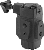 |
When input pressure varies, use these valves to maintain a consistent pressure. They are often placed after a directional-control valve and before an actuator, such as a cylinder. They have an indicator/gauge port for the inlet and one for the outlet so you can monitor that output pressure remains steady.
Inlet/Outlet Connection | Relief Connection | Overall | ||||||||||||
|---|---|---|---|---|---|---|---|---|---|---|---|---|---|---|
Pipe Size | Dash Size | Pipe Size | Dash Size | Max. Flow Rate, gpm | Max. Pressure, psi | Lg. | Wd. | Ht. | For Use With | Choose a Set Pressure, psi | Each | |||
NPT Female Inlet and Relief Port | ||||||||||||||
Cast Iron Body—Buna-N Seal | ||||||||||||||
| 3/4 | 12 | 1/4 | 04 | 33 | 3,000 | 5 7/8" | 3 3/4" | 7 1/8" | Hydraulic Fluid | 100 to 1,000, 500 to 2,000, 1,000 to 3,000 | 9474T2 | 0000000 | ||
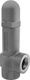
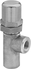
Hydraulic Pressure-Relief Valves
 |  |
Iron | 316 Stainless Steel |
To set the pressure, unscrew the cap and turn the adjustment screw. Valves begin opening at the set pressure and fully open at about 10% over the set pressure. They begin closing as pressure drops and close when the system pressure is restored below the set pressure.
Iron Body—Iron valves absorb vibration to reduce noise and wear in the pipeline.
316 Stainless Steel Body—316 stainless steel valves are more corrosion resistant than iron valves.
Inlet Connection | Relief Connection | Overall | ||||||||||
|---|---|---|---|---|---|---|---|---|---|---|---|---|
Pipe Size | Dash Size | Pipe Size | Dash Size | Lg. | Wd. | Ht. | Temp. Range, ° F | Choose a Set Pressure, psi | Each | |||
NPT Female Inlet and NPT Female Relief Port | ||||||||||||
Iron Body | ||||||||||||
| 3/8 | 06 | 3/8 | 06 | 2 1/16" | 1 3/8" | 5 3/8" | -20 to 400 | 3 to 10, 7 to 35, 30 to 100, 60 to 175, 150 to 350, 300 to 500 | 4704K32 | 0000000 | ||
| 1/2 | 08 | 1/2 | 08 | 2 5/16" | 1 7/16" | 6 3/16" | -20 to 400 | 3 to 10, 7 to 35, 30 to 100, 60 to 175, 150 to 350, 300 to 500 | 4704K11 | 000000 | ||
| 3/4 | 12 | 3/4 | 12 | 2 11/16" | 1 11/16" | 6 15/16" | -20 to 400 | 3 to 10, 7 to 35, 30 to 100, 60 to 175, 150 to 350, 300 to 500 | 4704K12 | 000000 | ||
| 1 | 16 | 1 | 16 | 3 5/16" | 2 1/16" | 8 1/4" | -20 to 400 | 3 to 10, 7 to 35, 30 to 100, 60 to 175, 150 to 350, 300 to 500 | 4704K13 | 000000 | ||
| 1 1/4 | 20 | 1 1/4 | 20 | 3 13/16" | 2 1/2" | 9 9/16" | -20 to 400 | 3 to 10, 7 to 35, 30 to 100, 60 to 175, 150 to 350, 300 to 500 | 4704K14 | 000000 | ||
| 1 1/2 | 24 | 1 1/2 | 24 | 4 1/8" | 2 7/8" | 11 1/16" | -20 to 400 | 3 to 10, 7 to 35, 30 to 100, 60 to 175, 150 to 350, 300 to 500 | 4704K25 | 000000 | ||
| 2 | 32 | 2 | 32 | 4 5/8" | 3 1/4" | 13" | -20 to 400 | 3 to 10, 7 to 35, 30 to 100, 60 to 175, 150 to 350, 250 to 600 | 4704K26 | 000000 | ||
NPT Male Inlet and NPT Female Relief Port | ||||||||||||
316 Stainless Steel Body | ||||||||||||
| 1/2 | 08 | 1/2 | 08 | 1 5/8" | 1 1/8" | 4 3/16" | 40 to 250 | 30 to 100, 101 to 400, 401 to 1,000, 1,001 to 2,000 | 5027K11 | 000000 | ||
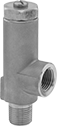
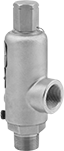
Easy-Adjust Hydraulic Pressure-Relief Valves
 |  |
Brass | 303 Stainless Steel |
An external nut lets you adjust the pressure without disassembling the valve. These valves begin opening at the set pressure and fully open at about 10% over the set pressure. They begin closing as pressure drops and fully close when the system pressure is restored below the set pressure.
Brass Body—Brass valves have good corrosion resistance.
303 Stainless Steel Body—303 stainless steel valves are more corrosion resistant than brass valves.
Inlet Connection | Relief Connection | Overall | |||||||||||||||
|---|---|---|---|---|---|---|---|---|---|---|---|---|---|---|---|---|---|
Pipe Size | Dash Size | Pipe Size | Dash Size | Max. Flow Rate, gpm | Max. Pressure, psi | Set Pressure Adjustment Method | Lg. | Wd. | Ht. | For Use With | Temp. Range, ° F | Valve Type | Choose a Set Pressure, psi | Each | |||
NPT Female Inlet and NPT Female Relief Port | |||||||||||||||||
Brass Body—Buna-N Seal | |||||||||||||||||
| 1/4 | 04 | 1/4 | 04 | 4 | 3,600 | External Adjustment Screw | 1 11/16" | 1 1/4" | 3 11/16" | Hydraulic Fluid | -40 to 250 | Relief | 4 to 15, 10 to 50, 40 to 125, 115 to 250, 235 to 450, 430 to 650, 630 to 850, 630 to 1,000, 800 to 1,500, 1,400 to 2,100, 1,500 to 2,750, 2,000 to 3,100, 3,000 to 3,600 | 4706K53 | 0000000 | ||
| 1/2 | 08 | 1/2 | 08 | 10 | 3,600 | External Adjustment Screw | 2 3/8" | 1 3/4" | 5 7/8" | Hydraulic Fluid | -40 to 250 | Relief | 4 to 15, 10 to 50, 40 to 125, 115 to 250, 235 to 450, 430 to 650, 630 to 850, 630 to 1,000, 800 to 1,500, 1,400 to 2,100, 1,500 to 2,750, 2,000 to 3,100, 3,000 to 3,600 | 4706K57 | 000000 | ||
| 3/4 | 12 | 3/4 | 12 | 15 | 3,600 | External Adjustment Screw | 2 7/16" | 1 3/4" | 5 15/16" | Hydraulic Fluid | -40 to 250 | Relief | 4 to 15, 10 to 50, 40 to 125, 115 to 250, 235 to 450, 430 to 650, 630 to 850, 630 to 1,000, 800 to 1,500, 1,400 to 2,100, 1,500 to 2,750, 2,000 to 3,100, 3,000 to 3,600 | 4706K59 | 000000 | ||
303 Stainless Steel Body—Buna-N Seal | |||||||||||||||||
| 1/2 | 08 | 1/2 | 08 | 10 | 3,600 | External Adjustment Screw | 2 3/8" | 1 3/4" | 5 7/8" | Hydraulic Fluid | -40 to 250 | Relief | 4 to 15, 10 to 50, 40 to 125 | 4706K67 | 00000000 | ||
| 3/4 | 12 | 3/4 | 12 | 15 | 3,600 | External Adjustment Screw | 2 7/16" | 1 3/4" | 5 15/16" | Hydraulic Fluid | -40 to 250 | Relief | 4 to 15, 10 to 50, 40 to 125 | 4706K69 | 00000000 | ||
Made-to-Order Pressure-Relief Valves
NPT Female Inlet and Relief Port
 |
For Use With—To Order: Please specify medium and a set pressure in 1 psi increments from the range listed in the table.
Inlet | Relief | |||||||||||||
|---|---|---|---|---|---|---|---|---|---|---|---|---|---|---|
Pipe Size | Location | Max. Pressure, psi | Port Pipe Size | Port Location | Choose a Set Pressure, psi | Shape | Overall Ht. | Temp. Range, ° F | Valve Type | For Use With | Each | |||
316 Stainless Steel Body—Fluoroelastomer Seal | ||||||||||||||
| 1/2 | Bottom | 3,300 | 3/4 | Side | 150 to 2,699 | 90° Elbow | 7 1/2" | -10 to 400 | Relief | Hydraulic Oil | 6871K41 | 000000000 | ||
NPT Male Inlet and NPT Female Relief Port
|
For Use With—To Order: Please specify medium and a set pressure in 1 psi increments from the range listed in the table.
Inlet | Relief | |||||||||||||
|---|---|---|---|---|---|---|---|---|---|---|---|---|---|---|
Pipe Size | Location | Max. Pressure, psi | Port Pipe Size | Port Location | Choose a Set Pressure, psi | Shape | Overall Ht. | Temp. Range, ° F | Valve Type | For Use With | Each | |||
316 Stainless Steel Body—Fluoroelastomer Seal | ||||||||||||||
| 3/4 | Bottom | 3,300 | 3/4 | Side | 150 to 2,269 | 90° Elbow | 7 1/2" | -10 to 400 | Relief | Hydraulic Oil | 6871K51 | 000000000 | ||
| 1 | Bottom | 3,300 | 1 | Side | 150 to 2,421 | 90° Elbow | 7 1/2" | -10 to 400 | Relief | Hydraulic Oil | 6871K61 | 00000000 | ||
Screw-In Hydraulic Pressure-Relief Valves
Set a specific pressure and these valves will maintain it. Also known as cartridge valves, these compact valves screw into your mounting block. They begin opening at the set pressure and fully open at about 20% over the set pressure. They begin closing as pressure drops and fully close when the system pressure is restored below the set pressure.
Body—UN/UNF (SAE Straight) | Set Pressure | |||||||||||||
|---|---|---|---|---|---|---|---|---|---|---|---|---|---|---|
Deltrol Equivalent Model No. | Hydraforce Equivalent Model No. | Thread Size | Dash Size | Max. Flow Rate, gpm | Max. Pressure, psi | Range, psi | Adjustment Method | Overall Ht. | For Use With | Valve Type | Each | |||
Inlet Relief Port | ||||||||||||||
Anodized Aluminum Body—Buna-N Seal | ||||||||||||||
| DRV2-080-N-K-4 | — | 3/4"-16 | 08 | 10 | 3,000 | 100 to 400 | Knob | 4" | Hydraulic Fluid | Relief | 1628N11 | 000000 | ||
| DRV2-080-N-K-20 | — | 3/4"-16 | 08 | 10 | 3,000 | 300 to 2,000 | Knob | 4" | Hydraulic Fluid | Relief | 1628N12 | 00000 | ||
| DRV2-080-N-K-30 | — | 3/4"-16 | 08 | 10 | 3,000 | 1,500 to 3,000 | Knob | 4" | Hydraulic Fluid | Relief | 1628N13 | 00000 | ||
| DRV-100-N-K-4 | RV10-20A-0-N | 7/8"-14 | 10 | 10 | 3,000 | 100 to 400 | Knob | 4 1/2" | Hydraulic Fluid | Relief | 1628N14 | 00000 | ||
| DRV-100-N-K-20 | RV10-20A-0-N | 7/8"-14 | 10 | 10 | 3,000 | 300 to 2,000 | Knob | 4 1/2" | Hydraulic Fluid | Relief | 1628N15 | 00000 | ||
| DRV-100-N-K-30 | RV10-20A-0-N | 7/8"-14 | 10 | 10 | 3,000 | 1,500 to 3,000 | Knob | 4 1/2" | Hydraulic Fluid | Relief | 1628N16 | 00000 | ||
Pressure-Regulating Block-Mount Hydraulic Valves
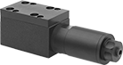 |  |
D03 Mounting Pattern |
These valves maintain consistent pressure when input pressure varies. They're often placed after a directional-control valve and before an actuator, such as a cylinder. The D03 mounting pattern attaches directly to standard NFPA subplates, simplifying valve swaps and system layout. Fluoroelastomer seals resist high temperatures and aggressive fluids better than standard Buna-N seals. Use screws to attach to an NFPA valve-mounting block (each component sold separately).
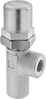
Tamper-Resistant Hydraulic Pressure-Relief Valves
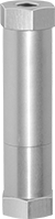 |
The pressure setting on these valves cannot be adjusted while they are installed. Use a hex key to unlock the locknut and turn the adjustment screw to set the pressure. Valves begin opening at the set pressure and fully open at about 10% over the set pressure. They begin closing as pressure drops and fully close when the system pressure is restored below the set pressure.
Inlet Connection | Relief Connection | Overall | ||||||||||
|---|---|---|---|---|---|---|---|---|---|---|---|---|
Pipe Size | Dash Size | Pipe Size | Dash Size | Wd. | Ht. | For Use With | Temp. Range, ° F | Choose a Set Pressure, psi | Each | |||
NPT Female Inlet and NPT Female Relief Port | ||||||||||||
Aluminum Body | ||||||||||||
| 1/2 | 08 | 1/2 | 08 | 1 1/4" | 5" | Hydraulic Fluid | -40 to 250 | 40 to 125, 115 to 250, 235 to 450, 630 to 850, 630 to 1,000, 800 to 1,500, 1,400 to 2,100 | 5026K16 | 000000000 | ||
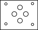
Block-Mount Hydraulic Pressure-Relief Valves
| |
D03 Mounting Pattern |
Set a specific pressure and this valve will maintain it by diverting excess fluid from a pump to a tank. Valve opens at set pressure and closes when pressure drops. Use screws to attach to an NFPA valve-mounting block (each component sold separately).
Valves | Screws | ||||||||||||||||
|---|---|---|---|---|---|---|---|---|---|---|---|---|---|---|---|---|---|
Set Pressure | Overall | ||||||||||||||||
NFPA Mounting Pattern | ISO Mounting Pattern | Max. Flow Rate, gpm | Max. Pressure, psi | Range, psi | Adjustment Method | Lg. | Wd. | Ht. | For Use With | Valve Type | Each | Pkg. Qty. | Pkg. | ||||
Inlet Relief Port | |||||||||||||||||
Fluoroelastomer Seal | |||||||||||||||||
| D03 | 03 | 6.5 | 5,000 | 265 to 3,000 | External Adjustment Screw | 6 5/8" | 1 7/8" | 2" | Hydraulic Fluid | Relief | 1624N11 | 000000000 | 4 | 1945N14 | 00000 | ||
