


Filter by
System of Measurement
Capacity
For Use With
Total Number of Ports
Maximum Temperature
Cover Style
Connection Port
Length
Mounting Hole Diameter
Bowl Material
Hydraulic Tank Type
Bowl Diameter
Flow Control Type
Number of Ports
Clarity

DFARS Specialty Metals
Export Control Classification Number (ECCN)
Hydraulic Tanks
 |
Style A |
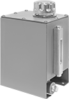
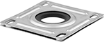
Store fluids for a hydraulic power unit or circulating-oil system. Choose a tank capacity about three times greater than your requirement to allow for heat dissipation. Tanks with only a drain connection require you to drill your own inlet/outlet connection and add pipe suction flanges (sold separately). Flanges seal pipes that pass through the top plate of your tank.
Overall | Drain | Mounting | |||||||||||||
|---|---|---|---|---|---|---|---|---|---|---|---|---|---|---|---|
Style | Cap., gal. | Lg. | Wd. | Ht. | Pipe Size | Dash Size | No. of Ports | Fasteners Included | No. of Holes | Hole Dia. | Max. Temp., ° F | Each | |||
Steel | |||||||||||||||
Single Chamber Tanks | |||||||||||||||
| A | 1 | 6" | 7 1/2" | 12 1/4" | 1/2 NPT | 08 | 1 | No | 4 | 11/32" | 250 | 1149K11 | 0000000 | ||
 |
Mounting Hole | ||||||||||
|---|---|---|---|---|---|---|---|---|---|---|
For Pipe Size | For Cutout Dia. | Material | Mounting Fasteners Included | Ctr.-to-Ctr. | Lg | Wd. | Includes | Each | ||
| 1/2 | 4 5/16" | Steel | Yes | 4 1/4" | 7/8" | 7/16" | Top Plate, Bottom Plate, Gasket, Washer | 62875K21 | 000000 | |
| 3/4 | 4 5/16" | Steel | Yes | 4 1/4" | 7/8" | 7/16" | Top Plate, Bottom Plate, Gasket, Washer | 62875K22 | 00000 | |
| 1 1/4 | 4 5/16" | Steel | Yes | 4 1/4" | 7/8" | 7/16" | Top Plate, Bottom Plate, Gasket, Washer | 62875K23 | 00000 | |
| 1 1/2 | 4 5/16" | Steel | Yes | 4 1/4" | 7/8" | 7/16" | Top Plate, Bottom Plate, Gasket, Washer | 62875K24 | 00000 | |
| 2 | 4 5/16" | Steel | Yes | 4 1/4" | 7/8" | 7/16" | Top Plate, Bottom Plate, Gasket, Washer | 62875K25 | 00000 | |
 |
Flange Mount |
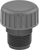
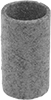
Breather vents prevent excess pressure in tanks and allow a free flow of air.
Material | Strainer | Mounting Hole | ||||||||||||||
|---|---|---|---|---|---|---|---|---|---|---|---|---|---|---|---|---|
For Cutout Dia. | Cap | Strainer | Gasket | Removes Particle Size Down To, μm | Cap Dia. | Flange Dia. | Dia | Ht. | Mounting Fasteners Included | Lg. | Wd. | Bolt Circle Dia. | Mount Type | Each | ||
| 2 1/8" | Zinc-Plated Steel | Plastic | Rubber | 40 | 3" | 3 1/4" | 1 7/8" | 3 13/16" | Yes | 1/4" | 3/16" | 2 7/8" | Flange | 62875K13 | 000000 | |
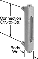 |
Aluminum |
Thread | ||||||||||||||||
|---|---|---|---|---|---|---|---|---|---|---|---|---|---|---|---|---|
Size | Type | Gender | Connection Ctr.-to-Ctr. | Overall Ht. | Window Ht. | Body Wd. | For Max. Tank Wall Thk. | Max. Pressure @ Temp. | Temp. Range, ° F | Material | Fitting Material | Window Material | Includes | Each | ||
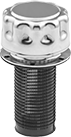
| 1/2"-20 | UNF | Male | 5" | 6 5/8" | 3 1/2" | 7/8" | 3/4" | 290 psi @ 70° F | -40 to 250 | Aluminum | Aluminum | Glass | Mounting Nuts | 1106K85 | 000000 | |
Oil Reservoirs
140° F Maximum Temperature
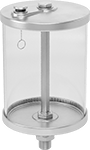 |
Reservoirs with 140° F max. temp. have NPTF (Dryseal) threads, which are compatible with NPT threads. Flow rate depends on temperature.
For Max. Viscosity | |||||||||||||
|---|---|---|---|---|---|---|---|---|---|---|---|---|---|
Cap., gal. | Bowl Dia. | Overall Ht. | Housing Material | Bowl Material | Pressure Regulation Method | ISO Grade | SAE Grade | SSU Grade | AGMA Grade | Each | |||
3/8 NPTF Male Outlet | |||||||||||||
| 1 | 5 1/2" | 14 15/16" | Aluminum | Plastic | Vented | Not Rated | Not Rated | Not Rated | Not Rated | 1169K45 | 0000000 | ||
1/2 NPTF Male Outlet | |||||||||||||
| 1 | 5 1/2" | 15 1/4" | Aluminum | Plastic | Vented | Not Rated | Not Rated | Not Rated | Not Rated | 1169K46 | 000000 | ||
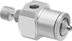
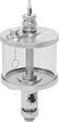
Oil Dispensers with Flow-Adjustment Valve
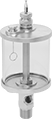 |
Thread these dispensers directly into bearing housings, pumps, and other machinery. Flip the lever to start and stop flow; turn the dial to adjust flow. They have NPTF (Dryseal) threads, which are compatible with NPT threads.
For Max. Viscosity | ||||||||||||||
|---|---|---|---|---|---|---|---|---|---|---|---|---|---|---|
Cap., gal. | Bowl Dia. | Overall Ht. | Housing Material | Bowl Material | Pressure Regulation Method | ISO Grade | SAE Grade | SSU Grade, SSU | AGMA Grade | Features | Each | |||
160° F Maximum Temperature | ||||||||||||||
1/2 NPTF Male Oil Outlet | ||||||||||||||
| 1 | 5 1/2" | 17 1/16" | Aluminum | Plastic | Vented | 320 | 90 | 1,500 | 6 | Glass Flow Sight | 1167K19 | 0000000 | ||
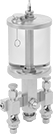
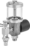
Air-Powered Oil Dispensers
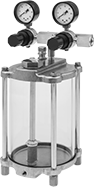 |
Connect these dispensers to your air system to pressurize the oil in the reservoir and atomize the spray. Dual regulators allow you to adjust the pressure of the oil and the atomized spray. Add a spray valve (sold separately) to direct the flow of oil. A removable filter prevents valve blockage. They have NPTF (Dryseal) threads, which are compatible with NPT threads.
Overall | Air Inlet | Air Outlet | ||||||||||||||||
|---|---|---|---|---|---|---|---|---|---|---|---|---|---|---|---|---|---|---|
Cap., gal. | Max. Oil Outlet Pressure, psi | Ht. | Wd. | Dp. | Max. Air Inlet Pressure, psi | Thread Type | Pipe Size | Gender | Thread Type | Pipe Size | Gender | Temp. Range, ° F | Mounting Hole Thread Size | For Max. ISO Viscosity Grade | Each | |||
1/8 NPTF Female Oil Outlet | ||||||||||||||||||
| 1 | 30 | 19 1/4" | 5 13/16" | 5 13/16" | 125 | NPTF | 1/4 | Female | NPTF | 1/8 | Female | -30 to 140 | 5/16"-24 | 150 | 12745K54 | 0000000 | ||
Multiple-Outlet Oil Dispensers with Flow-Adjustment Valves
 | 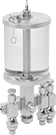 | 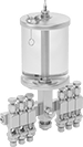 |
2 Outlets | 3 Outlets | 6 Outlets |
Serve multiple lubrication points from a single location. Adjust the flow to individual lubrication points by turning the dial on the corresponding valve. Change the reservoir flow by turning the dial on the bowl. Flip the lever to start and stop flow to all of the valves at once. Dispensers can be used with any oil grade. Flow rate depends on temperature.
Overall | |||||||||||||
|---|---|---|---|---|---|---|---|---|---|---|---|---|---|
Cap., gal. | Bowl Dia. | Ht. | Wd. | Housing Material | Bowl Material | Pressure Regulation Method | Max. Temp., ° F | Mounting Thread Size | Features | Each | |||
2 Oil Outlets—For 1/4" OD Oil Outlet Tubes | |||||||||||||
| 1 | 5 1/2" | 19 1/16" | 4 3/8" | Aluminum | Plastic | Vented | 140 | 5/8"-18 | Glass Flow Sight | 1067K16 | 0000000 | ||
3 Oil Outlets—For 1/4" OD Oil Outlet Tubes | |||||||||||||
| 1 | 5 1/2" | 19 1/16" | 5 1/8" | Aluminum | Plastic | Vented | 140 | 5/8"-18 | Glass Flow Sight | 1067K36 | 000000 | ||
6 Oil Outlets—For 1/4" OD Oil Outlet Tubes | |||||||||||||
| 1 | 5 1/2" | 19 1/16" | 7 3/8" | Aluminum | Plastic | Vented | 140 | 5/8"-18 | Glass Flow Sight | 1067K56 | 000000 | ||
Remote-Access Oil Dispensers with Flow-Adjustment Valve
 |
Connect a tube fitting and tubing (not included) to the dispenser outlet to access hard-to-reach lubrication points. Flip the lever to start and stop flow; turn the dial to adjust flow. They have NPTF (Dryseal) threads, which are compatible with NPT threads.
For Max. Viscosity | ||||||||||||||||
|---|---|---|---|---|---|---|---|---|---|---|---|---|---|---|---|---|
Cap., gal. | Bowl Dia. | Overall Ht. | Housing Material | Bowl Material | Pressure Regulation Method | Mounting Thread Size | ISO Grade | SAE Grade | SSU Grade, SSU | AGMA Grade | Features | Includes | Each | |||
160° F Maximum Temperature | ||||||||||||||||
1/8 NPTF Female Oil Outlet | ||||||||||||||||
| 1 | 5 1/2" | 16 5/16" | Aluminum | Plastic | Vented | 5/8"-18 | 320 | 90 | 1,500 | 6 | Glass Flow Sight | Nut, Washer | 1175K15 | 0000000 | ||
Bladder-Style Hydraulic Accumulators
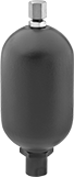 |
Charge these accumulators to the pressure you need, and they will help a system maintain a constant pressure during pump failure. Mount accumulators within 25° of vertical. UN/UNF (SAE Straight) thread connections have straight threads and are also known as O-ring Boss fittings.
Note: For safety, do not disassemble accumulators while they're under pressure.
Accumulators | Replacement Bladders | |||||||||||||||||
|---|---|---|---|---|---|---|---|---|---|---|---|---|---|---|---|---|---|---|
Inlet/Outlet Connection for Hydraulic Fluid | Inlet/Outlet Connection for Nitrogen | Body | ||||||||||||||||
Cap., gal. | Max. Flow Rate, gpm | Max. Pressure, psi | Thread Size | Thread Type | Gender | Dash Size | Valve Type | Gender | Overall Ht. | Ht. | Dia. | Mounting Position | Each | Each | ||||
Steel Body with Buna-N Bag and Buna-N Seal | ||||||||||||||||||
| 1 | 150 | 3,000 | 1 5/8"-12 | UN/UNF (SAE Straight) | Female | 20 | Schrader | Male | 17" | 11 3/8" | 6 3/4" | Vertical | 59595K12 | 000000000 | 59595K32 | 0000000 | ||
Multiple-Outlet Electrically Operated Oil Dispensers with Flow-Adjustment Valves
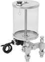 | 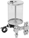 | 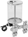 | 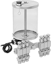 |
2 Outlets | 3 Outlets | 4 Outlets | 6 Outlets |
Overall | |||||||||||||||
|---|---|---|---|---|---|---|---|---|---|---|---|---|---|---|---|
Cap., gal. | Bowl Dia. | Ht. | Wd. | Housing Material | Bowl Material | Pressure Regulation Method | Max. Temp., ° F | Mounting Thread Size | Features | Electrical Connection Type | Wire Connection | Each | |||
120V AC 0.1 amp | |||||||||||||||
2 Oil Outlets—For 1/4" OD Oil Outlet Tubes | |||||||||||||||
| 1 | 5 1/2" | 16 3/4" | 4 3/8" | Aluminum | Plastic | Vented | 140 | 5/8"-18 | Glass Flow Sight | Hardwire | Wire Leads | 1065K16 | 0000000 | ||
3 Oil Outlets—For 1/4" OD Oil Outlet Tubes | |||||||||||||||
| 1 | 5 1/2" | 16 3/4" | 5" | Aluminum | Plastic | Vented | 140 | 5/8"-18 | Glass Flow Sight | Hardwire | Wire Leads | 1065K36 | 000000 | ||
4 Oil Outlets—For 1/4" OD Oil Outlet Tubes | |||||||||||||||
| 1 | 5 1/2" | 16 3/4" | 5 7/8" | Aluminum | Plastic | Vented | 140 | 5/8"-18 | Glass Flow Sight | Hardwire | Wire Leads | 1065K46 | 000000 | ||
6 Oil Outlets—For 1/4" OD Oil Outlet Tubes | |||||||||||||||
| 1 | 5 1/2" | 16 3/4" | 7 3/8" | Aluminum | Plastic | Vented | 140 | 5/8"-18 | Glass Flow Sight | Hardwire | Wire Leads | 1065K66 | 000000 | ||
24V DC 0.4 amp | |||||||||||||||
2 Oil Outlets—For 1/4" OD Oil Outlet Tubes | |||||||||||||||
| 1 | 5 1/2" | 16 3/4" | 4 3/8" | Aluminum | Plastic | Vented | 140 | 5/8"-18 | Glass Flow Sight | Hardwire | Wire Leads | 1065K26 | 000000 | ||
3 Oil Outlets—For 1/4" OD Oil Outlet Tubes | |||||||||||||||
| 1 | 5 1/2" | 16 3/4" | 5" | Aluminum | Plastic | Vented | 140 | 5/8"-18 | Glass Flow Sight | Hardwire | Wire Leads | 1065K86 | 000000 | ||
4 Oil Outlets—For 1/4" OD Oil Outlet Tubes | |||||||||||||||
| 1 | 5 1/2" | 16 3/4" | 5 7/8" | Aluminum | Plastic | Vented | 140 | 5/8"-18 | Glass Flow Sight | Hardwire | Wire Leads | 1065K56 | 000000 | ||
6 Oil Outlets—For 1/4" OD Oil Outlet Tubes | |||||||||||||||
| 1 | 5 1/2" | 16 3/4" | 7 3/8" | Aluminum | Plastic | Vented | 140 | 5/8"-18 | Glass Flow Sight | Hardwire | Wire Leads | 1065K76 | 000000 | ||
Electrically Operated Oil Dispensers with Flow-Adjustment Valve
 |
A solenoid automatically starts and stops flow to dispense lubricant only while equipment is running. When wired to a machine’s on/off switch, the solenoid remains closed until the machine is turned on. Turn the dial on the valve to adjust flow. Dispensers can be used with any oil grade. Flow rate depends on temperature.
Charged Bladder-Style Hydraulic Accumulators
|
These accumulators come with a charge of nitrogen and are ready to use. They help a system maintain a constant pressure during pump failure. Mount accumulators within 25° of vertical. UN/UNF (SAE Straight) thread connections have straight threads and are also known as O-ring Boss fittings.
Note: For safety, do not disassemble accumulators while they're under pressure.
Accumulators | Replacement Bladders | ||||||||||||||||||
|---|---|---|---|---|---|---|---|---|---|---|---|---|---|---|---|---|---|---|---|
Inlet/Outlet Connection for Hydraulic Fluid | Inlet/Outlet Connection for Nitrogen | Body | |||||||||||||||||
Cap., gal. | Max. Flow Rate, gpm | Max. Pressure, psi | Nitrogen Charge, psi | Thread Size | Thread Type | Gender | Dash Size | Valve Type | Gender | Overall Ht. | Ht. | Dia. | Mounting Position | Each | Each | ||||
Steel Body with Buna-N Bag and Buna-N Seal | |||||||||||||||||||
| 1 | 150 | 3,000 | 2,100 | 1 5/8"-12 | UN/UNF (SAE Straight) | Female | 20 | Schrader | Male | 17" | 11 3/8" | 6 3/4" | Vertical | 59595K43 | 000000000 | 59595K32 | 0000000 | ||
