


Filter by
Capacity
For Use With
Hydraulic Tank Type
Overall Height
Height
Maximum Temperature
Thread Type
Cover Style
Export Control Classification Number (ECCN)
DFARS Specialty Metals
Hydraulic Tanks
 |  |
Style B | Style C |
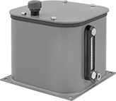
Store fluids for a hydraulic power unit or circulating-oil system. Choose a tank capacity about three times greater than your requirement to allow for heat dissipation. Tanks with only a drain connection require you to drill your own inlet/outlet connection and add pipe suction flanges (sold separately). Flanges seal pipes that pass through the top plate of your tank.
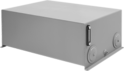
Dual Chamber Tanks—Dual chamber tanks have a divider that allows particles to settle on one side before fluid is returned to your line.
Style C—To install the breather vent to Style C tanks, drill a hole in the tank.
Overall | Drain | Mounting | |||||||||||||
|---|---|---|---|---|---|---|---|---|---|---|---|---|---|---|---|
Style | Cap., gal. | Lg. | Wd. | Ht. | Pipe Size | Dash Size | No. of Ports | Fasteners Included | No. of Holes | Hole Dia. | Max. Temp., ° F | Each | |||
Steel | |||||||||||||||
Single Chamber Tanks | |||||||||||||||
| B | 8 | 14 1/4" | 12" | 19 1/4" | 3/4 NPT | 12 | 1 | No | 4 | 7/16" | 212 | 62945K14 | 0000000 | ||
| B | 10 | 19" | 14 7/8" | 15 1/4" | 3/4 NPT | 12 | 1 | No | 4 | 7/16" | 212 | 62945K15 | 000000 | ||
Dual Chamber Tanks | |||||||||||||||
| C | 20 | 26" | 16" | 15 3/4" | 3/4 NPT | 12 | 1 | No | 4 | 1/2" | 212 | 62945K42 | 000000 | ||
| C | 30 | 26" | 16" | 21 3/4" | 3/4 NPT | 12 | 1 | No | 4 | 1/2" | 212 | 62945K43 | 000000 | ||
| C | 40 | 38 1/4" | 24" | 14" | 3/4 NPT | 12 | 1 | No | 4 | 7/16" | 212 | 62945K34 | 000000 | ||
| C | 60 | 42 3/8" | 30" | 16 5/8" | 3/4 NPT | 12 | 1 | No | 4 | 7/16" | 212 | 62945K35 | 00000000 | ||
| C | 100 | 50 3/8" | 30" | 19" | 3/4 NPT | 12 | 1 | No | 4 | 7/16" | 212 | 62945K37 | 00000000 | ||
 |
Mounting Hole | ||||||||||
|---|---|---|---|---|---|---|---|---|---|---|
For Pipe Size | For Cutout Dia. | Material | Mounting Fasteners Included | Ctr.-to-Ctr. | Lg | Wd. | Includes | Each | ||
| 1/2 | 4 5/16" | Steel | Yes | 4 1/4" | 7/8" | 7/16" | Top Plate, Bottom Plate, Gasket, Washer | 62875K21 | 000000 | |
| 3/4 | 4 5/16" | Steel | Yes | 4 1/4" | 7/8" | 7/16" | Top Plate, Bottom Plate, Gasket, Washer | 62875K22 | 00000 | |
| 1 1/4 | 4 5/16" | Steel | Yes | 4 1/4" | 7/8" | 7/16" | Top Plate, Bottom Plate, Gasket, Washer | 62875K23 | 00000 | |
| 1 1/2 | 4 5/16" | Steel | Yes | 4 1/4" | 7/8" | 7/16" | Top Plate, Bottom Plate, Gasket, Washer | 62875K24 | 00000 | |
| 2 | 4 5/16" | Steel | Yes | 4 1/4" | 7/8" | 7/16" | Top Plate, Bottom Plate, Gasket, Washer | 62875K25 | 00000 | |
 |
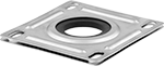
Flange Mount |
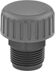
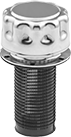
Breather vents prevent excess pressure in tanks and allow a free flow of air.
Material | Strainer | Mounting Hole | ||||||||||||||
|---|---|---|---|---|---|---|---|---|---|---|---|---|---|---|---|---|
For Cutout Dia. | Cap | Strainer | Gasket | Removes Particle Size Down To, μm | Cap Dia. | Flange Dia. | Dia | Ht. | Mounting Fasteners Included | Lg. | Wd. | Bolt Circle Dia. | Mount Type | Each | ||
| 2 1/8" | Zinc-Plated Steel | Plastic | Rubber | 40 | 3" | 3 1/4" | 1 7/8" | 3 13/16" | Yes | 1/4" | 3/16" | 2 7/8" | Flange | 62875K13 | 000000 | |
 |
Nylon With Steel Guard |
For Hole | |||||||||||||||
|---|---|---|---|---|---|---|---|---|---|---|---|---|---|---|---|
Dia. | No. of Holes | Connection Ctr.-to-Ctr. | Overall Ht. | Window Ht. | Body Wd. | For Max. Tank Wall Thk. | Max. Pressure @ Temp. | Temp. Range, ° F | Thermometer Temp. Measurement Range, ° F | Material | Guard Material | Window Material | Each | ||
| 1/2" | 2 | 5" | 6 3/8" | 3 7/8" | 13/16" | 1/2" | 50 psi @ 70° F | -40 to 210 | 0 to 220 | Nylon | Steel | Nylon | 4748K29 | 000000 | |
Hydraulic Power Units
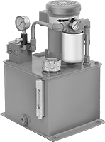 |
Create and supply hydraulic pressure. Choose a unit with a tank capacity about three times greater than your requirement to allow for heat dissipation. An inlet filter protects the pump from contamination.
All units include an additional NPTF threaded inlet port. NPTF (Dryseal) threads are compatible with NPT threads. UN/UNF (SAE Straight) thread connections have straight threads and are also known as O-ring Boss fittings.
Overall | Inlet Connection — UN/UNF (SAE Straight) | Inlet Connection — NPTF | Outlet Connection — UN/UNF (SAE Straight) | ||||||||||||||
|---|---|---|---|---|---|---|---|---|---|---|---|---|---|---|---|---|---|
Max. Flow Rate, gpm | Max. Pressure, psi | Power, hp | Cap., gal. | Lg. | Wd. | Ht. | Thread Size | Dash Size | Pipe Size | Dash Size | Thread Size | Dash Size | Full Load Current @ Voltage | Each | |||
240V AC/460V AC, Three Phase | |||||||||||||||||
| 2.7 | 1,750 | 3 | 10 | 17 3/8" | 19" | 32 1/2" | 1 1/16"-12 | 12 | 3/4 | 12 | 1 1/16"-12 | 12 | 4.4 amp @ 460V AC | 62915K33 | 000000000 | ||
| 3.6 | 2,050 | 5 | 10 | 17 3/4" | 19" | 29 3/4" | 1 1/16"-12 | 12 | 3/4 | 12 | 1 1/16"-12 | 12 | 6.8 amp @ 460V AC | 62915K44 | 00000000 | ||
| 6.3 | 1,800 | 7 1/2 | 20 | 21 3/8" | 22 1/2" | 37 3/8" | 1 1/16"-12 | 12 | 3/4 | 12 | 1 1/16"-12 | 12 | 9.5 amp @ 460V AC | 62915K36 | 00000000 | ||
| 8.6 | 1,700 | 10 | 30 | 21 3/8" | 22 1/2" | 42 1/4" | 1 1/16"-12 | 12 | 3/4 | 12 | 1 1/16"-12 | 12 | 12 amp @ 460V AC | 62915K47 | 00000000 | ||
| 10.4 | 2,100 | 15 | 30 | 23 3/8" | 22 1/2" | 44 1/8" | 1 1/16"-12 | 12 | 3/4 | 12 | 1 1/16"-12 | 12 | 18.1 amp @ 460V AC | 62915K48 | 000000000 | ||
Air to Hydraulic Power Units
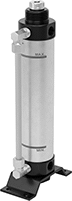 |
Power a hydraulic cylinder from your air system to avoid the setup, cost, and mess of hydraulic fluid. These converters give you more consistent power than using air power for an air cylinder. However, because air works at a lower pressure than hydraulic fluid, your hydraulic cylinder won’t move loads at its full force. Attach these converters to an air line with a speed controller and solenoid (not included).
Note: These converters are not for use near fire.
Oil Displacement, mm | Overall, mm | Inlet Connection—BSPT | Outlet Connection—BSPT | Drain Connection—BSPT | Mounting Holes | |||||||||||||||
|---|---|---|---|---|---|---|---|---|---|---|---|---|---|---|---|---|---|---|---|---|
Max. | Increments | For Max. Hydraulic Cylinder Stroke Lg., mm | Max. Flow Rate, gpm | Max. Pressure, psi | Cap., gal. | Wd. | Ht. | Pipe Size | Dash Size | Pipe Size | Dash Size | Pipe Size | Dash Size | No. of | Dia., mm | Features | Each | |||
For 63 mm Bore Dia. | ||||||||||||||||||||
| 50 | 50 | 150 | 7.9 | 100 | 0.04 | 104 | 228 | 3/8 | 06 | 3/4 | 12 | 1/4 | 06 | 4 | 11 | Drain Plug | 6476N15 | 000000 | ||
| 100 | 50 | 300 | 7.9 | 100 | 0.08 | 104 | 278 | 3/8 | 06 | 3/4 | 12 | 1/4 | 06 | 4 | 11 | Drain Plug | 6476N16 | 000000 | ||
| 200 | 50 | 600 | 7.9 | 100 | 0.16 | 104 | 378 | 3/8 | 06 | 3/4 | 12 | 1/4 | 06 | 4 | 11 | Drain Plug | 6476N17 | 000000 | ||
| 300 | 50 | 890 | 7.9 | 100 | 0.24 | 104 | 503 | 3/8 | 06 | 3/4 | 12 | 1/4 | 06 | 4 | 11 | Drain Plug | 6476N18 | 000000 | ||
Grease Dispensers
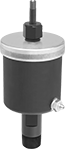 |
Steel Bowl |
A spring delivers a constant, low-pressure flow of grease to your lubrication point, so it never runs dry. They’re best for applications with consistent temperatures, so the viscosity of the grease won’t change how quickly it flows. However, they shouldn’t be used in precision applications because the tension of the spring may change, causing the dispensing rate to change. Mount them close to the lubrication point. They have a standard grease fitting, so you can choose what grease to use, unlike prefilled dispensers. The grease fitting helps close the system to keep out dust and contaminants in dirty environments such as mills. Use grease fitting adapters to match your lubrication point.
Steel Bowl—Opaque—Dispensers with a steel bowl are more durable than dispensers with a plastic bowl, so they’re the better choice if there's vibration or impact.
Grease Outlet | |||||||||||||||
|---|---|---|---|---|---|---|---|---|---|---|---|---|---|---|---|
Cap., fl. oz. | For NLGI Consistency Grade | Flow Rate | Max. Grease Outlet Pressure | Bowl Dia. | Overall Ht. | Gender | Thread Type | Pipe Size | Max. Distance from Lubrication Point | Loading Method | Temp. Range, ° F | Each | |||
Steel Bowl—Opaque | |||||||||||||||
Steel Housing | |||||||||||||||
| 8 | 1, 2, 3 | Not Rated | Not Rated | 3 1/4" | 9 3/4" | Male | NPT | 3/4 | Not Rated | Grease Gun | 32 to 160 | 1110K25 | 0000000 | ||
