


Filter by
Fitting Connection

Inlet Connection
Outlet Connection
For Use With
Flow Control Location


Body Material
Valve Function
Flow Control Type
Flow Rate @ 73 psi
Export Control Classification Number (ECCN)
U.S.–Mexico–Canada Agreement (USMCA) Qualifying
DFARS Specialty Metals

About Air Flow Control Valves
Choose a valve based on pressure, pipe size, and the direction of airflow you want to control.
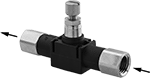
Inline Air Flow Control Valves
NPT Female Inlet × NPT Female Outlet
 |  |  |
Meter Out | Meter In |
Flow Rate @ 100 psi | ||||||||||||
|---|---|---|---|---|---|---|---|---|---|---|---|---|
Inlet Pipe Size | Outlet Pipe Size | Flow Coefficient (Cv) | Min. | Max., scfm | Max. Pressure, psi | Temp. Range, ° F | Flow Adjustment Mechanism | Flow Control Location (ISO Designation) | Each | |||
Nylon Body | ||||||||||||
| 1/8 | 1/8 | 0.118 | Not Rated | 9.1 | 145 | 35 to 155 | Dial | Exiting Cylinder (Meter Out), Entering Cylinder (Meter In) | 62005K613 | 000000 | ||
| 1/4 | 1/4 | 0.22 | Not Rated | 13.5 | 145 | 35 to 155 | Dial | Exiting Cylinder (Meter Out), Entering Cylinder (Meter In) | 62005K623 | 00000 | ||
| 3/8 | 3/8 | 0.352 | Not Rated | 20 | 145 | 35 to 155 | Dial | Exiting Cylinder (Meter Out), Entering Cylinder (Meter In) | 62005K643 | 00000 | ||
| 1/2 | 1/2 | 0.523 | Not Rated | 30.2 | 145 | 35 to 155 | Dial | Exiting Cylinder (Meter Out), Entering Cylinder (Meter In) | 62005K653 | 00000 | ||
NPT Male Inlet × Barbed Male Outlet
 | | |
Meter Out | Meter In |
Flow Rate @ 100 psi, scfm | |||||||||||
|---|---|---|---|---|---|---|---|---|---|---|---|
Inlet Pipe Size | Flow Coefficient (Cv) | Min. | Max. | Max. Pressure, psi | Temp. Range, ° F | Flow Adjustment Mechanism | Flow Control Location (ISO Designation) | Each | |||
Brass Body | |||||||||||
| 1/8 | 0.1 | 1 | 7 | 250 | -40 to 250 | Dial | Exiting Cylinder (Meter Out), Entering Cylinder (Meter In) | 6692K19 | 000000 | ||
NPTF Female Inlet × NPTF Female Outlet
| | |
Meter Out | Meter In |
Flow Rate @ 100 psi, scfm | ||||||||||||
|---|---|---|---|---|---|---|---|---|---|---|---|---|
Inlet Pipe Size | Outlet Pipe Size | Flow Coefficient (Cv) | Min. | Max. | Max. Pressure, psi | Temp. Range, ° F | Flow Adjustment Mechanism | Flow Control Location (ISO Designation) | Each | |||
Aluminum Body | ||||||||||||
| 1/8 | 1/8 | 0.8 | 1 | 47 | 250 | -40 to 250 | Dial | Exiting Cylinder (Meter Out), Entering Cylinder (Meter In) | 6692K16 | 000000 | ||
| 1/4 | 1/4 | 1.2 | 1 | 66 | 250 | -40 to 250 | Dial | Exiting Cylinder (Meter Out), Entering Cylinder (Meter In) | 6692K11 | 00000 | ||
| 3/8 | 3/8 | 2.6 | 1 | 149 | 250 | -40 to 250 | Dial | Exiting Cylinder (Meter Out), Entering Cylinder (Meter In) | 6692K12 | 00000 | ||
| 1/2 | 1/2 | 3.1 | 1 | 173 | 250 | -40 to 250 | Dial | Exiting Cylinder (Meter Out), Entering Cylinder (Meter In) | 6692K13 | 000000 | ||
UNF Male Inlet × Barbed Male Outlet
| | |
Meter Out | Meter In |
Flow Rate @ 100 psi, scfm | |||||||||||
|---|---|---|---|---|---|---|---|---|---|---|---|
Inlet Thread Size | Flow Coefficient (Cv) | Min. | Max. | Max. Pressure, psi | Temp. Range, ° F | Flow Adjustment Mechanism | Flow Control Location (ISO Designation) | Each | |||
Brass Body | |||||||||||
| 10-32 | 0.1 | 1 | 7 | 250 | -40 to 250 | Dial | Exiting Cylinder (Meter Out), Entering Cylinder (Meter In) | 6692K15 | 000000 | ||
UNF Male Inlet × UNF Female Outlet
 | | |
Meter Out | Meter In |
Flow Rate @ 100 psi, scfm | ||||||||||||
|---|---|---|---|---|---|---|---|---|---|---|---|---|
Inlet Thread Size | Outlet Thread Size | Flow Coefficient (Cv) | Min. | Max. | Max. Pressure, psi | Temp. Range, ° F | Flow Adjustment Mechanism | Flow Control Location (ISO Designation) | Each | |||
Brass Body | ||||||||||||
| 1/4"-28 | 1/4"-28 | 0.1 | 1 | 8 | 250 | -40 to 250 | Dial | Exiting Cylinder (Meter Out), Entering Cylinder (Meter In) | 6692K17 | 000000 | ||
Push-to-Connect Female Inlet × Push-to-Connect Female Outlet
 | | |
Meter Out | Meter In |
Flow Rate @ 73 psi, scfm | Flow Rate @ 100 psi, scfm | |||||||||||||
|---|---|---|---|---|---|---|---|---|---|---|---|---|---|---|
For Inlet Tube OD | For Outlet Tube OD | Flow Coefficient (Cv) | Min. | Max. | Min. | Max. | Max. Pressure, psi | Temp. Range, ° F | Flow Adjustment Mechanism | Flow Control Location (ISO Designation) | Each | |||
Polybutylene Body | ||||||||||||||
| 1/8" | 1/8" | 0.1 | 0 | 4 | — | — | 145 | 25 to 140 | Dial | Exiting Cylinder (Meter Out), Entering Cylinder (Meter In) | 62005K35 | 000000 | ||
| 5/32" | 5/32" | 0.13 | 0 | 5.2 | — | — | 145 | 25 to 140 | Dial | Exiting Cylinder (Meter Out), Entering Cylinder (Meter In) | 62005K311 | 00000 | ||
| 3/16" | 3/16" | 0.19 | — | — | 0 | 6.1 | 145 | 32 to 140 | Dial | Exiting Cylinder (Meter Out), Entering Cylinder (Meter In) | 62005K312 | 00000 | ||
| 1/4" | 1/4" | 0.19 | 0 | 9.2 | — | — | 145 | 25 to 140 | Dial | Exiting Cylinder (Meter Out), Entering Cylinder (Meter In) | 62005K313 | 00000 | ||
| 1/4" | 1/4" | 0.42 | 0 | 15.6 | — | — | 145 | 25 to 140 | Dial | Exiting Cylinder (Meter Out), Entering Cylinder (Meter In) | 62005K331 | 00000 | ||
| 1/4" | 1/4" | 0.47 | 0 | 18.4 | — | — | 145 | 25 to 140 | Dial | Exiting Cylinder (Meter Out), Entering Cylinder (Meter In) | 62005K322 | 00000 | ||
| 5/16" | 5/16" | 0.47 | 0 | 18.4 | — | — | 145 | 25 to 140 | Dial | Exiting Cylinder (Meter Out), Entering Cylinder (Meter In) | 62005K323 | 00000 | ||
| 5/16" | 5/16" | 0.67 | 0 | 26.4 | — | — | 145 | 25 to 140 | Dial | Exiting Cylinder (Meter Out), Entering Cylinder (Meter In) | 62005K332 | 00000 | ||
| 3/8" | 3/8" | 0.93 | 0 | 37 | — | — | 145 | 25 to 140 | Dial | Exiting Cylinder (Meter Out), Entering Cylinder (Meter In) | 62005K333 | 00000 | ||
| 3/8" | 3/8" | 1.06 | 0 | 37 | — | — | 145 | 25 to 140 | Dial | Exiting Cylinder (Meter Out), Entering Cylinder (Meter In) | 62005K341 | 00000 | ||
| 1/2" | 1/2" | 1.41 | 0 | 55.6 | — | — | 145 | 25 to 140 | Dial | Exiting Cylinder (Meter Out), Entering Cylinder (Meter In) | 62005K342 | 00000 | ||
| 4 mm | 4 mm | 0.13 | 0 | 5.2 | — | — | 145 | 25 to 140 | Dial | Exiting Cylinder (Meter Out), Entering Cylinder (Meter In) | 62005K611 | 00000 | ||
| 6 mm | 6 mm | 0.23 | 0 | 9.2 | — | — | 145 | 25 to 140 | Dial | Exiting Cylinder (Meter Out), Entering Cylinder (Meter In) | 62005K612 | 00000 | ||
| 6 mm | 6 mm | 0.29 | 0 | 11.6 | — | — | 145 | 25 to 140 | Dial | Exiting Cylinder (Meter Out), Entering Cylinder (Meter In) | 62005K621 | 00000 | ||
| 6 mm | 6 mm | 0.42 | 0 | 16.8 | — | — | 145 | 25 to 140 | Dial | Exiting Cylinder (Meter Out), Entering Cylinder (Meter In) | 62005K631 | 00000 | ||
| 8 mm | 8 mm | 0.47 | 0 | 18.4 | — | — | 145 | 25 to 140 | Dial | Exiting Cylinder (Meter Out), Entering Cylinder (Meter In) | 62005K622 | 00000 | ||
| 8 mm | 8 mm | 0.67 | 0 | 26.4 | — | — | 145 | 25 to 140 | Dial | Exiting Cylinder (Meter Out), Entering Cylinder (Meter In) | 62005K632 | 00000 | ||
| 10 mm | 10 mm | 0.93 | 0 | 36.8 | — | — | 145 | 25 to 140 | Dial | Exiting Cylinder (Meter Out), Entering Cylinder (Meter In) | 62005K633 | 00000 | ||
| 12 mm | 12 mm | 0.93 | 0 | 37 | — | — | 145 | 25 to 140 | Dial | Exiting Cylinder (Meter Out), Entering Cylinder (Meter In) | 62005K36 | 00000 | ||
Barbed Male Inlet × Barbed Male Outlet
 | | |
Meter Out | Meter In |
Flow Rate @ 100 psi, scfm | |||||||||||
|---|---|---|---|---|---|---|---|---|---|---|---|
For Inlet Tube ID | Flow Coefficient (Cv) | Min. | Max. | Max. Pressure, psi | Temp. Range, ° F | Flow Adjustment Mechanism | Flow Control Location (ISO Designation) | Each | |||
Brass Body | |||||||||||
| 3/16" | 0.1 | 1 | 7 | 250 | -40 to 250 | Dial | Exiting Cylinder (Meter Out), Entering Cylinder (Meter In) | 6692K18 | 000000 | ||
Inline Air Flow Control Valves with Flow Indicator
NPT Female Inlet × NPT Female Outlet
 | | |
Meter Out | Meter In |
Flow Rate @ 73 psi, scfm | ||||||||||||
|---|---|---|---|---|---|---|---|---|---|---|---|---|
Inlet Pipe Size | Outlet Pipe Size | Flow Coefficient (Cv) | Min. | Max. | Max. Pressure, psi | Temp. Range, ° F | Flow Adjustment Mechanism | Flow Control Location (ISO Designation) | Each | |||
Aluminum Body with Flow Indicator | ||||||||||||
| 1/4 | 1/4 | 0.82 | 0 | 34.45 | 145 | 25 to 140 | Dial | Exiting Cylinder (Meter Out), Entering Cylinder (Meter In) | 3019N118 | 000000 | ||
| 3/8 | 3/8 | 0.82 | 0 | 34.45 | 145 | 25 to 140 | Dial | Exiting Cylinder (Meter Out), Entering Cylinder (Meter In) | 3019N119 | 00000 | ||
NPTF Female Inlet × NPTF Female Outlet
| | |
Meter Out | Meter In |
Flow Rate @ 100 psi, scfm | ||||||||||||
|---|---|---|---|---|---|---|---|---|---|---|---|---|
Inlet Pipe Size | Outlet Pipe Size | Flow Coefficient (Cv) | Min. | Max. | Max. Pressure, psi | Temp. Range, ° F | Flow Adjustment Mechanism | Flow Control Location (ISO Designation) | Each | |||
Brass Body with Flow Indicator | ||||||||||||
| 1/8 | 1/8 | 1.4 | 15 | 32 | 250 | 0 to 180 | Dial | Exiting Cylinder (Meter Out), Entering Cylinder (Meter In) | 3019N12 | 000000 | ||
| 1/4 | 1/4 | 1.22 | 28 | 75 | 250 | 0 to 180 | Dial | Exiting Cylinder (Meter Out), Entering Cylinder (Meter In) | 3019N137 | 00000 | ||
| 3/8 | 3/8 | 2.58 | 59 | 139 | 250 | 0 to 180 | Dial | Exiting Cylinder (Meter Out), Entering Cylinder (Meter In) | 3019N138 | 000000 | ||
| 1/2 | 1/2 | 5.51 | 126 | 183 | 250 | 0 to 180 | Dial | Exiting Cylinder (Meter Out), Entering Cylinder (Meter In) | 3019N139 | 000000 | ||
| 3/4 | 3/4 | 6.12 | 140 | 327 | 250 | 0 to 180 | Dial | Exiting Cylinder (Meter Out), Entering Cylinder (Meter In) | 3019N141 | 000000 | ||
BSPP Female Inlet × BSPP Female Outlet
| | |
Meter Out | Meter In |
Flow Rate @ 73 psi, scfm | ||||||||||||
|---|---|---|---|---|---|---|---|---|---|---|---|---|
Inlet Pipe Size | Outlet Pipe Size | Flow Coefficient (Cv) | Min. | Max. | Max. Pressure, psi | Temp. Range, ° F | Flow Adjustment Mechanism | Flow Control Location (ISO Designation) | Each | |||
Aluminum Body with Flow Indicator | ||||||||||||
| 1/4 | 1/4 | 0.82 | 0 | 32.4 | 145 | 25 to 140 | Dial | Exiting Cylinder (Meter Out), Entering Cylinder (Meter In) | 3019N121 | 000000 | ||
| 3/8 | 3/8 | 0.82 | 0 | 32.4 | 145 | 25 to 140 | Dial | Exiting Cylinder (Meter Out), Entering Cylinder (Meter In) | 3019N122 | 00000 | ||
Push-to-Connect Female Inlet × Push-to-Connect Female Outlet
 | | |
Meter Out | Meter In |
Flow Rate @ 73 psi, scfm | ||||||||||||
|---|---|---|---|---|---|---|---|---|---|---|---|---|
For Inlet Tube OD | For Outlet Tube OD | Flow Coefficient (Cv) | Min. | Max. | Max. Pressure, psi | Temp. Range, ° F | Flow Adjustment Mechanism | Flow Control Location (ISO Designation) | Each | |||
Polybutylene Body with Flow Indicator | ||||||||||||
| 1/8" | 1/8" | 0.06 | 0 | 2.52 | 145 | 25 to 140 | Dial | Exiting Cylinder (Meter Out), Entering Cylinder (Meter In) | 3019N111 | 000000 | ||
| 5/32" | 5/32" | 0.08 | 0 | 3.36 | 145 | 25 to 140 | Dial | Exiting Cylinder (Meter Out), Entering Cylinder (Meter In) | 3019N112 | 00000 | ||
| 1/4" | 1/4" | 0.08 | 0 | 5.18 | 145 | 25 to 140 | Dial | Exiting Cylinder (Meter Out), Entering Cylinder (Meter In) | 3019N125 | 00000 | ||
| 1/4" | 1/4" | 0.22 | 0 | 8.64 | 145 | 25 to 140 | Dial | Exiting Cylinder (Meter Out), Entering Cylinder (Meter In) | 3019N128 | 00000 | ||
| 1/4" | 1/4" | 0.29 | 0 | 12.18 | 145 | 25 to 140 | Dial | Exiting Cylinder (Meter Out), Entering Cylinder (Meter In) | 3019N113 | 00000 | ||
| 5/16" | 5/16" | 0.29 | 0 | 13.82 | 145 | 25 to 140 | Dial | Exiting Cylinder (Meter Out), Entering Cylinder (Meter In) | 3019N132 | 00000 | ||
| 3/8" | 3/8" | 0.53 | 0 | 20.74 | 145 | 25 to 140 | Dial | Exiting Cylinder (Meter Out), Entering Cylinder (Meter In) | 3019N135 | 00000 | ||
| 3/8" | 3/8" | 0.6 | 0 | 25.21 | 145 | 25 to 140 | Dial | Exiting Cylinder (Meter Out), Entering Cylinder (Meter In) | 3019N114 | 00000 | ||
| 1/2" | 1/2" | 0.77 | 0 | 30.24 | 145 | 25 to 140 | Dial | Exiting Cylinder (Meter Out), Entering Cylinder (Meter In) | 3019N136 | 00000 | ||
| 4 mm | 4 mm | 0.08 | 0 | 3.36 | 145 | 25 to 140 | Dial | Exiting Cylinder (Meter Out), Entering Cylinder (Meter In) | 3019N115 | 00000 | ||
| 6 mm | 6 mm | 0.08 | 0 | 5.18 | 145 | 25 to 140 | Dial | Exiting Cylinder (Meter Out), Entering Cylinder (Meter In) | 3019N124 | 00000 | ||
| 6 mm | 6 mm | 0.22 | 0 | 8.64 | 145 | 25 to 140 | Dial | Exiting Cylinder (Meter Out), Entering Cylinder (Meter In) | 3019N126 | 00000 | ||
| 6 mm | 6 mm | 0.29 | 0 | 12.18 | 145 | 25 to 140 | Dial | Exiting Cylinder (Meter Out), Entering Cylinder (Meter In) | 3019N116 | 00000 | ||
| 8 mm | 8 mm | 0.26 | 0 | 10.37 | 145 | 25 to 140 | Dial | Exiting Cylinder (Meter Out), Entering Cylinder (Meter In) | 3019N127 | 00000 | ||
| 8 mm | 8 mm | 0.42 | 0 | 17.65 | 145 | 25 to 140 | Dial | Exiting Cylinder (Meter Out), Entering Cylinder (Meter In) | 3019N117 | 00000 | ||
| 10 mm | 10 mm | 0.29 | 0 | 19 | 145 | 25 to 140 | Dial | Exiting Cylinder (Meter Out), Entering Cylinder (Meter In) | 3019N129 | 00000 | ||
| 10 mm | 10 mm | 0.53 | 0 | 20.74 | 145 | 25 to 140 | Dial | Exiting Cylinder (Meter Out), Entering Cylinder (Meter In) | 3019N133 | 00000 | ||
| 12 mm | 12 mm | 0.77 | 0 | 30.24 | 145 | 25 to 140 | Dial | Exiting Cylinder (Meter Out), Entering Cylinder (Meter In) | 3019N134 | 00000 | ||
Input-Selecting Air Directional Control Valves
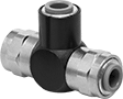 |
Also known as shuttle valves and "or" valves, these valves select between the higher of two inlet pressures to power one outlet port. They're often used in emergency systems where the lower pressure input acts as a backup to the higher pressure input.
Flow Coefficient (Cv)—Flow coefficient (Cv) indicates how much airflow can pass through a valve.
Overall | ||||||||||||||
|---|---|---|---|---|---|---|---|---|---|---|---|---|---|---|
No. of Flow Ports | For Inlet Tube OD | For Outlet Tube OD | Max. Flow Rate @ 100 psi, scfm | Flow Coefficient (Cv) | Pressure Range, psi | Vacuum Rating | Lg. | Wd. | Ht. | Mounting Location | Each | |||
Push-to-Connect Female Inlet x Push-to-Connect Female Outlet | ||||||||||||||
| 3 | 5/32" | 5/32" | 27.12 | 0.48 | 0 to 125 | Not Rated | 1 5/8" | 5/8" | 1 1/8" | Inline | 3084N11 | 000000 | ||
| 3 | 1/4" | 1/4" | 27.12 | 0.48 | 0 to 125 | Not Rated | 1 5/8" | 5/8" | 1 1/8" | Inline | 3084N12 | 00000 | ||
Inline Corrosion-Resistant Air Flow Control Valves
Push-to-Connect Female Inlet × Push-to-Connect Female Outlet
| |  |
Meter Out | Meter In |
Flow Rate @ 73 psi | ||||||||||||
|---|---|---|---|---|---|---|---|---|---|---|---|---|
For Inlet Tube OD | For Outlet Tube OD | Flow Coefficient (Cv) | Min. | Max., scfm | Max. Pressure, psi | Temp. Range, ° F | Flow Adjustment Mechanism | Flow Control Location (ISO Designation) | Each | |||
Polybutylene Body | ||||||||||||
| 1/8" | 1/8" | 0.1 | 0 scfm | 4 | 145 | 32 to 140 | Dial | Exiting Cylinder (Meter Out), Entering Cylinder (Meter In) | 9066K36 | 000000 | ||
| 5/32" | 5/32" | 0.1 | Not Rated | 4 | 145 | 32 to 140 | Dial | Exiting Cylinder (Meter Out), Entering Cylinder (Meter In) | 9066K56 | 00000 | ||
| 5/32" | 5/32" | 0.13 | Not Rated | 5.2 | 145 | 32 to 140 | Dial | Exiting Cylinder (Meter Out), Entering Cylinder (Meter In) | 9066K62 | 00000 | ||
| 3/16" | 3/16" | 0.1 | Not Rated | 4 | 145 | 32 to 140 | Dial | Exiting Cylinder (Meter Out), Entering Cylinder (Meter In) | 9066K58 | 00000 | ||
| 3/16" | 3/16" | 0.29 | Not Rated | 11.6 | 145 | 32 to 140 | Dial | Exiting Cylinder (Meter Out), Entering Cylinder (Meter In) | 9066K65 | 00000 | ||
| 1/4" | 1/4" | 0.1 | Not Rated | 4 | 145 | 32 to 140 | Dial | Exiting Cylinder (Meter Out), Entering Cylinder (Meter In) | 9066K61 | 00000 | ||
| 1/4" | 1/4" | 0.19 | 0 scfm | 9.2 | 145 | 32 to 140 | Dial | Exiting Cylinder (Meter Out), Entering Cylinder (Meter In) | 9066K31 | 00000 | ||
| 1/4" | 1/4" | 0.42 | Not Rated | 16.8 | 145 | 32 to 140 | Dial | Exiting Cylinder (Meter Out), Entering Cylinder (Meter In) | 9066K72 | 00000 | ||
| 1/4" | 1/4" | 0.46 | Not Rated | 18.4 | 145 | 32 to 140 | Dial | Exiting Cylinder (Meter Out), Entering Cylinder (Meter In) | 9066K67 | 00000 | ||
| 5/16" | 5/16" | 0.46 | Not Rated | 18.4 | 145 | 32 to 140 | Dial | Exiting Cylinder (Meter Out), Entering Cylinder (Meter In) | 9066K69 | 00000 | ||
| 5/16" | 5/16" | 0.66 | Not Rated | 26.4 | 145 | 32 to 140 | Dial | Exiting Cylinder (Meter Out), Entering Cylinder (Meter In) | 9066K74 | 00000 | ||
| 3/8" | 3/8" | 0.78 | 0 scfm | 36.8 | 145 | 32 to 140 | Dial | Exiting Cylinder (Meter Out), Entering Cylinder (Meter In) | 9066K32 | 00000 | ||
| 3/8" | 3/8" | 1.05 | Not Rated | 42 | 145 | 32 to 140 | Dial | Exiting Cylinder (Meter Out), Entering Cylinder (Meter In) | 9066K78 | 00000 | ||
| 1/2" | 1/2" | 1.17 | 0 scfm | 55.6 | 145 | 32 to 140 | Dial | Exiting Cylinder (Meter Out), Entering Cylinder (Meter In) | 9066K33 | 00000 | ||
| 3.2 mm | 3.2 mm | 0.1 | Not Rated | 4 | 145 | 32 to 140 | Dial | Exiting Cylinder (Meter Out), Entering Cylinder (Meter In) | 9066K55 | 00000 | ||
| 4 mm | 4 mm | 0.1 | Not Rated | 4 | 145 | 32 to 140 | Dial | Exiting Cylinder (Meter Out), Entering Cylinder (Meter In) | 9066K57 | 00000 | ||
| 4 mm | 4 mm | 0.13 | Not Rated | 5.2 | 145 | 32 to 140 | Dial | Exiting Cylinder (Meter Out), Entering Cylinder (Meter In) | 9066K63 | 00000 | ||
| 6 mm | 6 mm | 0.1 | Not Rated | 4 | 145 | 32 to 140 | Dial | Exiting Cylinder (Meter Out), Entering Cylinder (Meter In) | 9066K59 | 00000 | ||
| 6 mm | 6 mm | 0.23 | Not Rated | 9.2 | 145 | 32 to 140 | Dial | Exiting Cylinder (Meter Out), Entering Cylinder (Meter In) | 9066K64 | 00000 | ||
| 6 mm | 6 mm | 0.29 | Not Rated | 11.6 | 145 | 32 to 140 | Dial | Exiting Cylinder (Meter Out), Entering Cylinder (Meter In) | 9066K66 | 00000 | ||
| 6 mm | 6 mm | 0.42 | Not Rated | 16.8 | 145 | 32 to 140 | Dial | Exiting Cylinder (Meter Out), Entering Cylinder (Meter In) | 9066K71 | 00000 | ||
| 8 mm | 8 mm | 0.46 | Not Rated | 18.4 | 145 | 32 to 140 | Dial | Exiting Cylinder (Meter Out), Entering Cylinder (Meter In) | 9066K68 | 00000 | ||
| 8 mm | 8 mm | 0.66 | Not Rated | 26.4 | 145 | 32 to 140 | Dial | Exiting Cylinder (Meter Out), Entering Cylinder (Meter In) | 9066K73 | 00000 | ||
| 10 mm | 10 mm | 0.92 | Not Rated | 36.8 | 145 | 32 to 140 | Dial | Exiting Cylinder (Meter Out), Entering Cylinder (Meter In) | 9066K75 | 00000 | ||
| 10 mm | 10 mm | 1.05 | Not Rated | 42 | 145 | 32 to 140 | Dial | Exiting Cylinder (Meter Out), Entering Cylinder (Meter In) | 9066K77 | 00000 | ||
| 12 mm | 12 mm | 0.92 | Not Rated | 36.8 | 145 | 32 to 140 | Dial | Exiting Cylinder (Meter Out), Entering Cylinder (Meter In) | 9066K76 | 00000 | ||
| 12 mm | 12 mm | 1.39 | Not Rated | 55.6 | 145 | 32 to 140 | Dial | Exiting Cylinder (Meter Out), Entering Cylinder (Meter In) | 9066K79 | 00000 | ||
Two-Action Electrically Operated Air Directional Control Valves
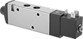 |
Also known as 4-way and 5/2 valves, these valves create two actions, such as extending and then retracting a double-acting cylinder. Apply voltage to the electrical connection to actuate. They direct airflow from the inlet to your equipment and exhaust return airflow to create motion. Return actuation is by spring, so they return to their original position as soon as voltage is removed.
Flow Coefficient (Cv)—Flow coefficient (Cv) indicates how much airflow can pass through a valve.
Overall | |||||||||||||||||||
|---|---|---|---|---|---|---|---|---|---|---|---|---|---|---|---|---|---|---|---|
No. of Flow Ports | Inlet Size | Outlet Size | Exhaust Connection | Max. Flow Rate @ 100 psi, scfm | Flow Coefficient (Cv) | Pressure Range, psi | Vacuum Rating | Lg. | Wd. | Ht. | Mount Type | Mounting Location | Mounting Fasteners Included | Mounting Hole Dia. | Choose a Voltage | Each | |||
Threaded Female Inlet x Threaded Female Outlet | |||||||||||||||||||
Single Solenoid—Spring Return | |||||||||||||||||||
| 4 | 1/4 NPT | 1/4 NPT | Threaded | 45 | 0.75 | 44 to 145 | Not Rated | 5 1/16" | 7/8" | 1 3/8" | Screw In | Inline | No | 0.19" | 12V DC, 24V DC, 120V AC | 62095K8 | 0000000 | ||
Liquid-Dispensing Metering Valves
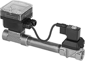 | 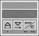 |
Digital Display |
Accurately and consistently dispense a specific amount of liquid—these actuated valves have a screen and buttons for programming batch size and calibration. They’ll automatically shut off once the set amount of liquid has been released. Their stainless steel body resists corrosion, so these valves can be used with harsh chemicals.
Overall | |||||||||||||||||
|---|---|---|---|---|---|---|---|---|---|---|---|---|---|---|---|---|---|
Pipe Size | Gender | Thread Type | Flow Range, gpm | Pipe Schedule | Max. Pressure @ Temp. | Max. Temp., ° F | Max. Current Draw, amp | Valve Lg. | Wd. | Ht. | Enclosure Rating | Certification | For Use With | Each | |||
Stainless Steel Body with Fluoroelastomer Seal | |||||||||||||||||
Fail Closed—120V AC | |||||||||||||||||
| 1/2 | Female | NPT | 2 to 22 | 40 | 145 psi @ 175° F | 140 | 0.06 | 11 1/4" | 3 7/16" | 5 5/8" | IP65 | CSA Certified, UL Recognized Component | Beverage, Food, Boric Acid, Deionized Water, Diesel Fuel, Kerosene, Oil, Sodium Hypochlorite (Bleach), Water | 3738N16 | 000000000 | ||
| 3/4 | Female | NPT | 3 to 38 | 40 | 145 psi @ 175° F | 140 | 0.06 | 12 3/16" | 3 7/16" | 5 3/4" | IP65 | CSA Certified, UL Recognized Component | Beverage, Food, Boric Acid, Deionized Water, Diesel Fuel, Kerosene, Oil, Sodium Hypochlorite (Bleach), Water | 3738N17 | 00000000 | ||
| 1 | Female | NPT | 5 to 62 | 40 | 145 psi @ 175° F | 140 | 0.06 | 12 3/8" | 3 7/16" | 5 7/8" | IP65 | CSA Certified, UL Recognized Component | Beverage, Food, Boric Acid, Deionized Water, Diesel Fuel, Kerosene, Oil, Sodium Hypochlorite (Bleach), Water | 3738N18 | 00000000 | ||
