


Filter by
Product Family
Input Voltage
Electrical Connection
Output Voltage
Voltage
Power
Input Electrical Connection
Wire Connection

Height
Export Control Classification Number (ECCN)
DFARS Specialty Metals
Output Frequency
Width
DC to AC Inverters
Single-Phase Output—Screw-Terminal Input and Plug-In Output
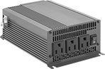 |  | |
With 3 Outlets | With 4 Outlets | NEMA 5-15 Socket |
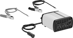
DC to AC Inverters for Sensitive Electronic Loads
Single-Phase Output—Plug-In Input and Plug-In Output
 | |
With Vehicle Input Plug | NEMA 5-15 Socket |
Voltage | Output | |||||||||||||
|---|---|---|---|---|---|---|---|---|---|---|---|---|---|---|
No. of Outlets | Input, V DC | Output, V AC | Power, W | Current, amp | Socket Connection | NEMA Type | Input Plug Connection | Ht. | Wd. | Dp. | Each | |||
Step-Up Voltage | ||||||||||||||
| 1 | 12 | 120 | 125 | 1.1 | 3-Slot Straight | 5-15 | Vehicle | 2.2" | 4.9" | 7.9" | 70555K11 | 0000000 | ||
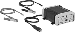
Single-Phase Output—Wire Leads Input and Plug-In Output
 | |
With Wire Leads | NEMA 5-15 Socket |
Voltage | Output | ||||||||||||
|---|---|---|---|---|---|---|---|---|---|---|---|---|---|
No. of Outlets | Input, V DC | Output, V AC | Power, W | Current, amp | Socket Connection | NEMA Type | Ht. | Wd. | Dp. | Each | |||
Step-Up Voltage | |||||||||||||
| 1 | 24 | 120 | 125 | 1.1 | 3-Slot Straight | 5-15 | 2.2" | 4.9" | 7.9" | 70555K17 | 0000000 | ||
Single-Phase Output—Stud-Terminal Input and Plug-In Output
DC to AC Inverter Cords
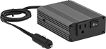 |  |
With One Outlet | With Two Outlets and One USB-A Port |
 | |
With Two Outlets, One USB-A Port, and One USB-C Port | NEMA 5-15 Outlet |
Vehicle Connection | Straight-Blade Connection | USB Connection | Body | Color | ||||||||||||||||
|---|---|---|---|---|---|---|---|---|---|---|---|---|---|---|---|---|---|---|---|---|
Total No. of Outlets | Voltage, V DC | End Shape | NEMA Type | Voltage | Wattage | End Shape | Current | Type (No. of Ports) | End Shape | Lg., ft. | Ht. | Wd. | Dp. | Includes | Body | Cord | Each | |||
| 1 | 12 | Straight | 5-15 | 120V AC | 150 W | Straight | — | — | — | 3 1/2 | 1 3/4" | 3 3/4" | 5 3/4" | — | Red | Black | 6987K35 | 000000 | ||
| 2 | 12 | Straight | 5-15 | 120V AC | 425 W | Straight | 2.1 amp | USB-A (1) | Straight | 2 | 2 5/8" | 5" | 6 1/2" | Battery Cable with Alligator Clips | Yellow/White | Yellow | 6987K36 | 00000 | ||
| 2 | 12 | Straight | 5-15 | 120V AC | 400 W | Straight | 2.4 amp 3 amp | USB-A (1) USB-C (1) | Straight | 3 | 2 1/2" | 5 3/4" | 7" | Battery Cable with Alligator Clips | Black/Yellow | Black | 6987K24 | 00000 | ||
DC to AC Inverters for Motor Loads
Single-Phase Output—Plug-In Input and Plug-In Output
 | |
With Vehicle Input Plug | NEMA 5-15 Socket |
Voltage | Output | |||||||||||||
|---|---|---|---|---|---|---|---|---|---|---|---|---|---|---|
No. of Outlets | Input, V DC | Output, V AC | Power, W | Current, amp | Socket Connection | NEMA Type | Input Plug Connection | Ht. | Wd. | Dp. | Each | |||
Step-Up Voltage | ||||||||||||||
| 4 | 11 to 15 | 120 | 375 | 1 | 3-Slot Straight | 5-15 | Vehicle | 2.4" | 4.2" | 6" | 76815K86 | 000000 | ||
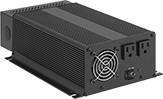
Single-Phase Output—Screw-Terminal Input and Plug-In Output
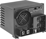 | |
With Screw Terminals | NEMA 5-15 Socket |
Voltage | Output | ||||||||||||
|---|---|---|---|---|---|---|---|---|---|---|---|---|---|
No. of Outlets | Input, V DC | Output, V AC | Power, W | Current, amp | Socket Connection | NEMA Type | Ht. | Wd. | Dp. | Each | |||
Step-Up Voltage | |||||||||||||
| 2 | 12 | 120 | 1,250 | 10.4 | 3-Slot Straight | 5-15 | 7" | 8.8" | 9" | 6987K91 | 0000000 | ||
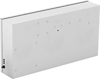
Backup Power Supplies for Facility Lights
Backup Power Supplies
 |
Overall | Mounting Holes | Housing | ||||||||||||||||||
|---|---|---|---|---|---|---|---|---|---|---|---|---|---|---|---|---|---|---|---|---|
Wattage, W | Max. Recommended Power, W | Input Voltage, V AC | Output Voltage, V AC | Lg. | Ht. | Wd. | Battery Test Type | Trip Time, sec. | For Conduit Trade Size | Mounting Hardware Included | No. of | Dia. | Material | Color | Temp., ° F | Specifications Met | Cannot Be Sold To | Each | ||
| 35 | 35 | 120 to 277 | 120, 277 | 19 7/8" | 2 3/4" | 2 7/8" | Manual | 5 | — | No | 4 | 5/32" | Steel | Gray | 32 to 120 | NFPA 70 NFPA 101 7.8.1.2.2 UL 924 UL Listed C-UL Listed | — | 8197N26 | 0000000 | |
| 50 | 50 | 120 to 277 | 120, 277 | 22 1/2" | 2 3/4" | 3" | Manual | 5 | — | No | 4 | 5/32" | Steel | Gray | 32 to 120 | NFPA 70 NFPA 101 7.8.1.2.2 UL 924 UL Listed C-UL Listed | — | 8197N21 | 000000 | |
| 125 | 125 | 120 to 277 | 120, 277 | 23 1/8" | 11 3/4" | 4 1/2" | Manual | 0.05 | 1/2 | No | 2 | 1/2" | Steel | White | 70 to 85 | NFPA 70 NFPA 101 7.8.1.2.2 UL 924 UL Listed | Canada | 8197N125 | 000000 | |
| 125 | 125 | 120 to 277 | 120, 277 | 23 1/8" | 11 3/4" | 4 1/2" | Manual | 0.05 | 1/2 | No | 2 | 1/2" | Steel | White | 70 to 85 | NFPA 70 NFPA 101 7.8.1.2.2 UL 924 UL Listed C-UL Listed | California | 8197N122 | 000000 | |
| 250 | 250 | 120 to 277 | 120, 277 | 19 1/8" | 11 5/8" | 7 5/8" | Manual | 1 | 1/2 | No | 2 | 1/2" | Steel | White | 70 to 85 | NFPA 70 NFPA 101 7.8.1.2.2 UL 924 UL Listed C-UL Listed | — | 8197N126 | 00000000 | |
| 375 | 337 | 120 to 277 | 120, 277 | 23" | 17 3/4" | 8 1/4" | Manual | 1 | 1/2 | No | 2 | 1/2" | Steel | White | 70 to 85 | NFPA 70 NFPA 101 7.8.1.2.2 UL 924 UL Listed | California, Canada | 8197N123 | 00000000 | |
| 550 | 495 | 120 to 277 | 120, 277 | 23" | 17 3/4" | 8 1/4" | Manual | 1 | 1/2 | No | 2 | 1/2" | Steel | White | 70 to 85 | NFPA 70 NFPA 101 7.8.1.2.2 UL 924 UL Listed | California, Canada | 8197N124 | 00000000 | |
| 550 | 550 | 120 to 277 | 120, 277 | 19 3/4" | 22" | 11" | Manual | 1 | 1/2 | No | 2 | 1/2" | Steel | White | 70 to 85 | NFPA 70 NFPA 101 7.8.1.2.2 UL 924 UL Listed | Canada | 8197N127 | 00000000 | |
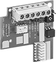
Relays
 |  |
Unthreaded Through-Hole Mount | Fastener Mount |
Relays have an LED indicator that tells you if your lights are using primary or backup power and when these relays require maintenance. They also have a test switch to make sure the system is working.
Unthreaded Through-Hole Mount—Relays that mount into an unthreaded through hole install into knockouts in junction boxes and light fixtures.
Fastener Mount—Fastener-mount relays are ideal when space is tight or you want to hide your relay. They fit inside a ballast channel to keep everything contained within your fixture housing.
Current | Overall | Mounting Holes | Wire Lead | Conduit Connection | |||||||||||||||||||||
|---|---|---|---|---|---|---|---|---|---|---|---|---|---|---|---|---|---|---|---|---|---|---|---|---|---|
Input Voltage, V AC | Output Voltage, V AC | Control, mA | Switching, amp | Max. Switching Voltage, V AC | Mechanical Life Cycles | Trip Time, sec. | Ht. | Wd. | Dp. | Battery Test Type | Mounting Fasteners Included | No. of | Dia. | Lg. | No. of | Gender | Trade Size | Thread Type | Temp., ° F | Enclosure Rating | Specifications Met | Each | |||
1 Circuit Controlled with 1 Off (Normally Open)—SPST-NO | |||||||||||||||||||||||||
Unthreaded Through-Hole Mount | |||||||||||||||||||||||||
| 120 to 277 | 120 to 277 | 118 | 20 | 277 | 10,000,000 | 0.018 | 4" | 4" | 1 3/4" | Manual | Yes | 4 | 0.19" | 16" | 6 | Male | 1/2 | NPT | -30 to 140 | NEMA 1 | NFPA 101 7.8.1.2.2 UL 924 UL Listed C-UL Listed CE Marked | 8197N12 | 0000000 | ||
Fastener Mount | |||||||||||||||||||||||||
| 120 to 277 | 120 to 277 | 118 | 10 | 277 | 10,000,000 | 0.018 | 1 3/4" | 4 3/4" | 1 1/4" | Manual | No | 2 | 0.19" | 16" | 10 | — | — | — | -30 to 140 | NEMA 1 | NFPA 101 7.8.1.2.2 UL 924 UL Listed C-UL Listed CE Marked | 8197N13 | 000000 | ||
 |
Add a remote testing button to test relays behind the wall or ceiling. Install it directly onto the ceiling or into a standard 4" × 4" round or octagonal junction box.
Overall Dia. | Material | Color | Wire Connection | Mounting Fasteners Included | Specs. Met | Certification | Each | ||
|---|---|---|---|---|---|---|---|---|---|
| 4" | Plastic | White | Screw Terminal | Yes | UL 924 | C-UL Listed, CE Marked, UL Listed | 8197N11 | 000000 |
DIN-Rail Mount VFDs
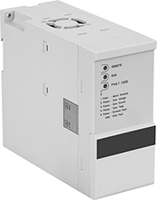 |
Mount these VFDs to DIN rail inside a control panel. Set them to automatically adjust motor speed. Wire a potentiometer (not included) for remote manual control.
Output | |||||||||
|---|---|---|---|---|---|---|---|---|---|
For Max. Motor Power, hp | Max. Current, amp | Nominal Voltage | Frequency, Hz | Input Analog Signal | Mounting Location | Each | |||
Single Phase—120V AC Nominal Input Voltage | |||||||||
| 1/2 | 3 | 115V AC | 0 to 400 | 4 mA to 20 mA, 0V DC to 10V DC | DIN Rail, Panel | 7786K651 | 0000000 | ||
| 1 | 4.8 | 115V AC | 0 to 400 | 4 mA to 20 mA, 0V DC to 10V DC | DIN Rail, Panel | 7786K652 | 000000 | ||
Single Phase—240V AC Nominal Input Voltage | |||||||||
| 1 | 4.8 | 230V AC | 0 to 400 | 4 mA to 20 mA, 0V DC to 10V DC | DIN Rail, Panel | 7786K658 | 000000 | ||
| 2 | 7.8 | 230V AC | 0 to 400 | 4 mA to 20 mA, 0V DC to 10V DC | DIN Rail, Panel | 7786K655 | 000000 | ||
| 3 | 11 | 230V AC | 0 to 400 | 4 mA to 20 mA, 0V DC to 10V DC | DIN Rail, Panel | 7786K656 | 000000 | ||
Three Phase—240V AC Nominal Input Voltage | |||||||||
| 1 | 4.8 | 230V AC | 0 to 400 | 4 mA to 20 mA, 0V DC to 10V DC | DIN Rail, Panel | 7786K657 | 000000 | ||
| 2 | 7.8 | 230V AC | 0 to 400 | 4 mA to 20 mA, 0V DC to 10V DC | DIN Rail, Panel | 7786K659 | 000000 | ||
| 3 | 11 | 230V AC | 0 to 400 | 4 mA to 20 mA, 0V DC to 10V DC | DIN Rail, Panel | 7786K761 | 000000 | ||
Three Phase—480V AC Nominal Input Voltage | |||||||||
| 1 | 2.2 | 460V AC | 0 to 400 | 4 mA to 20 mA, 0V DC to 10V DC | DIN Rail, Panel | 7786K762 | 000000 | ||
| 3 | 5.6 | 460V AC | 0 to 400 | 4 mA to 20 mA, 0V DC to 10V DC | DIN Rail, Panel | 7786K763 | 000000 | ||
| 5 | 7.6 | 460V AC | 0 to 400 | 4 mA to 20 mA, 0V DC to 10V DC | DIN Rail, Panel | 7786K764 | 000000 | ||
| 7 1/2 | 12 | 460V AC | 0 to 400 | 4 mA to 20 mA, 0V DC to 10V DC | DIN Rail, Panel | 7786K765 | 00000000 | ||
Sensor Signal Adapter Cords
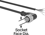 | |
5-Pole A Code |
Send data between sensors and receivers that have different signal types. These cords change the output signal from PNP to NPN. They connect your sensor to equipment with an M12 connection. Since they’re A coded, these cords work with most AC and DC systems. They’re also used to connect sensors to IO Link controllers and within fieldbus systems, such as Profibus and DeviceNet.
These cords were designed with tough industrial applications in mind. Insulated with polyurethane, they bend easily without cracking, and they won’t break down from oil or coolants. They’re IP rated to block out water if briefly submerged or sprayed during high-pressure washdowns. With a 90° elbow socket, these cords sit flush against equipment, so they fit behind machinery and in other tight spaces. The socket has internal threads that keep it from shaking loose due to vibration.
To determine the signal output of your sensor, use a tester (not included).
Digital Signal | Socket | Cord | |||||||||||||||||
|---|---|---|---|---|---|---|---|---|---|---|---|---|---|---|---|---|---|---|---|
Switch Starting Position | No. of Poles | Input | Output | Housing Thread Size | Face Dia. | Lg., ft. | Current, amp | Voltage, V DC | AWG | OD | Insulation Material | Temp. Range, ° F | Enclosure Rating | Certification | Color | Each | |||
90° Elbow Socket (Internal Thread) × Wire Leads | |||||||||||||||||||
A-Coded—Unshielded | |||||||||||||||||||
| 1 Off | 5 | PNP | NPN | M12 × 1 mm | 0.3" | 16 | 0.1 | 24 | 22 | 0.43" | Polyurethane Rubber | -10 to 140 | IP65, IP68, IP69K | CE Marked | Black | 5462N11 | 000000 | ||
| 1 On | 5 | PNP | NPN | M12 × 1 mm | 0.3" | 16 | 0.1 | 24 | 22 | 0.43" | Polyurethane Rubber | -10 to 140 | IP65, IP68, IP69K | CE Marked | Black | 5462N12 | 00000 | ||
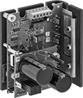
Open-Frame DC Motor Drives
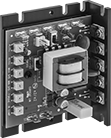 |
Without an enclosure, these drives are ready to build directly into a machine. Adjust the dial to manually control the speed and torque of your setup’s DC motor, or hook them up to your PLC to automate control. These drives have potentiometers to set parameters, such as minimum and maximum speed.
Drives | Heat Sinks | |||||||||||
|---|---|---|---|---|---|---|---|---|---|---|---|---|
Output | Input | |||||||||||
Max. Current without Heat Sink, amp | Max. Current with Heat Sink, amp | Voltage, V DC | For Motor Power @ Voltage | Nominal Voltage | Electrical Phase | Certification | Each | Each | ||||
DC-to-DC | ||||||||||||
Nonreversing Motor | ||||||||||||
| 16 | — | 0 to 12 0 to 24 | 1/6 hp @ 12V DC 1/6 hp to 1/3 hp @ 24V DC | 12V DC/24V DC | — | C-UL Listed | 7729K13 | 0000000 | ——— | 0 | ||
| 60 | — | 0 to 12 0 to 24 | 3/4 hp @ 12V DC 3/4 hp to 1 hp @ 24V DC | 12V DC/24V DC | — | C-UL Listed | 7729K11 | 000000 | ——— | 0 | ||
AC-to-DC | ||||||||||||
Nonreversing Motor | ||||||||||||
| 5 | 10 | 0 to 90 0 to 180 | 1/8 hp to 1 hp @ 90V DC 1/4 hp to 2 hp @ 180V DC | 120V AC/240V AC | Single | C-UL Listed, UL Listed | 7793K12 | 000000 | 7793K65 | 000000 | ||
DC Motor Drives
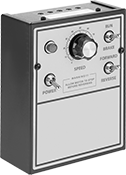 |
Control the speed and torque of DC motors. These drives have a dial for manual adjustments, or you can automate control by hooking them up to your PLC. Use the potentiometers to set parameters, such as minimum and maximum speed.
Reversing Motor—Operate in either direction with the flip of a switch or an input from your PLC. There’s no need to rewire the drive.
Drives | Heat Sinks | |||||||||||
|---|---|---|---|---|---|---|---|---|---|---|---|---|
Output | Input | |||||||||||
Max. Current without Heat Sink, amp | Max. Current with Heat Sink, amp | Voltage, V DC | For Motor Power @ Voltage | Nominal Voltage | Electrical Phase | Certification | Each | Each | ||||
AC-to-DC | ||||||||||||
Nonreversing Motor | ||||||||||||
| 5 | 10 | 0 to 90 0 to 180 | 1/8 hp to 1 hp @ 90V DC 1/4 hp to 2 hp @ 180V DC | 120V AC/240V AC | Single | C-UL Listed, UL Listed | 7793K51 | 0000000 | 7793K55 | 0000000 | ||
Reversing Motor | ||||||||||||
| 5 | 10 | 0 to 90 0 to 180 | 1/8 hp to 1 hp @ 90V DC 1/4 hp to 2 hp @ 180V DC | 120V AC/240V AC | Single | C-UL Listed, UL Listed | 7793K52 | 000000 | 7793K55 | 000000 | ||
Stepper Motor Drives
 |
Overall | ||||||||||||
|---|---|---|---|---|---|---|---|---|---|---|---|---|
Current per Phase, amp | Voltage | Step Resolution | No. of Step Resolution Settings | Max. Step Freq., MHz | For Stepper Motor Polarity | Wire Connection | Lg. | Wd. | Ht. | Each | ||
| 0.3 to 2.2 | 12V DC to 48V DC | 1, 1/2, 1/10, 1/25, 1/64, 1/100 | 6 | 2 | Bipolar | Screw Terminal | 2.6" | 3.7" | 0.8" | 6627T911 | 0000000 | |
| 2.35 to 8 | 24V DC to 75V DC | 1, 1/2, 1/10, 1/25, 1/64, 1/100 | 6 | 2 | Bipolar | Screw Terminal | 3.3" | 4.7" | 1.3" | 6627T912 | 000000 | |
| 0.4 to 8 | 90V AC to 240V AC | 1, 1/2, 1/4, 1/5, 1/8, 1/10, 1/16, 1/20, 1/25, 1/32, 1/40, 1/50, 1/64, 1/100, 1/125, 1/128 | 16 | 2 | Bipolar | Screw Terminal | 4.7" | 7" | 2.1" | 6627T914 | 000000 | |
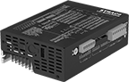
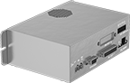
Washdown DC Motor Drives
 |
Keep these drives dry, even near washdown zones. A NEMA 4X-rated enclosure seals out moisture and dust. Adjust the dial to manually control the speed and torque of your setup’s DC motor, or hook them up to your PLC to automate control. These drives have potentiometers to set parameters, such as minimum and maximum speed.
Reversing Motor—Operate in either direction with the flip of a switch or an input from your PLC. There’s no need to rewire the drive.
Output | Input | |||||||||
|---|---|---|---|---|---|---|---|---|---|---|
Max. Current, amp | Voltage, V DC | For Motor Power @ Voltage | Nominal Voltage | Electrical Phase | Enclosure Rating | Certification | Each | |||
AC-to-DC | ||||||||||
Nonreversing Motor | ||||||||||
| 10 | 0 to 90 0 to 180 | 1/8 hp to 1 hp @ 90V DC 1/4 hp to 2 hp @ 180V DC | 120V AC/240V AC | Single | NEMA 4X | C-UL Listed, UL Listed | 7793K63 | 0000000 | ||
Reversing Motor | ||||||||||
| 10 | 0 to 90 0 to 180 | 1/8 hp to 1 hp @ 90V DC 1/4 hp to 2 hp @ 180V DC | 120V AC/240V AC | Single | NEMA 4X | C-UL Listed, UL Listed | 7793K64 | 000000 | ||
Stepper Motor Controller/Drives
 |
No. of Inputs/Outputs | Overall | ||||||||||||||
|---|---|---|---|---|---|---|---|---|---|---|---|---|---|---|---|
Current per Phase, amp | Voltage | Step Resolution | No. of Step Resolution Settings | Max. Step Freq., MHz | Digital (Input) | Digital (Output) | For Stepper Motor Polarity | Lg. | Wd. | Ht. | Includes | Features | Each | ||
| 0.1 to 6 | 12V DC to 48V DC | 1 to 1/256 | 25,501 | 2 | 8 | 4 | Bipolar | 2.4" | 3.9" | 0.9" | I/O Cable | — | 6627T93 | 0000000 | |
| 0.1 to 10 | 24V DC to 80V DC | 1 to 1/256 | 25,501 | 2 | 8 | 4 | Bipolar | 3" | 5" | 1.75" | — | Encoder Compatible | 6627T916 | 000000 | |
| 0.5 to 6 | 94V AC to 135V AC | 1 to 1/256 | 25,501 | 2 | 7 | 3 | Bipolar | 4.7" | 6.4" | 2.3" | — | — | 6627T917 | 00000000 | |
Open Frame VFDs
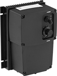
Washdown VFDs
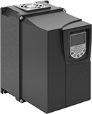 |
Rated NEMA 4, these VFDs are protected from washdowns. Set them to automatically adjust motor speed. Wire a potentiometer (not included) for remote manual control.
NEMA 12 Enclosure Rating—Controls rated NEMA 12 also protect against splashes of oil and coolant when used indoors only.
Output | ||||||||||
|---|---|---|---|---|---|---|---|---|---|---|
For Max. Motor Power, hp | Max. Current, amp | Nominal Voltage | Frequency, Hz | Input Analog Signal | Environment | Enclosure Rating | Each | |||
Single Phase—240V AC Nominal Input Voltage | ||||||||||
| 1 1/2 | 4.3 | 230V AC | 0 to 120 | 4 mA to 20 mA, 0V DC to 10V DC | Oily, Outdoor, Washdown, Wet, Corrosive, Dusty | NEMA 4, NEMA 12, IP66 | 7786K721 | 0000000 | ||
Single/Three Phase—240V AC Nominal Input Voltage | ||||||||||
| 2 | 7.3 | 230V AC | 0 to 500 | 4 mA to 20 mA, 0V DC to 10V DC | Outdoor, Washdown, Wet, Dusty | NEMA 4, IP66 | 7786K391 | 000000 | ||
Three Phase—480V AC Nominal Input Voltage | ||||||||||
| 3 | 4.3 | 460V AC | 0 to 500 | 4 mA to 20 mA, 0V DC to 10V DC | Outdoor, Washdown, Wet, Dusty | NEMA 4, IP66 | 7786K361 | 00000000 | ||
| 3 | 4.3 | 460V AC | 0 to 500 | 4 mA to 20 mA, 0V DC to 10V DC | Outdoor, Washdown, Wet, Corrosive, Dusty | NEMA 4, IP66 | 7786K381 | 00000000 | ||
