


Filter by
Pipe Material
Fitting Type


Fitting Connection


Length
Maximum Pressure @ Temperature
Nut Material
DFARS Specialty Metals
ID
Maximum Temperature
Minimum Temperature

About Pipe and Fittings
Measure your pipe and fittings to identify their pipe size, thread size, schedule, and thread type. Then, find compatible components.
Low-Pressure Iron and Steel Threaded Pipe Fittings
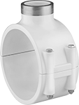
Saddle Tap Tees with Gasket
 |
Female × Clamp On |
Saddle tap tees tap into existing pipe lines so you can install branch lines, valves, and other equipment. The gasket and clamps create a tight seal so the opening won’t leak. To install, shut down your line and secure the clamps, then drill a hole into the pipe.
Pipe Size (A) | For Pipe Size (B) | For Pipe OD (B) | Material | Color | Max. Pressure @ Temp. | Gasket Material | Clamp Material | Each | |||
|---|---|---|---|---|---|---|---|---|---|---|---|
NPT Female × Clamp On | |||||||||||
| 1/2 | 1 1/2, 1 1/4 | 1.66", 1.9" | Epoxy-Coated Iron | Blue | 100 psi @ 72° F | Buna-N | Galvanized Steel | 4572K211 | 000000 | ||
| 1/2 | 2 | 2 3/8" | Epoxy-Coated Iron | Blue | 100 psi @ 72° F | Buna-N | Galvanized Steel | 4572K212 | 00000 | ||
| 1/2 | 3 | 3 1/2" | Epoxy-Coated Iron | Blue | 100 psi @ 72° F | Buna-N | Galvanized Steel | 4572K213 | 00000 | ||
| 1/2 | 4 | 4 1/2" | Epoxy-Coated Iron | Blue | 100 psi @ 72° F | Buna-N | Galvanized Steel | 4572K214 | 00000 | ||
| 1/2 | 6 | 6 5/8" | Epoxy-Coated Iron | Blue | 100 psi @ 72° F | Buna-N | Galvanized Steel | 4572K215 | 00000 | ||
| 1/2 | 8 | 8 5/8" | Epoxy-Coated Iron | Blue | 100 psi @ 72° F | Buna-N | Galvanized Steel | 4572K216 | 00000 | ||
| 3/4 | 1 1/2, 1 1/4 | 1.66", 1.9" | Epoxy-Coated Iron | Blue | 100 psi @ 72° F | Buna-N | Galvanized Steel | 4572K221 | 00000 | ||
| 3/4 | 2 | 2 3/8" | Epoxy-Coated Iron | Blue | 100 psi @ 72° F | Buna-N | Galvanized Steel | 4572K222 | 00000 | ||
| 3/4 | 3 | 3 1/2" | Epoxy-Coated Iron | Blue | 100 psi @ 72° F | Buna-N | Galvanized Steel | 4572K223 | 00000 | ||
| 3/4 | 4 | 4 1/2" | Epoxy-Coated Iron | Blue | 100 psi @ 72° F | Buna-N | Galvanized Steel | 4572K224 | 00000 | ||
| 3/4 | 6 | 6 5/8" | Epoxy-Coated Iron | Blue | 100 psi @ 72° F | Buna-N | Galvanized Steel | 4572K225 | 00000 | ||
| 3/4 | 8 | 8 5/8" | Epoxy-Coated Iron | Blue | 100 psi @ 72° F | Buna-N | Galvanized Steel | 4572K226 | 00000 | ||
| 1 | 1 1/2, 1 1/4 | 1.66", 1.9" | Epoxy-Coated Iron | Blue | 100 psi @ 72° F | Buna-N | Galvanized Steel | 4572K231 | 00000 | ||
| 1 | 2 | 2 3/8" | Epoxy-Coated Iron | Blue | 100 psi @ 72° F | Buna-N | Galvanized Steel | 4572K232 | 00000 | ||
| 1 | 3 | 3 1/2" | Epoxy-Coated Iron | Blue | 100 psi @ 72° F | Buna-N | Galvanized Steel | 4572K233 | 00000 | ||
| 1 | 4 | 4 1/2" | Epoxy-Coated Iron | Blue | 100 psi @ 72° F | Buna-N | Galvanized Steel | 4572K234 | 00000 | ||
| 1 | 6 | 6 5/8" | Epoxy-Coated Iron | Blue | 100 psi @ 72° F | Buna-N | Galvanized Steel | 4572K235 | 00000 | ||
| 1 | 8 | 8 5/8" | Epoxy-Coated Iron | Blue | 100 psi @ 72° F | Buna-N | Galvanized Steel | 4572K236 | 00000 | ||
| 1 1/4 | 2 | 2 3/8" | Epoxy-Coated Iron | Blue | 100 psi @ 72° F | Buna-N | Galvanized Steel | 4572K241 | 00000 | ||
| 1 1/4 | 3 | 3 1/2" | Epoxy-Coated Iron | Blue | 100 psi @ 72° F | Buna-N | Galvanized Steel | 4572K242 | 00000 | ||
| 1 1/4 | 4 | 4 1/2" | Epoxy-Coated Iron | Blue | 100 psi @ 72° F | Buna-N | Galvanized Steel | 4572K243 | 00000 | ||
| 1 1/4 | 6 | 6 5/8" | Epoxy-Coated Iron | Blue | 100 psi @ 72° F | Buna-N | Galvanized Steel | 4572K244 | 000000 | ||
| 1 1/4 | 8 | 8 5/8" | Epoxy-Coated Iron | Blue | 100 psi @ 72° F | Buna-N | Galvanized Steel | 4572K245 | 000000 | ||
| 1 1/2 | 2 | 2 3/8" | Epoxy-Coated Iron | Blue | 100 psi @ 72° F | Buna-N | Galvanized Steel | 4572K251 | 00000 | ||
| 1 1/2 | 3 | 3 1/2" | Epoxy-Coated Iron | Blue | 100 psi @ 72° F | Buna-N | Galvanized Steel | 4572K252 | 00000 | ||
| 1 1/2 | 4 | 4 1/2" | Epoxy-Coated Iron | Blue | 100 psi @ 72° F | Buna-N | Galvanized Steel | 4572K253 | 00000 | ||
| 1 1/2 | 6 | 6 5/8" | Epoxy-Coated Iron | Blue | 100 psi @ 72° F | Buna-N | Galvanized Steel | 4572K254 | 000000 | ||
| 1 1/2 | 8 | 8 5/8" | Epoxy-Coated Iron | Blue | 100 psi @ 72° F | Buna-N | Galvanized Steel | 4572K255 | 000000 | ||
| 2 | 3 | 3 1/2" | Epoxy-Coated Iron | Blue | 100 psi @ 72° F | Buna-N | Galvanized Steel | 4572K261 | 00000 | ||
| 2 | 4 | 4 1/2" | Epoxy-Coated Iron | Blue | 100 psi @ 72° F | Buna-N | Galvanized Steel | 4572K262 | 00000 | ||
| 2 | 6 | 6 5/8" | Epoxy-Coated Iron | Blue | 100 psi @ 72° F | Buna-N | Galvanized Steel | 4572K263 | 000000 | ||
| 2 | 8 | 8 5/8" | Epoxy-Coated Iron | Blue | 100 psi @ 72° F | Buna-N | Galvanized Steel | 4572K264 | 000000 | ||
180° Bend Connectors
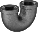 |
180° bend connectors are also known as U-bends.
Pipe Size | Material | Max. Pressure @ Temp. | Max. Steam Pressure @ Temp. | Certification | Shape | Each | |||
|---|---|---|---|---|---|---|---|---|---|
NPT Female | |||||||||
| 1/2 | Iron | 150 psi @ 72° F | 150 psi @ 350° F | UL Listed | 180° Bend | 44605K563 | 000000 | ||
| 3/4 | Iron | 150 psi @ 72° F | 150 psi @ 350° F | UL Listed | 180° Bend | 44605K564 | 00000 | ||
| 1 | Iron | 150 psi @ 72° F | 150 psi @ 350° F | — | 180° Bend | 44605K565 | 00000 | ||
| 1 1/4 | Iron | 150 psi @ 72° F | 150 psi @ 350° F | UL Listed | 180° Bend | 44605K566 | 00000 | ||
| 1 1/2 | Iron | 150 psi @ 72° F | 150 psi @ 350° F | UL Listed | 180° Bend | 44605K567 | 000000 | ||
| 2 | Iron | 150 psi @ 72° F | 150 psi @ 350° F | UL Listed | 180° Bend | 44605K568 | 000000 | ||
Thick-Wall Plastic Pipe Fittings for Water
Saddle Tap Tees with Collar and Gasket
 |
Female x Clamp On |
Saddle-tap tee adapters allow you to create additional outlets and connections in metal or plastic pipe. To install, shut down your line and drill a hole in the pipe where you want to create a connection. Position the saddle over the hole so the gasket and lip are fully engaged and secure with the included nuts, bolts, and washers.
Fittings with collar have a stainless steel reinforcement on the female threads to prevent the threads from cracking.
NSF/ANSI 61—To adhere to safety standards for drinking water systems, use pipe that meets NSF/ANSI 61.
Pipe Size (A) | For Pipe Size (B) | For Pipe OD (B) | For Hole Dia. | Pipe Schedule | Material | Color | Max. Pressure @ Temp. | Gasket Material | Food Industry Std. | Each | |||
|---|---|---|---|---|---|---|---|---|---|---|---|---|---|
NPT Female × Clamp On | |||||||||||||
| 1/2 | 2 | 2 3/8" | 3/4" | 80 | PVC | Dark Gray | 200 psi @ 72° F | EPDM | NSF/ANSI 61 | 4849K51 | 000000 | ||
| 1/2 | 3 | 3 1/2" | 7/8" | 80 | PVC | Dark Gray | 200 psi @ 72° F | EPDM | NSF/ANSI 61 | 4849K56 | 00000 | ||
| 1/2 | 4 | 4 1/2" | 1 1/8" | 80 | PVC | Dark Gray | 200 psi @ 72° F | EPDM | NSF/ANSI 61 | 4849K63 | 000000 | ||
| 3/4 | 2 | 2 3/8" | 7/8" | 80 | PVC | Dark Gray | 200 psi @ 72° F | EPDM | NSF/ANSI 61 | 4849K52 | 00000 | ||
| 3/4 | 3 | 3 1/2" | 7/8" | 80 | PVC | Dark Gray | 200 psi @ 72° F | EPDM | NSF/ANSI 61 | 4849K57 | 00000 | ||
| 3/4 | 4 | 4 1/2" | 1 1/8" | 80 | PVC | Dark Gray | 200 psi @ 72° F | EPDM | NSF/ANSI 61 | 4849K64 | 000000 | ||
| 1 | 2 | 2 3/8" | 1 1/8" | 80 | PVC | Dark Gray | 200 psi @ 72° F | EPDM | NSF/ANSI 61 | 4849K53 | 00000 | ||
| 1 | 3 | 3 1/2" | 1 1/8" | 80 | PVC | Dark Gray | 200 psi @ 72° F | EPDM | NSF/ANSI 61 | 4849K58 | 00000 | ||
| 1 | 4 | 4 1/2" | 1 1/8" | 80 | PVC | Dark Gray | 200 psi @ 72° F | EPDM | NSF/ANSI 61 | 4849K65 | 000000 | ||
| 1 | 6 | 6 5/8" | 1 1/8" | 80 | PVC | Dark Gray | 315 psi @ 72° F | EPDM | NSF/ANSI 61 | 4849K74 | 000000 | ||
| 1 1/2 | 3 | 3 1/2" | 2 1/4" | 80 | PVC | Dark Gray | 200 psi @ 72° F | EPDM | NSF/ANSI 61 | 4849K61 | 00000 | ||
| 1 1/2 | 4 | 4 1/2" | 1 3/4" | 80 | PVC | Dark Gray | 200 psi @ 72° F | EPDM | NSF/ANSI 61 | 4849K67 | 000000 | ||
| 2 | 3 | 3 1/2" | 2 1/4" | 80 | PVC | Dark Gray | 200 psi @ 72° F | EPDM | NSF/ANSI 61 | 4849K62 | 00000 | ||
| 2 | 4 | 4 1/2" | 2 1/4" | 80 | PVC | Dark Gray | 200 psi @ 72° F | EPDM | NSF/ANSI 61 | 4849K68 | 000000 | ||
| 2 | 6 | 6 5/8" | 2 1/4" | 80 | PVC | Dark Gray | 200 psi @ 72° F | EPDM | NSF/ANSI 61 | 4849K82 | 000000 | ||
| 3 | 4 | 4 1/2" | 3" | 80 | PVC | Dark Gray | 185 psi @ 72° F | EPDM | NSF/ANSI 61 | 4849K71 | 000000 | ||
| 3 | 6 | 6 5/8" | 3" | 80 | PVC | Dark Gray | 185 psi @ 72° F | EPDM | NSF/ANSI 61 | 4849K83 | 000000 | ||
Standard-Wall Plastic Pipe Fittings for Water
Saddle Tap Tees with Gasket
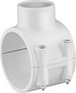 |
Female × Clamp On |
Saddle-tap tee adapters allow you to create additional outlets and connections in metal or plastic pipe. To install, shut down your line and drill a hole in the pipe where you want to create a connection. Position the saddle over the hole so the gasket and lip are fully engaged and secure with the included nuts, bolts, and washers.
Cement-Socket Fitting Connection—Attach socket-connect ends to unthreaded pipe or another socket-connect fitting with a PVC primer and cement (also known as solvent weld).
NSF/ANSI 61—To adhere to safety standards for drinking water systems, use pipe that meets NSF/ANSI 61.
Pipe Size (A) | For Pipe Size (B) | For Pipe OD (B) | For Hole Dia. | OD | Pipe Schedule | Material | Color | Max. Pressure @ Temp. | Gasket Material | Food Industry Std. | Each | |||
|---|---|---|---|---|---|---|---|---|---|---|---|---|---|---|
Cement Socket Female × Clamp On | ||||||||||||||
| 1 1/2 | 3 | 3 1/2" | 2 1/4" | 1 29/32" | 40 | PVC | White | 200 psi @ 72° F | EPDM | NSF/ANSI 61 | 4763K21 | 000000 | ||
| 1 1/2 | 4 | 4 1/2" | 1 3/4" | 1 29/32" | 40 | PVC | White | 200 psi @ 72° F | EPDM | NSF/ANSI 61 | 4763K27 | 000000 | ||
| 2 | 3 | 3 1/2" | 2 1/4" | 2 3/8" | 40 | PVC | White | 200 psi @ 72° F | EPDM | NSF/ANSI 61 | 4763K22 | 00000 | ||
| 2 | 4 | 4 1/2" | 2 1/4" | 2 3/8" | 40 | PVC | White | 200 psi @ 72° F | EPDM | NSF/ANSI 61 | 4763K28 | 000000 | ||
| 2 | 6 | 6 5/8" | 2 1/4" | 2 3/8" | 40 | PVC | White | 200 psi @ 72° F | EPDM | NSF/ANSI 61 | 4763K82 | 000000 | ||
| 3 | 4 | 4 1/2" | 3" | 3 1/2" | 40 | PVC | White | 200 psi @ 72° F | EPDM | NSF/ANSI 61 | 4763K31 | 000000 | ||
Saddle Tap Tees with Collar and Gasket
 |
Female × Clamp On |
Saddle-tap tee adapters allow you to create additional outlets and connections in metal or plastic pipe. To install, shut down your line and drill a hole in the pipe where you want to create a connection. Position the saddle over the hole so the gasket and lip are fully engaged and secure with the included nuts, bolts, and washers.
Fittings with collar have a stainless steel reinforcement on the female threads to prevent the threads from cracking.
NSF/ANSI 61—To adhere to safety standards for drinking water systems, use pipe that meets NSF/ANSI 61.
Pipe Size (A) | For Pipe Size (B) | For Pipe OD (B) | For Hole Dia. | OD | Pipe Schedule | Material | Color | Max. Pressure @ Temp. | Gasket Material | Food Industry Std. | Each | |||
|---|---|---|---|---|---|---|---|---|---|---|---|---|---|---|
NPT Female × Clamp On | ||||||||||||||
| 1/2 | 2 | 2 3/8" | 3/4" | 27/32" | 40 | PVC | White | 200 psi @ 72° F | EPDM | NSF/ANSI 61 | 4763K51 | 000000 | ||
| 1/2 | 3 | 3 1/2" | 7/8" | 27/32" | 40 | PVC | White | 300 psi @ 72° F | EPDM | NSF/ANSI 61 | 4763K56 | 000000 | ||
| 1/2 | 4 | 4 1/2" | 1 1/8" | 27/32" | 40 | PVC | White | 300 psi @ 72° F | EPDM | NSF/ANSI 61 | 4763K63 | 000000 | ||
| 3/4 | 2 | 2 3/8" | 7/8" | 1 3/64" | 40 | PVC | White | 200 psi @ 72° F | EPDM | NSF/ANSI 61 | 4763K52 | 00000 | ||
| 3/4 | 3 | 3 1/2" | 7/8" | 1 1/16" | 40 | PVC | White | 240 psi @ 72° F | EPDM | NSF/ANSI 61 | 4763K57 | 000000 | ||
| 3/4 | 4 | 4 1/2" | 1 1/8" | 1 3/64" | 40 | PVC | White | 200 psi @ 72° F | EPDM | NSF/ANSI 61 | 4763K64 | 000000 | ||
| 1 | 2 | 2 3/8" | 1 1/8" | 1 5/16" | 40 | PVC | White | 200 psi @ 72° F | EPDM | NSF/ANSI 61 | 4763K53 | 00000 | ||
| 1 | 3 | 3 1/2" | 1 1/8" | 1 5/16" | 40 | PVC | White | 225 psi @ 72° F | EPDM | NSF/ANSI 61 | 4763K58 | 000000 | ||
| 1 | 4 | 4 1/2" | 1 1/8" | 1 5/16" | 40 | PVC | White | 200 psi @ 72° F | EPDM | NSF/ANSI 61 | 4763K65 | 000000 | ||
| 1 | 6 | 1 5/8" | 1 1/8" | 1 5/16" | 40 | PVC | White | 225 psi @ 72° F | EPDM | NSF/ANSI 61 | 4763K45 | 000000 | ||
| 1 1/2 | 3 | 3 1/2" | 2 1/4" | 1 29/32" | 40 | PVC | White | 165 psi @ 72° F | EPDM | NSF/ANSI 61 | 4763K61 | 000000 | ||
| 1 1/2 | 4 | 4 1/2" | 1 3/4" | 1 29/32" | 40 | PVC | White | 165 psi @ 72° F | EPDM | NSF/ANSI 61 | 4763K67 | 000000 | ||
| 2 | 3 | 3 1/2" | 2 1/4" | 2 3/8" | 40 | PVC | White | 140 psi @ 72° F | EPDM | NSF/ANSI 61 | 4763K46 | 00000 | ||
| 2 | 4 | 4 1/2" | 2" | 2 3/8" | 40 | PVC | White | 140 psi @ 72° F | EPDM | NSF/ANSI 61 | 4763K68 | 000000 | ||
| 2 | 6 | 6 5/8" | 2 1/4" | 2 3/8" | 40 | PVC | White | 200 psi @ 72° F | EPDM | NSF/ANSI 61 | 4763K85 | 000000 | ||
| 3 | 4 | 4 1/2" | 3" | 3 1/2" | 40 | PVC | White | 130 psi @ 72° F | EPDM | NSF/ANSI 61 | 4763K71 | 000000 | ||
Roller Pipe Supports
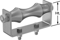 |
Support lines that expand and contract. The roller on these supports compensates for movement in your line from changing temperatures. Often used outdoors, these supports are galvanized steel to resist corrosion in wet environments. Bolt them to the floor, beams, or brackets. They can also be welded into place.
Mounting Hole | Thread | Temp. Range, ° F | ||||||||||||||||
|---|---|---|---|---|---|---|---|---|---|---|---|---|---|---|---|---|---|---|
For OD | For Pipe Size | Wt. Cap., lb. | Lg. | Wd. | Ht. | Roller Material | Dia. | No. of | Ctr.-to-Ctr. | Mounting Hardware Included | Size | Lg. | Min. | Max. | Each | |||
Galvanized Steel | ||||||||||||||||||
| 2 1/2", 64 mm | 2 | 600 | 4 1/4" | 1 1/4" | 1 1/2" | Galvanized Cast Iron | 3/8" | 2 | 1 1/4" | Yes | 3/8"-16 | 1 1/2" | -20 | 400 | 6581N11 | 000000 | ||
| 3 5/8", 92 mm | 3 | 700 | 5 3/4" | 1 1/4" | 1 3/4" | Galvanized Cast Iron | 3/8" | 2 | 2" | Yes | 3/8"-16 | 1 1/2" | -20 | 400 | 6581N12 | 00000 | ||
| 4 1/2", 114 mm | 4 | 750 | 6 5/8" | 1 1/2" | 2 13/16" | Galvanized Cast Iron | 1/2" | 2 | 2" | Yes | 1/2"-13 | 1 1/2" | -20 | 400 | 6581N2 | 00000 | ||
| 6 3/4", 171 mm | 6 | 1,070 | 9 7/8" | 2" | 2 3/4" | Galvanized Cast Iron | 1/2" | 2 | 3 1/8" | Yes | 1/2"-13 | 1 1/2" | -20 | 400 | 6581N14 | 00000 | ||
| 8 3/4", 222 mm | 8 | 1,350 | 12 1/8" | 2" | 3" | Galvanized Cast Iron | 5/8" | 2 | 3 3/8" | Yes | 5/8"-11 | 1 1/2" | -20 | 400 | 6581N15 | 00000 | ||
| 11", 279 mm | 10 | 1,730 | 14 3/8" | 2" | 3 5/8" | Galvanized Cast Iron | 5/8" | 2 | 5 1/4" | Yes | 5/8"-11 | 2" | -20 | 400 | 6581N16 | 000000 | ||
| 12 7/8", 327 mm | 12 | 2,400 | 16 1/2" | 2" | 4 1/8" | Galvanized Cast Iron | 5/8" | 2 | 5 1/2" | Yes | 5/8"-11 | 2" | -20 | 400 | 6581N17 | 000000 | ||
| 14 1/4", 362 mm | 14 | 3,130 | 18 1/4" | 2 1/2" | 4 11/16" | Galvanized Cast Iron | 3/4" | 2 | 6 1/2" | Yes | 3/4"-10 | 2" | -20 | 400 | 6581N18 | 000000 | ||
| 16 1/4", 413 mm | 16 | 3,970 | 20 1/2" | 3" | 5 3/8" | Galvanized Cast Iron | 3/4" | 2 | 8 1/4" | Yes | 3/4"-10 | 2 1/2" | -20 | 400 | 6581N19 | 000000 | ||
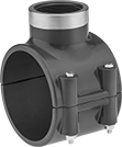
FM-Approved Medium-Pressure Iron and Steel Grooved-End Pipe Fittings
Clamps with Gasket
 |
Grooved-End Clamp-On Female |
Grooved-End-Clamp-On Fitting Connection—Clamps have a two-piece housing that can remain intact for installation.
For Pipe Size | For Pipe OD | Color | Max. Pressure @ Temp. | Gasket Material | Certification | Each | |||
|---|---|---|---|---|---|---|---|---|---|
Grooved-End Clamp-On Female | |||||||||
| 2 | 2 3/8" | Orange | 750 psi @ 72° F | Buna-N | FM Approved, UL Listed | 5723T327 | 000000 | ||
| 2 | 2 3/8" | Orange | 750 psi @ 72° F | EPDM | FM Approved, UL Listed | 5723T321 | 00000 | ||
| 2 1/2 | 2 7/8" | Orange | 750 psi @ 72° F | Buna-N | FM Approved, UL Listed | 5723T83 | 00000 | ||
| 2 1/2 | 2 7/8" | Orange | 750 psi @ 72° F | EPDM | FM Approved, UL Listed | 5723T81 | 00000 | ||
| 3 | 3 1/2" | Orange | 750 psi @ 72° F | Buna-N | FM Approved, UL Listed | 5723T328 | 00000 | ||
| 3 | 3 1/2" | Orange | 750 psi @ 72° F | EPDM | FM Approved, UL Listed | 5723T322 | 00000 | ||
| 4 | 4 1/2" | Orange | 750 psi @ 72° F | Buna-N | FM Approved, UL Listed | 5723T329 | 000000 | ||
| 4 | 4 1/2" | Orange | 750 psi @ 72° F | EPDM | FM Approved, UL Listed | 5723T323 | 000000 | ||
| 6 | 6 5/8" | Orange | 700 psi @ 72° F | EPDM | FM Approved, UL Listed | 5723T92 | 000000 | ||
| 6 | 6 5/8" | Orange | 750 psi @ 72° F | Buna-N | FM Approved, UL Listed | 5723T84 | 000000 | ||
Replacement Gaskets
 |
For Pipe Size | OD | ID | Thk. | Color | Temp. Range, ° F | Each | |||
|---|---|---|---|---|---|---|---|---|---|
| 2 | 3 5/16" | 2 3/8" | 1 3/32" | Black | -30 to 250 | 5723T324 | 000000 | ||
| 2 1/2 | 3 3/4" | 2 7/8" | 1 3/32" | Black | -20 to 180 | 5723T87 | 00000 | ||
| 3 | 4 1/2" | 3 1/2" | 1 3/32" | Black | -30 to 250 | 5723T325 | 00000 | ||
| 3 | 4 1/2" | 3 1/2" | 1 3/32" | Black | -20 to 180 | 5723T332 | 00000 | ||
| 4 | 5 3/4" | 4 1/2" | 1 7/32" | Black | -30 to 250 | 5723T326 | 000000 | ||
| 4 | 5 3/4" | 4 1/2" | 1 7/32" | Black | -20 to 180 | 5723T333 | 000000 | ||
| 6 | 8" | 6 5/8" | 1 3/16" | Black | -30 to 250 | 5723T93 | 000000 | ||
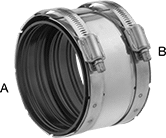
Easy-Access CPVC Pipe Fittings for Chemicals
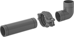 |
Also known as Victaulic fittings, these have grooved ends that connect to pipe with a clamp, so you can access your chemical process line for routine maintenance. Fittings are CPVC, which has excellent chemical resistance to withstand a variety of salt solutions, acids, and other harsh substances. They are comparable to Corzan. Fittings meet ASTM D1784 specifications and testing requirements for material quality.
Warning: Never use plastic pipe fittings, flanges, and pipe with compressed air or gas.
Clamp Connectors with Gasket
 |
Grooved-End Clamp-On Female |
Clamp Adapters with Gasket
 |
Grooved-End Clamp-On Female × Grooved-End Clamp-On Female |
Clamp adapters let you connect CPVC grooved-end pipe fittings and pipe to metal grooved-end pipe fittings and pipe.
Clamp Reducers with Gasket
 |
Grooved-End Clamp-On Female × Grooved-End Clamp-On Female |
Clamp reducers allow you to connect CPVC grooved-end pipe fittings and pipe and transition from a larger pipe size to a smaller pipe size.
For Pipe Size | For Pipe OD | ||||||||||
|---|---|---|---|---|---|---|---|---|---|---|---|
(A) | (B) | (A) | (B) | Material | Color | Max. Pressure @ Temp. | Gasket Material | Each | |||
Grooved-End Clamp-On Female × Grooved-End Clamp-On Female | |||||||||||
| 3 | 2 | 3 1/2" | 2 3/8" | Enamel-Coated Iron | Orange | 300 psi @ 72° F | EPDM | 2663N33 | 000000 | ||
| 4 | 2 | 4 1/2" | 2 3/8" | Enamel-Coated Iron | Orange | 300 psi @ 72° F | EPDM | 2663N35 | 000000 | ||
| 4 | 3 | 4 1/2" | 3 1/2" | Enamel-Coated Iron | Orange | 300 psi @ 72° F | EPDM | 2663N34 | 000000 | ||
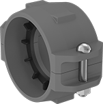
Snug-Fit Clamp Pipe Hangers
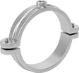 |
Place pipe between the hanger halves and adjust the side bolts for a tighter fit than other pipe hangers. When closed, the split ring forms a complete circle around the pipe for 360° support with no gaps. Mount by twisting a threaded rod through the threaded hole.
Zinc-Plated Iron—Mildly corrosion resistant, so these hangers are ideal for dry or slightly humid environments.
Epoxy-Coated Iron—Resist corrosion better than zinc-plated iron.
ID | For Conduit Trade Size | ||||||||||||
|---|---|---|---|---|---|---|---|---|---|---|---|---|---|
Inch | Metric, mm | For Pipe Size | For Copper Tube Size | EMT | IMC | Rigid | For Thread Size | Wt. Cap., lb. | Mounting Hole Dia. | Each | |||
Iron | |||||||||||||
| 11/16" | 17 | 3/8 | 1/2 | — | — | 3/8 | 3/8"-16 | 180 | 3/8" | 3023T67 | 00000 | ||
| 7/8" | 22 | 1/2 | 3/4 | 3/4 | 1/2 | 1/2 | 3/8"-16 | 180 | 3/8" | 3023T68 | 0000 | ||
| 1 1/16" | 27 | 3/4 | — | — | 3/4 | 3/4 | 3/8"-16 | 180 | 3/8" | 3023T69 | 0000 | ||
| 1 5/16" | 33 | 1 | — | — | 1 | 1 | 3/8"-16 | 180 | 3/8" | 3023T71 | 0000 | ||
| 1 11/16" | 43 | 1 1/4 | 1 1/2 | — | 1 1/4 | 1 1/4 | 3/8"-16 | 180 | 3/8" | 3023T72 | 0000 | ||
| 1 7/8" | 48 | 1 1/2 | — | — | 1 1/2 | 1 1/2 | 3/8"-16 | 180 | 3/8" | 3023T73 | 0000 | ||
| 2 3/8" | 60 | 2 | — | — | 2 | 2 | 3/8"-16 | 180 | 3/8" | 3023T74 | 00000 | ||
| 2 7/8" | 73 | 2 1/2 | — | 2 1/2 | 2 1/2 | 2 1/2 | 1/2"-13 | 300 | 1/2" | 3023T15 | 00000 | ||
| 3 1/2" | 89 | 3 | — | 3 | 3 | 3 | 1/2"-13 | 300 | 1/2" | 3023T16 | 00000 | ||
| 4 1/2" | 114 | 4 | — | 4 | 4 | 4 | 1/2"-13 | 300 | 1/2" | 3023T48 | 00000 | ||
Zinc-Plated Iron | |||||||||||||
| 11/16" | 17 | 3/8 | 1/2 | — | — | 3/8 | 3/8"-16 | 180 | 3/8" | 3023T22 | 0000 | ||
| 7/8" | 22 | 1/2 | 3/4 | 3/4 | 1/2 | 1/2 | 3/8"-16 | 180 | 3/8" | 3023T23 | 0000 | ||
| 1 1/16" | 27 | 3/4 | — | — | 3/4 | 3/4 | 3/8"-16 | 180 | 3/8" | 3023T24 | 0000 | ||
| 1 5/16" | 33 | 1 | — | — | 1 | 1 | 3/8"-16 | 180 | 3/8" | 3023T25 | 0000 | ||
| 1 11/16" | 43 | 1 1/4 | 1 1/2 | — | 1 1/4 | 1 1/4 | 3/8"-16 | 180 | 3/8" | 3023T26 | 0000 | ||
| 1 7/8" | 48 | 1 1/2 | — | — | 1 1/2 | 1 1/2 | 3/8"-16 | 180 | 3/8" | 3023T27 | 00000 | ||
| 2 3/8" | 60 | 2 | — | — | 2 | 2 | 3/8"-16 | 180 | 3/8" | 3023T28 | 00000 | ||
| 2 7/8" | 73 | 2 1/2 | — | 2 1/2 | 2 1/2 | 2 1/2 | 1/2"-13 | 300 | 1/2" | 3023T29 | 00000 | ||
| 3 1/2" | 89 | 3 | — | 3 | 3 | 3 | 1/2"-13 | 300 | 1/2" | 3023T31 | 00000 | ||
| 4 1/2" | 114 | 4 | — | 4 | 4 | 4 | 1/2"-13 | 300 | 1/2" | 3023T32 | 00000 | ||
Epoxy-Coated Iron | |||||||||||||
| 1/2" | 12 | — | 3/8 | — | — | — | 3/8"-16 | 180 | 3/8" | 3023T33 | 0000 | ||
| 5/8" | 15 | — | 1/2 | — | — | — | 3/8"-16 | 180 | 3/8" | 3023T34 | 0000 | ||
| 7/8" | 22 | — | 3/4 | — | — | — | 3/8"-16 | 180 | 3/8" | 3023T51 | 0000 | ||
| 1 1/8" | 28 | — | 1 | — | — | — | 3/8"-16 | 180 | 3/8" | 3023T52 | 0000 | ||
| 1 3/8" | 34 | — | 1 1/4 | — | — | — | 3/8"-16 | 180 | 3/8" | 3023T53 | 0000 | ||
| 1 5/8" | 41 | — | 1 1/2 | — | 1 1/4 | — | 3/8"-16 | 180 | 3/8" | 3023T54 | 00000 | ||
| 2 1/8" | 53 | — | 2 | — | — | — | 3/8"-16 | 180 | 3/8" | 3023T55 | 00000 | ||
Drain, Waste, and Vent Iron and Steel Pipe Fittings
Clamp Connectors
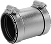 |
Clamp On |
For Pipe Size | Material | Max. Pressure @ Temp. | Sleeve Material | Each | |||
|---|---|---|---|---|---|---|---|
Clamp On | |||||||
| 1 1/2 | 304 Stainless Steel | 15 psi @ 72° F | Neoprene | 6820K21 | 000000 | ||
| 2 | 304 Stainless Steel | 15 psi @ 72° F | Neoprene | 6820K22 | 00000 | ||
| 3 | 304 Stainless Steel | 15 psi @ 72° F | Neoprene | 6820K23 | 00000 | ||
| 4 | 304 Stainless Steel | 15 psi @ 72° F | Neoprene | 6820K24 | 00000 | ||
| 5 | 304 Stainless Steel | 15 psi @ 72° F | Neoprene | 6820K25 | 00000 | ||
| 6 | 304 Stainless Steel | 15 psi @ 72° F | Neoprene | 6820K26 | 00000 | ||
| 8 | 304 Stainless Steel | 15 psi @ 72° F | Neoprene | 6820K28 | 000000 | ||
| 10 | 304 Stainless Steel | 15 psi @ 72° F | Neoprene | 6820K29 | 000000 | ||
| 12 | 304 Stainless Steel | 15 psi @ 72° F | Neoprene | 6820K222 | 000000 | ||

Roller Loop Pipe Hangers
 |
Compensate for linear movement as pipes expand and contract. The roller turns to accommodate motion as pipes carry fluids and gases at fluctuating temperatures or pressures. Attach to the ceiling with a threaded rod and nut (sold separately) or other fastener.
ID | For Conduit Trade Size | ||||||||||||
|---|---|---|---|---|---|---|---|---|---|---|---|---|---|
Inch | Metric, mm | For Pipe Size | EMT | IMC | Rigid | For Thread Size | Wt. Cap., lb. | Mounting Hole Dia. | No. of Nuts Req. | Each | |||
Steel | |||||||||||||
| 2 3/8" | 60 | 2 | — | 2 | 2 | 3/8"-16 | 150 | 7/16" | 1 | 3084T31 | 000000 | ||
| 2 7/8" | 73 | 2 1/2 | 2 1/2 | 2 1/2 | 2 1/2 | 1/2"-13 | 220 | 9/16" | 1 | 3084T32 | 00000 | ||
| 3 1/2" | 89 | 3 | 3 | 3 | 3 | 1/2"-13 | 310 | 9/16" | 1 | 3084T33 | 00000 | ||
| 4" | 102 | 3 1/2 | 3 1/2 | 3 1/2 | 3 1/2 | 1/2"-13 | 390 | 9/16" | 1 | 3084T34 | 00000 | ||
| 4 1/2" | 114 | 4 | 4 | 4 | 4 | 5/8"-11 | 470 | 11/16" | 1 | 3084T35 | 00000 | ||
| 5 9/16" | 141 | 5 | — | — | 5 | 5/8"-11 | 680 | 11/16" | 1 | 3084T36 | 00000 | ||
| 6 5/8" | 168 | 6 | — | — | 6 | 3/4"-10 | 780 | 13/16" | 1 | 3084T37 | 00000 | ||
| 8 5/8" | 219 | 8 | — | — | — | 3/4"-10 | 780 | 13/16" | 1 | 3084T38 | 000000 | ||
| 10 3/4" | 273 | 10 | — | — | — | 7/8"-9 | 960 | 15/16" | 1 | 3084T39 | 000000 | ||
| 12 3/4" | 324 | 12 | — | — | — | 7/8"-9 | 1,200 | 15/16" | 1 | 3084T41 | 000000 | ||
| 14" | 356 | 14 | — | — | — | 1"-8 | 1,200 | 1 1/8" | 1 | 3084T42 | 000000 | ||
| 16" | 406 | 16 | — | — | — | 1"-8 | 1,200 | 1 1/8" | 1 | 3084T43 | 000000 | ||
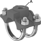
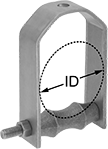
Beam Clamps for Pipe, Tube, and Conduit
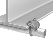 | 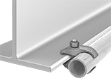 |
For Perpendicular Mounting | For Parallel Mounting |
Secure lines of pipe, tubing, and conduit to the flange of a beam.
Galvanized Iron—Galvanized iron clamps have good corrosion resistance.
For OD | For Beam Thk. | For Perpendicular Mounting | For Parallel Mounting | |||||||||||
|---|---|---|---|---|---|---|---|---|---|---|---|---|---|---|
For Beam Shape | Inch | Metric, mm | For Pipe Size | Min. | Max. | Wt. Cap. | Mount Type | Throat Dp. | Each | Each | ||||
Bottom and Top Beam Mount | ||||||||||||||
Galvanized Iron | ||||||||||||||
| Flat, Taper | 5/8" | 16 | 3/8 | 1/8" | 3/4" | Not Rated | Clamp On | 7/16" | 29585T81 | 000000 | ——— | 0 | ||
| Flat, Taper | 7/8" | 22 | 1/2 | 1/8" | 3/4" | Not Rated | Clamp On | 7/16" | 29585T82 | 00000 | 8868T61 | 000000 | ||
| Flat, Taper | 1" | 25 | 3/4 | 1/8" | 3/4" | Not Rated | Clamp On | 7/16" | 29585T83 | 00000 | 8868T62 | 00000 | ||
| Flat, Taper | 1 5/16" | 33 | 1 | 1/8" | 3/4" | Not Rated | Clamp On | 7/16" | 29585T84 | 00000 | 8868T63 | 00000 | ||
| Flat, Taper | 1 5/8" | 41 | 1 1/4 | 1/8" | 3/4" | Not Rated | Clamp On | 7/16" | 29585T85 | 00000 | 8868T64 | 00000 | ||
| Flat, Taper | 1 7/8" | 48 | 1 1/2 | 1/8" | 3/4" | Not Rated | Clamp On | 7/16" | 29585T86 | 00000 | 8868T65 | 00000 | ||
| Flat, Taper | 2 3/8" | 60 | 2 | 1/8" | 3/4" | Not Rated | Clamp On | 7/16" | 29585T87 | 00000 | 8868T66 | 00000 | ||
