McMaster-Carr logo
    Filter by
    Material
    Enclosure Rating
    Industrial Info Compare
    System of Measurement
    Panel Cutout Diameter
    Switching Voltage
    Industrial Info Snippet
    Housing Material
    Switch Starting Position
    Industrial Info Compare
    U.S.–Mexico–Canada Agreement (USMCA) Qualifying
    Industrial Info Snippet
    DFARS Specialty Metals
    Export Control Classification Number (ECCN)
    Industrial Info Snippet
    Mounting Location
    Wire Connection
    Actuator Material
    Switching Current
    Industrial Info Snippet
    Number of Circuits Controlled
    Switch Action
    Conduit Thread Type
    Industrial Info Compare
    Mount Type
    Number of Terminals
    Enter e-mail addresses in the fields below
    Message
    Cancel
    Comments
    E-mail address (if you would like a response)
    39 Products

    Panel-Mount Switch Size Adapters

    Image of ProductInUse. Adapter Shown with Panel-Mount Switch (Not Included). Front orientation. Exploded view. Contains Annotated. Switch Mounts. Panel-Mount Switch Size Adapters.
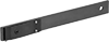
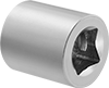
    Image of Product. Adapter. Front orientation. Switch Mounts. Panel-Mount Switch Size Adapters.

    Adapter Shown with Panel-Mount

    Switch (Not Included)

    Adapter

    Install 22 mm panel-mount switches into 30 mm cutouts.
    For Panel Cutout Diameter
    Material
    Each
    22 mm (7/8") to 30 mm (1 3/16")Metal6959N1100000

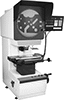
    Vertical Benchtop Optical Comparators

    By projecting a magnified shadow or image of your part onto a screen, these optical comparators give you an easy way to measure and inspect its precise features. They work similarly to overhead projectors, but with fixed magnification to preserve proportions. Because of how easy they are to set up and use, they’re a staple in most machine shops. They shine light from above, so they’re best for inspecting flat parts, such as gaskets and O-rings. Unlike traditional optical comparators, these comparators are compact to fit easily on a benchtop.
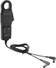
    To use these comparators, choose profile or surface lighting. Profile lighting creates a shadow of your part, which you can use to plot points for precise measurements. To plot each point, move the stage the part rests on until the point lines up with the crosshair on the projector screen. For precision, the stage moves in increments thinner than a sheet of paper. Surface lighting makes these comparators work like an illuminated magnifier, blanketing the part with even light to reveal scratches, dents, and other surface flaws.
    Save the measurements you’ve gathered for later by exporting the data as a text file using an RS-232 cord (not included).
    Optical Comparators
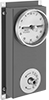
    Image of Product. Front orientation. Optical Comparators. Vertical Benchtop Optical Comparators, Optical Comparators.
    Image of Specification. Numeric Display Screen. Front orientation. Contains Border. Numeric Display. Vertical Benchtop Optical Comparators.

    Numeric Display Screen

    Stage
    Stage Travel
    Distance
    Overall
    Electrical
    Magnification
    Load Cap.,
    lb.
    Lg.
    Wd.
    X
    Axis
    Y
    Axis
    Stage Travel
    Resolution
    Projector
    Screen Dia.
    Display Screen
    Type
    Ht.
    Wd.
    Dp.
    Connection
    No. of
    Blades
    Cord Lg.,
    ft.
    Each
    10X87 3/4"3 3/4"6"2"0.00002"12"Numeric44"22"31"Straight Blade356378N110000000000
    Accessories for Optical Comparators
    Optical Comparators with Edge Detection
    Image of Product. Front orientation. Optical Comparators. Vertical Benchtop Optical Comparators, Optical Comparators with Edge Detection.
    Image of Specification. Graphic Display Screen. Front orientation. Contains Border. Graphic Display. Vertical Benchtop Optical Comparators.

    Graphic Display Screen

    Optical comparators with edge detection increase accuracy and efficiency by reducing human error. No need to identify each edge yourself with the crosshair—these comparators register whether they are passing over your object's shadow or a gap, such as a hole or cutout. The graphic display screen shows a visual representation of the part you’re measuring, making it easy to identify and measure specific features. To make sure each part is inspected the same way, create a program that guides anyone using the comparator on what steps to follow.
    Stage
    Stage Travel
    Distance
    Overall
    Electrical
    Magnification
    Load Cap.,
    lb.
    Lg.
    Wd.
    X
    Axis
    Y
    Axis
    Stage Travel
    Resolution
    Projector
    Screen Dia.
    Display Screen
    Type
    Ht.
    Wd.
    Dp.
    USB
    Std.
    Connection
    No. of
    Blades
    Cord Lg.,
    ft.
    Each
    10X87 3/4"3 3/4"6"2"0.00002"12"Graphic44"22"31"2.0Straight Blade, USB-B356378N120000000000
    Accessories for Optical Comparators

    Build-Your-Own Limit Switches

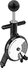
    Image of Product. Style L. Front orientation. Limit Switches. Build-Your-Own Limit Switches, Wobble Stick Actuator, Style L.

    Style

    L

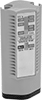
    Combine an actuator and a switch to assemble the exact limit switch you need. These switches have the rapid-closing action of a snap-acting switch, but have a larger actuator for large objects. When an object in motion comes into contact with the actuator, it sends a signal to open or close a circuit. They’re often used for conveyor systems and elevators. Each actuator style is compatible with all housing styles and vice versa.
    Actuators
    Image of Product. Style L. Front orientation. Limit Switches. Build-Your-Own Limit Switches, Wobble Stick Actuator, Style L.

    Style

    L

    Wobble Stick Actuator—Wobble stick actuators open or close circuits when an object hits the flexible arm. The arm has a 360° range of motion, so it can be actuated from any direction. This means that if there’s a jam, these switches are less likely to break than switches that are aligned to a specific direction.
    Style
    Actuator
    Material
    Actuator
    Ht.
    Each
    Wobble Stick Actuator
    LMetal7.9"7976N26000000
     

    Frame-Mounted Safety Switches

    Image of ProductInUse. Key Shown Actuating from the Side. Front orientation. Safety Switches. Frame-Mounted Safety Switches.
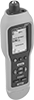
    Key Shown Actuating from the Side
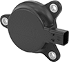
    Image of Product. Front orientation. Safety Switches. Frame-Mounted Safety Switches, Style F.

    Style F

    Image of Product. Front orientation. Safety Switches. Frame-Mounted Safety Switches, Style G.

    Style G

    Also known as interlock switches, these ensure the safety of personnel by automatically shutting off power to machinery when an access door opens. Mount the switch to the door frame and mount a key to the door so that the key is inserted into the switch when the door is closed. When the door opens, the key is removed from the switch and the machine shuts down. They’re often used with machine guards for large robots.
    For the Manufacturer User Manual, click on a part number and select Product Detail.
    Styles F and G—Style A-G switches have positive-force, normally closed contacts that will open a circuit when the switch is actuated even if a spring fails or the contacts stick.
    IP67 Enclosure Rating—IP67 rated switches protect against temporary submersion.
    Key Included—All switches require an actuator key, but not all include one—check whether you need to pick out a separate actuator key. For some switch styles, you can also select the mounting orientation of the key.
    Housing
    Conduit
    Style
    No. of Circuits
    Controlled
    Switch Starting
    Position
    Switch
    Action
    No. of
    Terminals
    Switch
    Designation
    Switching Current @ Voltage
    Max. Voltage
    Ht.
    Wd.
    Dp.
    Trade
    Size
    Thread
    Size
    Thread
    Type
    Key
    Included
    Enclosure
    Rating
    Each
    Screw-Terminal Wire Connection with Positive-Force Normally Closed Contacts
    F21 Off and 1 On
    Maintained
    4DPST-1NO/1NC
    2 amp @ 400V AC400V AC4.4"1.6"1.6"M20
    Metric
    NoIP67
    65665K1120000000
    F21 Off and 1 On
    Maintained
    4DPST-1NO/1NC
    2 amp @ 400V AC400V AC4.4"1.6"1.6"1/2
    BSPP
    NoIP67
    65665K111000000
    F21 Off and 1 On
    Maintained
    4DPST-1NO/1NC
    2 amp @ 400V AC400V AC4.4"1.6"1.6"1/2
    NPT
    NoIP67
    65665K105000000
    F22 On
    Maintained
    4DPST-NC
    2 amp @ 400V AC400V AC4.4"1.6"1.6"M20
    Metric
    NoIP67
    65665K113000000
    F22 On
    Maintained
    4DPST-NC
    2 amp @ 400V AC400V AC4.4"1.6"1.6"1/2
    BSPP
    NoIP67
    65665K108000000
    F22 On
    Maintained
    4DPST-NC
    2 amp @ 400V AC400V AC4.4"1.6"1.6"1/2
    NPT
    NoIP67
    65665K109000000
     
    Screw-Terminal Wire Connection with Positive-Force Normally Closed Contacts and Rotating Head
    G31 Off and 2 On
    Maintained
    63PST-1NO/2NC
    10 amp @ 230V AC, 4 amp @ 24V DC250V AC
    24V DC
    4.3"1.6"1.4"M20
    Metric
    NoIP67
    65665K19000000
     
    Actuator Keys

    Build-Your-Own Air-Actuated Foot Switches

    Combine a foot-pedal actuator with a switching mechanism to build a complete switch that allows for convenient, hands-free operation. These switches use air pressure to turn circuits on or off, keeping live electrical circuits away from work areas.
    Actuators
    Image of Product. Front orientation. Air-Actuated Switches. Build-Your-Own Air-Actuated Foot Switches, Actuators.
    Lg.
    Wd.
    Ht.
    Tube
    ID
    Tube
    OD
    Material
    Enclosure
    Rating
    Includes
    Each
    6"3 5/8"1 7/8"1/8"1/4"MetalIP02
    6 ft. Tubing7467K510000000
     
    Switching Mechanisms
    Image of Product. Front orientation. Air-Actuated Switches. Build-Your-Own Air-Actuated Foot Switches, Switching Mechanisms.

    Switching

    Mechanisms

    No. of Circuits
    Controlled
    Switch Starting
    Position
    Switch
    Action
    No. of
    Terminals
    Switch
    Designation
    Switching Current
    @ Voltage
    Quick-Disconnect
    Tab Wd.
    Component
    Certification
    Specs.
    Met
    Each
    11 Off or 1 On
    Momentary
    3SPDT
    21 amp @ 250V AC0.25"Switching MechanismCE Marked, CSA Certified, UL Listed
    UL 5086573K82000000
    11 Off or 1 On
    Maintained
    3SPDT
    21 amp @ 250V AC0.25"Switching MechanismCE Marked, CSA Certified, UL Listed
    UL 5086573K8100000
    22 Off or 2 On
    Momentary
    6DPDT
    21 amp @ 250V AC0.25"Switching MechanismUL Listed
    UL 5086573K8400000
    22 Off or 2 On
    Maintained
    6DPDT
    21 amp @ 250V AC0.25"Switching MechanismCE Marked, CSA Certified, UL Listed
    UL 5086573K8300000

    Remote-Reading Panel-Mount Freezer Thermometers with Audible Alarm

    Image of Product. Front orientation. Thermometers. Remote-Reading Panel-Mount Freezer Thermometers with Audible Alarm.
    Protect temperature-sensitive materials in refrigerators and freezers with one of these thermometers that sound an alarm and flash the display when temperature rises above your activation point.
    Probe
    Mounting
    Holes
    For Panel
    Cutout
    Input
    Temp. Range
    Actuation Point
    Temp. Range
    Temp.
    Resolution
    Accuracy
    Cable Lg.,
    ft.
    Dia.
    Lg.
    No.
    of
    Dia.
    Fasteners
    Included
    Ht.
    Wd.
    Ht.
    Wd.
    AC Voltage,
    V AC
    DC Voltage,
    V DC
    Electrical
    Connection
    Freq.,
    Hz
    Each
    -25° F to 99° F/-32° C to 38° C-15° F to 50° F/
    -26° C to 10° C
    1° F/1° C±3° F63/8"7/8"27/32"No3 7/8"2 7/8"5"3 1/8"10.5 to 2812 to 28Wire Leads603825K20000000
    Supplies

    Clamp-On Noncontact Temperature Sensors for Pipe

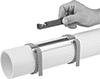
    Image of ProductInUse. Sensor Shown Installed (Adapter Sold Separately). Back orientation. Noncontact Temperature Sensors. Clamp-On Noncontact Temperature Sensors for Pipe.

    Sensor Shown Installed

    (Adapter Sold Separately)

    Check the inside temperature of your pipe from the outside. A good choice for when contamination is a concern, these sensors don’t touch what’s inside your line. They sit on the outside, so they won’t corrode, gunk up, or break from your line's flow. A clamp makes them quick to attach and easy to reposition—there’s no need to drill into your pipe or drain your line. They have internal sensors to record the pipe’s thermal conductivity, which is used to calculate your line’s temperature.
    4 mA to 20 mA Output Signal—The information is sent through a 4-20 mA signal, so you can read the temperature on controllers and data loggers.
    For Metal Pipes—Sensors for metal pipe are preconfigured for Schedule 40 stainless steel pipe. They won’t work with plastic pipe.
    For
    Pipe
    M12 Male
    Electrical Connection
    Size
    Schedule
    Temp. Measurement
    Range, ° F
    Accuracy
    Response
    Time, sec.
    Ht.
    Wd.
    Dp.
    No. of
    Poles
    Coding
    Housing
    Material
    Operating
    Temp. Range, ° F
    Enclosure
    Rating
    Electrical Connection
    Gender
    Each
    4 mA to 20 mA Output Signal
     
    For Metal Pipes
    1
    40
    -4 to 212±0.9° F52 3/8"2 1/2"2"8A
    Nylon
    32 to 100IP67
    Male5780N110000000
    2
    40
    -4 to 212±0.9° F52 3/8"2 1/2"2"8A
    Nylon
    32 to 100IP67
    Male5780N13000000
    2 1/2
    40
    -4 to 212±0.9° F52 3/8"2 1/2"1 7/8"8A
    Nylon
    32 to 100IP67
    Male5780N15000000
    3
    40
    -4 to 212±0.9° F52 3/8"2 1/2"1 7/8"8A
    Nylon
    32 to 100IP67
    Male5780N16000000
    4
    40
    -4 to 212±0.9° F52 3/8"2 1/2"1 7/8"8A
    Nylon
    32 to 100IP67
    Male5780N17000000
     
    Adapters
    back to top