Filter by
Actuator Style
System of Measurement
Housing Height
Switch Starting Position
Wire Connection

Switch Designation
Number of Terminals
Actuator Height
Electrical Connection
Export Control Classification Number (ECCN)
Maximum Temperature
Minimum Temperature
Switch Type
U.S.–Mexico–Canada Agreement (USMCA) Qualifying
Actuation Torque
DFARS Specialty Metals
Heavy Duty Limit Switches
 |  |  |
Housing | ||||||||||||||||||||
|---|---|---|---|---|---|---|---|---|---|---|---|---|---|---|---|---|---|---|---|---|
Actuation Direction | No. of Circuits Controlled | Switch Starting Position | Switch Action | Switch Designation | Switching Current @ Voltage | Max. Voltage | Actuation Torque, in·ozf | Operating Temp. Range, ° F | Actuator Ht. | For Max. Cable OD | No. of Terminals | Lg. | Ht. | Dp. | Housing Material | Enclosure Rating | Each | |||
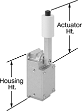
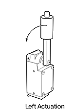
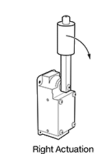
Roller Lever Actuator | ||||||||||||||||||||
Screw-Terminal Wire Connection | ||||||||||||||||||||
| Left | 2 | 2 Off | Momentary | DPST-NO | 20 amp @ 120V AC, 5 amp @ 120V DC | 600V AC 600V DC | 150 | -10 to 185 | 5.7" | 0.5" | 4 | 2.3" | 5" | 3.4" | Aluminum | NEMA 4, NEMA 13, IP67 | 7904N22 | 0000000 | ||
| Right | 2 | 2 Off | Momentary | DPST-NO | 20 amp @ 120V AC, 5 amp @ 120V DC | 600V AC 600V DC | 150 | -10 to 185 | 5.7" | 0.5" | 4 | 2.3" | 5" | 2" | Aluminum | NEMA 4, NEMA 13, IP67 | 7904N21 | 000000 | ||
Valve Position Sensors
 |
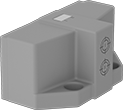 |
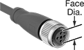
With Flat Face |
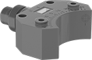 |
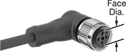
With Curved Face |
4-Pole M12 Plug |
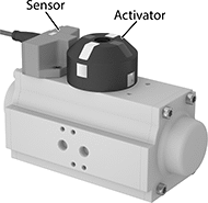
These sensors detect when a valve is open or closed, supporting flow and temperature control within your system. Secure the sensor to your valve actuator’s mounting holes, and attach an activator (sold separately) to the actuator's shaft. As the actuator opens and closes the valve, the activator rotates until its targets align with the sensor's two inductive sensors. Once they’re aligned, your system will know that the valve is either open or closed—offering reliable feedback on your valve’s position. Connect these sensors to programmable logic controllers (PLCs) to support automated processes. They meet various national and international safety standards, and they’re rated IP67 to protect against dust, washdowns, and temporary submersion.
To view wiring diagrams, select a part number and click Product Detail.
Curved Face—Sensors with a curved face minimize pinch points between the sensor and activator, making them good for manually-controlled valves.
Plug In—Sensors with a 4-pole M12 plug connect to cables with a socket (sold separately), so you can quickly connect and disconnect them.
Switch Starting Position | Switching Freq., Hz | Max. Sensing Distance, mm | Output Digital Signal | Electrical Connection Type | Input Voltage, V DC | Current Output, mA | No. of Wire Leads | Lg., mm | Circuit Protection | Cable Lead Lg., ft. | Temp. Range, ° F | Enclosure Rating | Each | |||
|---|---|---|---|---|---|---|---|---|---|---|---|---|---|---|---|---|
Flat Face | ||||||||||||||||
With 4-Pole M12 Connection | ||||||||||||||||
| 2 Off | 500 | 3 | PNP | Plug In | 10 to 30 | 100 | — | 36 | Reverse Polarity | — | -10 to 155 | IP67 | 7122N16 | 0000000 | ||
With Wire Lead Connection | ||||||||||||||||
| 2 Off | 500 | 3 | PNP | Hardwire | 10 to 30 | 100 | 4 | 36 | Reverse Polarity | 16 | -10 to 155 | IP67 | 7122N18 | 000000 | ||
With Spring-Clamp Terminal Connection | ||||||||||||||||
| 2 Off | 500 | 3 | PNP | — | 10 to 30 | 100 | — | 78 | Reverse Polarity | — | -10 to 155 | IP67 | 7122N19 | 000000 | ||
Curved Face | ||||||||||||||||
With 4-Pole M12 Connection | ||||||||||||||||
| 2 Off | 500 | 3 | PNP | Plug In | 10 to 30 | 200 | — | 35 | Reverse Polarity | — | -10 to 155 | IP67 | 7122N11 | 000000 | ||
| 2 Off | 1,000 | 4 | PNP | Plug In | 10 to 30 | 200 | — | 42 | Reverse Polarity | — | -10 to 155 | IP67 | 7122N12 | 000000 | ||
With Wire Lead Connection | ||||||||||||||||
| 2 Off | 1,000 | 4 | PNP | Hardwire | 10 to 30 | 200 | 4 | 42 | Reverse Polarity | 6 1/2 | -10 to 155 | IP67 | 7122N14 | 000000 | ||
With Screw Terminal Connection | ||||||||||||||||
| 2 Off | 1,000 | 4 | PNP | — | 10 to 30 | 200 | — | 64 | Reverse Polarity | — | -10 to 155 | IP67 | 7122N15 | 000000 | ||
 |  |
Style A | Style B |
 |  |
Style C | Style D |
 |  |
Style E | Style F |
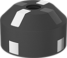
The position of metal targets on your activator determines when your sensor sends a signal to your PLC. To install, line up one of the activator's targets with one of the sensors while your valve is closed. Choose an activator that prompts your desired signal.
Styles A and F—Styles A and F prompt a signal from your sensor to your system when your valve is fully opened and closed.
Style B—Style B have a symmetrical design so you can position a sensor on both sides of the activator to create redundant signals and support safety applications.
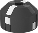
Style C—Style C prompt a signal from your sensor when your valve is not fully opened or closed—such as when your valve is in motion or stuck partially open.
Style D—Style D have customizable targets, prompting a signal when your valve reaches the position or range of motion you select.
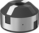
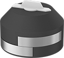
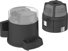
Style E—Style E include a housing that protects the activator against debris and damage. Colored on/off indicators make readings clear from far away. Use the included captive screws for easy mounting.
Housing | ||||||||||||||||
|---|---|---|---|---|---|---|---|---|---|---|---|---|---|---|---|---|
Style | For Max. Shaft Dia., mm | For Min. Shaft Dia., mm | For Shaft Lg., mm | Indicator Color | Dia., mm | Ht., mm | Body Material | Temp. Range, ° F | Mounting Fasteners Included | Dia., mm | Ht., mm | Material | Each | |||
For Flat Sensor Faces | ||||||||||||||||
| A | 58 | — | 20, 30 | — | 65 | 39 | Plastic | -10 to 155 | Yes | — | — | — | 7123N11 | 000000 | ||
| A | 90 | — | 20, 50 | — | 115 | 63 | Plastic | -10 to 155 | Yes | — | — | — | 7123N14 | 00000 | ||
| B | 58 | — | 20, 30 | — | 65 | 39 | Plastic | -10 to 155 | Yes | — | — | — | 7123N23 | 00000 | ||
| C | 58 | — | 20, 30 | — | 65 | 39 | Plastic | -10 to 155 | Yes | — | — | — | 7123N12 | 00000 | ||
| D | 53 | — | 20 | — | 65 | 40 | Plastic | -10 to 155 | Yes | — | — | — | 7123N22 | 00000 | ||
| E | 49 | — | 20, 30 | Black, Yellow | 65 | 68 | Plastic | -10 to 155 | Yes | 80 | 81.6 | Plastic | 7123N18 | 00000 | ||
| E | 49 | — | 20, 30 | Green, Red | 65 | 68 | Plastic | -10 to 155 | Yes | 80 | 81.6 | Plastic | 7123N13 | 00000 | ||
For Curved Sensor Faces | ||||||||||||||||
| F | — | 34 | 20, 30, 50 | — | 40 | 39 | Plastic | -10 to 155 | Yes | — | — | — | 7123N17 | 00000 | ||
| F | 34 | — | 20 | — | 40 | 32 | Plastic | -10 to 155 | Yes | — | — | — | 7123N15 | 00000 | ||
| F | 34 | — | 30 | — | 40 | 43 | Plastic | -10 to 155 | Yes | — | — | — | 7123N16 | 00000 | ||