


Filter by
Weight Capacity
Measures
Load Sensor Connection
Data Connection
Electrical Connection
Sensor Type
RoHS
Export Control Classification Number (ECCN)
DFARS Specialty Metals
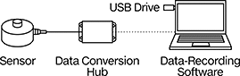
Ready-to-Use Tension and Compression Force Sensors
Round
 |  |
Button | Threaded Through Hole |
 |  |
Threaded Standoff | Threaded Stud |
 | |
Dual-Sided Threaded Stud |
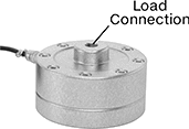
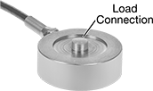
Button—Round sensors with a button are often used to measure weight in packaging machinery and for pressure sensing in medical device prototypes.
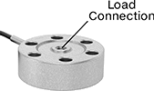
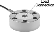
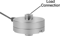
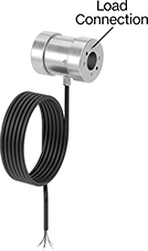
Threaded Standoff—Round sensors with threaded standoffs have a threaded hole to connect to eye bolts, rod ends, and threaded rods. They’re commonly mounted upside-down between a tank and a leveling mount to weight material in small tanks and silos.
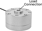
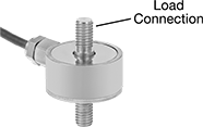
Dual-Sided Threaded Stud—Round sensors with a dual-sided threaded stud can monitor push-pull forces. For example, they might be used to test the durability of products that repeatedly fold and unfold.
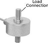
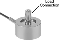
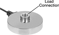
Threaded Stud—Round sensors with a threaded stud screw into equipment.
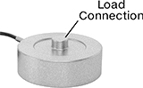
Threaded Through Hole—Round sensors with a threaded through hole are also known as pancake load cells. They can be bolted to surfaces in any orientation and are commonly used to measure clamping forces.
IP66 Enclosure Rating— IP66 sensors stand up to spraying water.
Legal-for-Trade—Legal-for-trade sensors are NTEP approved for use with equipment that measures materials sold by weight.
Enclosure Rating—IP-rated sensors seal out dust.
Load Connection | Mounting Holes | |||||||||||||||||
|---|---|---|---|---|---|---|---|---|---|---|---|---|---|---|---|---|---|---|
Wt. Cap. | Accuracy | Wt. Measuring Increments | Thread Size | Stud Lg. | Dia. | Ht. | Sensor Material | Temp. Range, ° F | Location | Fasteners Included | No. of | Diameter, mm | Thread Size | Enclosure Rating | Each | |||
Measures Tension and Compression | ||||||||||||||||||
With 1 Threaded Through Hole | ||||||||||||||||||
| 550 lb.; 250 kg | ±4.4 oz., ±125 g | 0.01 lb., 0.01 kg | M10 × 1.5 mm | — | 2 15/16" | 1" | Alloy Steel | 0 to 140 | Top | No | 6 | 6.5 | — | — | 6131N25 | 0000000 | ||
With 2 Dual-Sided Threaded Studs | ||||||||||||||||||
| 220 lb.; 100 kg | ±2.2 lb., ±1 kg | 0.01 lb., 0.001 kg | M6 × 1 mm | 5/16" | 1" | 1 7/16" | Alloy Steel | 0 to 140 | — | — | — | — | — | — | 6131N24 | 00000000 | ||
With 2 Threaded Standoffs | ||||||||||||||||||
| 5,000 lb.; 2,265 kg | ±2.5 lb., ±1.13 kg | 0.1 lb., 0.1 kg | 1/2"-20 | — | 4 1/8" | 2 1/2" | Alloy Steel | -40 to 175 | — | — | — | — | — | — | 6131N16 | 00000000 | ||
| 10,000 lb.; 4,535 kg | ±5 lb., ±2.2 kg | 0.1 lb., 0.1 kg | 1/2"-20 | — | 4 1/8" | 2 1/2" | Alloy Steel | -40 to 175 | — | — | — | — | — | — | 6131N17 | 00000000 | ||
| 25,000 lb.; 11,335 kg | ±12.5 lb., ±5.7 kg | 1 lb., 1 kg | 3/4"-16 | — | 4 3/4" | 3 1/16" | Alloy Steel | -40 to 175 | — | — | — | — | — | — | 6131N18 | 00000000 | ||
Measures Compression Not Legal-for-Trade | ||||||||||||||||||
With 1 Button | ||||||||||||||||||
| 550 lb.; 250 kg | ±4.4 oz., ±125 g | 0.01 lb., 0.01 kg | — | — | 2 1/16" | 7/8" | Alloy Steel | 0 to 140 | Bottom | No | 4 | — | M5 × 0.8 mm | IP66 | 6131N21 | 000000 | ||
| 1,100 lb.; 500 kg | ±8.8 oz., ±250 g | 0.1 lb., 0.01 kg | — | — | 2 1/16" | 7/8" | Alloy Steel | 0 to 140 | Bottom | No | 4 | — | M5 × 0.8 mm | IP66 | 6131N22 | 000000 | ||
| 2,200 lb.; 1,000 kg | ±1.1 lb., ±500 g | 0.1 lb., 0.01 kg | — | — | 2 1/16" | 7/8" | Alloy Steel | 0 to 140 | Bottom | No | 4 | — | M5 × 0.8 mm | IP66 | 6131N19 | 000000 | ||
| 4,405 lb.; 2,000 kg | ±2.2 lb., ±1 kg | 0.1 lb., 0.1 kg | — | — | 3 1/4" | 1 3/4" | Alloy Steel | 0 to 140 | Bottom | No | 3 | — | M8 × 1.25 mm | IP66 | 6131N14 | 000000 | ||
| 11,020 lb.; 5,000 kg | ±5.5 lb., ±2.5 kg | 1 lb., 0.1 kg | — | — | 3 1/4" | 1 3/4" | Alloy Steel | 0 to 140 | Bottom | No | 3 | — | M8 × 1.25 mm | IP66 | 6131N15 | 000000 | ||
With 1 Threaded Stud | ||||||||||||||||||
| 110 lb.; 50 kg | ±8.8 oz., ±250 g | 0.01 lb., 0.001 kg | M12 × 1.75 mm | 15/16" | 2" | 2" | Alloy Steel | 0 to 140 | Bottom | No | 4 | — | M5 × 0.8 mm | IP66 | 6131N23 | 000000 | ||
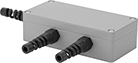 |
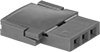
Junction Boxes bring multiple sensors together to create a single system. They’re often used in platform or hopper scales when multiple sensors need to work together to give a total weight reading.
Configurable Tension and Compression Force Sensors
Round
 |  |
Button | Threaded Through Hole |
 |  |
Threaded Standoff | Threaded Stud |
 | |
Dual-Sided Threaded Stud |
Round sensors have a low profile to fit in tight-clearance spaces.
Threaded Stud—Those with a threaded stud screw into equipment.
Threaded Through Hole—Those with a threaded through hole are also known as pancake load cells. They can be bolted to surfaces in any orientation and are commonly used to measure clamping forces. They can be mounted in any orientation.
Button—Those with a button are often used to measure weight in packaging machinery and for pressure sensing in medical device prototypes. Those without mounting holes are about as thin as a credit card. To mount, sandwich them between two plates or use a thin layer of adhesive. They can only be used for compression applications.
Dual-Sided Threaded Stud—Those with a dual-sided threaded stud can monitor push-pull forces. For example, they might be used to test the durability of products that repeatedly fold and unfold.
Threaded Standoff—Those with a threaded standoff have a threaded hole to connect to eye bolts, rod ends, and threaded rods. They’re commonly mounted upside-down between a tank and a leveling mount to weigh material in small tanks and silos.
IP66 Enclosure Rating—IP66 sensors stand up to spraying water.
Enclosure Rating—IP-rated sensors seal out dust.
Load Connection | Mounting Holes | |||||||||||||||||
|---|---|---|---|---|---|---|---|---|---|---|---|---|---|---|---|---|---|---|
Wt. Cap. | Accuracy | Wt. Measuring Increments | Thread Size | Stud Lg. | Dia. | Ht. | Sensor Material | Temp. Range, ° F | Location | Fasteners Included | No. of | Diameter, mm | Thread Size | Enclosure Rating | Each | |||
Measures Tension and Compression | ||||||||||||||||||
With 1 Threaded Stud | ||||||||||||||||||
| 110 lb.; 50 kg | ±8.8 oz., ±250 g | 0.01 lb., 0.001 kg | M12 × 1.75 mm | 1" | 2" | 2" | Alloy Steel | 0 to 140 | Bottom | No | 4 | — | M5 × 0.8 mm | IP66 | 3487N194 | 0000000 | ||
| 220 lb.; 100 kg | ±1.1 lb., ±500 g | 0.01 lb., 0.01 kg | M12 × 1.75 mm | 1" | 2" | 2" | Alloy Steel | 0 to 140 | Bottom | No | 4 | — | M5 × 0.8 mm | IP66 | 3487N195 | 000000 | ||
| 440 lb.; 200 kg | ±2.2 lb., ±1 kg | 0.01 lb., 0.01 kg | M12 × 1.75 mm | 1" | 2" | 2" | Alloy Steel | 0 to 140 | Bottom | No | 4 | — | M5 × 0.8 mm | IP66 | 3487N196 | 000000 | ||
With 1 Threaded Through Hole | ||||||||||||||||||
| 1,100 lb.; 500 kg | ±8.8 oz., ±250 g | 0.1 lb., 0.01 kg | M10 × 1.5 mm | — | 2 15/16" | 1" | Alloy Steel | 0 to 140 | Top | No | 6 | 6.5 | — | — | 3487N223 | 000000 | ||
| 2,200 lb.; 1,000 kg | ±1.1 lb., ±500 g | 0.1 lb., 0.01 kg | M12 × 1.75 mm | — | 3 9/16" | 1" | Alloy Steel | 0 to 140 | Top | No | 6 | 8.5 | — | — | 3487N224 | 000000 | ||
| 5,510 lb.; 2,500 kg | ±2.8 lb., ±1.25 kg | 0.1 lb., 0.1 kg | M12 × 1.75 mm | — | 3 9/16" | 1" | Alloy Steel | 0 to 140 | Top | No | 6 | 8.5 | — | — | 3487N225 | 000000 | ||
| 11,020 lb.; 5,000 kg | ±5.5 lb., ±2.5 kg | 1 lb., 0.1 kg | M24 × 3 mm | — | 5 1/2" | 1 3/4" | Alloy Steel | 0 to 140 | Top | No | 8 | 11 | — | — | 3487N226 | 000000 | ||
With 2 Dual-Sided Threaded Studs | ||||||||||||||||||
| 2.2 lb.; 1 kg | ±0.35 oz., ±10 g | 0.001 oz., 0.1 g | M3 × 0.5 mm | 5/16" | 1" | 1 1/4" | Alloy Steel | 0 to 140 | — | — | — | — | — | — | 3487N452 | 000000 | ||
| 4.4 lb.; 2 kg | ±0.7 oz., ±20 g | 0.001 oz., 0.1 g | M3 × 0.5 mm | 5/16" | 1" | 1 1/4" | Alloy Steel | 0 to 140 | — | — | — | — | — | — | 3487N453 | 000000 | ||
| 11 lb.; 5 kg | ±1.8 oz., ±50 g | 0.01 oz., 0.1 g | M5 × 0.8 mm | 5/16" | 1" | 1 7/16" | Alloy Steel | 0 to 140 | — | — | — | — | — | — | 3487N454 | 000000 | ||
| 22 lb.; 10 kg | ±0.35 oz., ±100 g | 0.01 lb., 0.001 kg | M5 × 0.8 mm | 5/16" | 1" | 1 7/16" | Alloy Steel | 0 to 140 | — | — | — | — | — | — | 3487N455 | 000000 | ||
| 220 lb.; 100 kg | ±2.2 lb., ±1 kg | 0.01 lb., 0.001 kg | M6 × 1 mm | 5/16" | 1" | 1 7/16" | Alloy Steel | 0 to 140 | — | — | — | — | — | — | 3487N456 | 000000 | ||
With 2 Threaded Standoffs | ||||||||||||||||||
| 25,000 lb.; 11,335 kg | ±12.5 lb., ±5.7 kg | 1 lb., 1 kg | 3/4"-16 | — | 4 3/4" | 3 1/16" | Alloy Steel | -40 to 175 | — | — | — | — | — | — | 3487N519 | 000000 | ||
Measures Compression Not Legal-for-Trade | ||||||||||||||||||
With 1 Button | ||||||||||||||||||
| 4.4 lb.; 2 kg | ±0.7 oz., ±20 g | 0.1 lb., 0.01 kg | — | — | 1/2" | 1/4" | Alloy Steel | 0 to 140 | — | — | — | — | — | — | 3487N446 | 000000 | ||
| 22 lb.; 10 kg | ±3.5 oz., ±100 g | 0.1 lb., 0.1 kg | — | — | 1/2" | 1/4" | Alloy Steel | 0 to 140 | — | — | — | — | — | — | 3487N447 | 000000 | ||
| 55 lb.; 25 kg | ±0.44 oz., ±12.5 g | 0.01 lb., 0.01 kg | — | — | 2 1/16" | 7/8" | Alloy Steel | 0 to 140 | Bottom | No | 4 | — | M5 × 0.8 mm | IP66 | 3487N176 | 000000 | ||
| 110 lb.; 50 kg | ±0.88 oz., ±25 g | 0.01 lb., 0.001 kg | — | — | 2 1/16" | 7/8" | Alloy Steel | 0 to 140 | Bottom | No | 4 | — | M5 × 0.8 mm | IP66 | 3487N177 | 000000 | ||
| 220 lb.; 100 kg | ±1.8 oz., ±50 g | 0.01 lb., 0.01 kg | — | — | 2 1/16" | 7/8" | Alloy Steel | 0 to 140 | Bottom | No | 4 | — | M5 × 0.8 mm | IP66 | 3487N178 | 000000 | ||
| 550 lb.; 250 kg | ±4.4 oz., ±125 g | 0.01 lb., 0.01 kg | — | — | 2 1/16" | 7/8" | Alloy Steel | 0 to 140 | Bottom | No | 4 | — | M5 × 0.8 mm | IP66 | 3487N179 | 000000 | ||
| 1,100 lb.; 500 kg | ±8.8 oz., ±250 g | 0.1 lb., 0.01 kg | — | — | 2 1/16" | 7/8" | Alloy Steel | 0 to 140 | Bottom | No | 4 | — | M5 × 0.8 mm | IP66 | 3487N18 | 000000 | ||
| 2,200 lb.; 1,000 kg | ±1.1 lb., ±500 g | 0.1 lb., 0.01 kg | — | — | 2 1/16" | 7/8" | Alloy Steel | 0 to 140 | Bottom | No | 4 | — | M5 × 0.8 mm | IP66 | 3487N181 | 000000 | ||
| 4,405 lb.; 2,000 kg | ±2.2 lb., ±1 kg | 0.1 lb., 0.1 kg | — | — | 3 1/4" | 1 3/4" | Alloy Steel | 0 to 140 | Bottom | No | 3 | — | M8 × 1.25 mm | IP66 | 3487N517 | 000000 | ||
| 11,020 lb.; 5,000 kg | ±5.5 lb., ±2.5 kg | 1 lb., 0.1 kg | — | — | 3 1/4" | 1 3/4" | Alloy Steel | 0 to 140 | Bottom | No | 3 | — | M8 × 1.25 mm | IP66 | 3487N518 | 000000 | ||
|
Connection hubs combine the measurements of multiple tension and compression force sensors together.
Ready-to-Use Tension and Compression Force Sensor Kits
Round
 |  |
PC Connection Kit | PLC Connection Kit |
 | |
Wireless PC Connection Kit |
| |  |
Button | Threaded Through Hole | Threaded Standoff |
 | | |
Dual-Sided Threaded Standoff | Threaded Stud | Dual-Sided Threaded Stud |
Load Connection | PC Connection Kits | PLC Connection Kits | PLC/PC Connection Kits | Wireless PC Connection Kits | ||||||||||||||
|---|---|---|---|---|---|---|---|---|---|---|---|---|---|---|---|---|---|---|
Wt. Cap. | Accuracy | Wt. Measuring Increments | Thread Size | Stud Lg. | Dia. | Ht. | Sensor Material | Temp. Range, ° F | Each | Each | Each | Each | ||||||
Measures Compression and Tension (Not Legal-for-Trade) | ||||||||||||||||||
With 1 Threaded Through Hole | ||||||||||||||||||
| 550 lb.; 250 kg | ±4.4 oz., ±125 g | 0.01 lb., 0.01 kg | M10 × 1.5 mm | — | 2 15/16" | 1" | Alloy Steel | 0 to 140 | 3487N237 | 000000000 | 3487N252 | 000000000 | ——— | 0 | 6384N37 | 000000000 | ||
| 1,100 lb.; 500 kg | ±8.8 oz., ±250 g | 0.1 lb., 0.01 kg | M10 × 1.5 mm | — | 2 15/16" | 1" | Alloy Steel | 0 to 140 | 3487N238 | 00000000 | 3487N253 | 00000000 | ——— | 0 | 6384N39 | 00000000 | ||
| 2,200 lb.; 1,000 kg | ±1.1 lb., ±500 g | 0.1 lb., 0.01 kg | M12 × 1.75 mm | — | 3 9/16" | 1" | Alloy Steel | 0 to 140 | 3487N239 | 00000000 | 3487N254 | 00000000 | ——— | 0 | 6384N35 | 00000000 | ||
| 5,510 lb.; 2,500 kg | ±2.8 lb., ±1.25 kg | 0.1 lb., 0.1 kg | M12 × 1.75 mm | — | 3 9/16" | 1" | Alloy Steel | 0 to 140 | 3487N24 | 00000000 | 3487N255 | 00000000 | ——— | 0 | 6384N38 | 00000000 | ||
| 11,020 lb.; 5,000 kg | ±5.5 lb., ±2.5 kg | 1 lb., 0.1 kg | M24 × 3 mm | — | 5 1/2" | 1 3/4" | Alloy Steel | 0 to 140 | 3487N241 | 00000000 | 3487N256 | 00000000 | ——— | 0 | 6384N36 | 00000000 | ||
With 2 Dual-Sided Threaded Standoffs | ||||||||||||||||||
| 50 lb.; 22 kg | ±1.2 oz., ±33 g | 0.1 lb., 0.01 kg | 1/2"-20 | — | 3 1/4" | 2 3/16" | 17-4 PH Stainless Steel | 70 to 85 | ——— | 0 | ——— | 0 | 3487N138 | 000000000 | ——— | 0 | ||
| 250 lb.; 113 kg | ±6 oz., ±170 g | 0.01 lb., 0.1 kg | 1/2"-20 | — | 3 1/4" | 2 3/16" | 17-4 PH Stainless Steel | 70 to 85 | ——— | 0 | ——— | 0 | 3487N14 | 00000000 | ——— | 0 | ||
| 1,000 lb.; 450 kg | ±2.5 lb., ±1.13 kg | 0.1 lb., 0.01 kg | 1/2"-20 | — | 3 1/4" | 2 3/16" | 17-4 PH Stainless Steel | 70 to 85 | ——— | 0 | ——— | 0 | 3487N142 | 00000000 | ——— | 0 | ||
| 2,500 lb.; 1,130 kg | ±25 lb., ±11.3 kg | 1 lb., 1 kg | 1/2"-20 | — | 3 1/4" | 2 3/16" | 17-4 PH Stainless Steel | 70 to 85 | ——— | 0 | ——— | 0 | 3487N143 | 00000000 | ——— | 0 | ||
With 2 Dual-Sided Threaded Studs | ||||||||||||||||||
| 2.2 lb.; 1 kg | ±0.35 oz., ±10 g | 0.001 oz., 0.1 g | M3 × 0.5 mm | 5/16" | 1" | 1 1/4" | Alloy Steel | 0 to 140 | 3487N467 | 00000000 | 3487N482 | 00000000 | ——— | 0 | ——— | 0 | ||
| 4.4 lb.; 2 kg | ±0.7 oz., ±20 g | 0.001 oz., 0.1 g | M3 × 0.5 mm | 5/16" | 1" | 1 1/4" | Alloy Steel | 0 to 140 | 3487N468 | 00000000 | 3487N483 | 00000000 | ——— | 0 | ——— | 0 | ||
| 11 lb.; 5 kg | ±1.8 oz., ±50 g | 0.01 oz., 0.1 g | M5 × 0.8 mm | 5/16" | 1" | 1 7/16" | Alloy Steel | 0 to 140 | 3487N469 | 00000000 | 3487N484 | 00000000 | ——— | 0 | ——— | 0 | ||
| 22 lb.; 10 kg | ±3.5 oz., ±100 g | 0.01 lb., 1 kg | M5 × 0.8 mm | 5/16" | 1" | 1 7/16" | Alloy Steel | 0 to 140 | 3487N47 | 00000000 | 3487N485 | 00000000 | ——— | 0 | ——— | 0 | ||
| 100 lb.; 45 kg | ±8 oz., ±225 g | 0.1 lb., 1 kg | 1/4"-28 | 1/2" | 1 1/4" | 1 13/16" | 17-4 PH Stainless Steel | 70 to 85 | 3487N162 | 00000000 | ——— | 0 | ——— | 0 | ——— | 0 | ||
| 220 lb.; 100 kg | ±2.2 lb., ±1 kg | 0.01 lb., 1 kg | M6 × 1 mm | 5/16" | 1" | 1 7/16" | Alloy Steel | 0 to 140 | 3487N471 | 00000000 | 3487N486 | 00000000 | ——— | 0 | 6384N34 | 00000000 | ||
With 2 Threaded Standoffs | ||||||||||||||||||
| 25,000 lb.; 11,335 kg | ±12.5 lb., ±5.7 kg | 1 lb., 1 kg | 3/4"-16 | — | 4 3/4" | 3 1/16" | Alloy Steel | -40 to 175 | 6384N43 | 00000000 | ——— | 0 | ——— | 0 | ——— | 0 | ||
Measures Compression, and Tension—IP66 Rated (Not Legal-for-Trade) | ||||||||||||||||||
With 1 Threaded Stud | ||||||||||||||||||
| 110 lb.; 50 kg | ±8.8 oz., ±250 g | 0.01 lb., 1 kg | M12 × 1.75 mm | 1" | 2" | 2" | Alloy Steel | 0 to 140 | 3487N206 | 00000000 | 3487N218 | 00000000 | ——— | 0 | ——— | 0 | ||
| 220 lb.; 100 kg | ±1.1 lb., ±500 g | 0.01 lb., 0.01 kg | M12 × 1.75 mm | 1" | 2" | 2" | Alloy Steel | 0 to 140 | 3487N207 | 00000000 | 3487N219 | 00000000 | ——— | 0 | ——— | 0 | ||
| 440 lb.; 200 kg | ±2.2 lb., ±1 kg | 0.01 lb., 0.01 kg | M12 × 1.75 mm | 1" | 2" | 2" | Alloy Steel | 0 to 140 | 3487N208 | 00000000 | 3487N22 | 00000000 | ——— | 0 | ——— | 0 | ||
| 1,100 lb.; 500 kg | ±5.5 lb., ±2.5 kg | 0.01 lb., 0.01 kg | M12 × 1.75 mm | 1" | 2" | 2" | Alloy Steel | 0 to 140 | 3487N209 | 00000000 | 3487N221 | 00000000 | ——— | 0 | ——— | 0 | ||
Measures Compression (Not Legal-for-Trade) | ||||||||||||||||||
With 1 Button | ||||||||||||||||||
| 4.4 lb.; 2 kg | ±0.7 oz., ±20 g | 0.1 lb., 0.01 kg | — | — | 1/2" | 1/4" | Alloy Steel | 0 to 140 | 3487N448 | 00000000 | 3487N45 | 000000 | ——— | 0 | ——— | 0 | ||
| 10 lb.; 4.5 kg | ±0.8 oz., ±23 g | 0.001 lb., 1 kg | — | — | 1 1/4" | 13/32" | 17-4 PH Stainless Steel | 70 to 85 | 3487N144 | 000000 | ——— | 0 | ——— | 0 | ——— | 0 | ||
| 22 lb.; 10 kg | ±3.5 oz., ±100 g | 0.1 lb., 0.1 kg | — | — | 1/2" | 1/4" | Alloy Steel | 0 to 140 | 3487N449 | 00000000 | 3487N451 | 000000 | ——— | 0 | ——— | 0 | ||
| 100 lb.; 45 kg | ±8 oz., ±225 g | 0.1 lb., 1 kg | — | — | 1 1/4" | 13/32" | 17-4 PH Stainless Steel | 70 to 85 | 3487N146 | 000000 | ——— | 0 | ——— | 0 | ——— | 0 | ||
| 200 lb.; 90 kg | ±1 lb., ±450 g | 1 lb., 0.01 kg | — | — | 1 1/4" | 13/32" | 17-4 PH Stainless Steel | 70 to 85 | 3487N147 | 000000 | ——— | 0 | ——— | 0 | ——— | 0 | ||
With 1 Threaded Standoff | ||||||||||||||||||
| 50 lb.; 22 kg | ±1.2 oz., ±33 g | 0.1 lb., 0.01 kg | 1/2"-20 | — | 3 1/4" | 1 3/16" | 17-4 PH Stainless Steel | 70 to 85 | 3487N108 | 000000 | ——— | 0 | ——— | 0 | ——— | 0 | ||
| 100 lb.; 45 kg | ±2.4 oz., ±68 g | 0.01 lb., 1 kg | 1/2"-20 | — | 3 1/4" | 1 3/16" | 17-4 PH Stainless Steel | 70 to 85 | 3487N109 | 000000 | ——— | 0 | ——— | 0 | ——— | 0 | ||
| 250 lb.; 113 kg | ±6 oz., ±170 g | 0.01 lb., 0.1 kg | 1/2"-20 | — | 3 1/4" | 1 3/16" | 17-4 PH Stainless Steel | 70 to 85 | 3487N11 | 000000 | ——— | 0 | ——— | 0 | ——— | 0 | ||
| 500 lb.; 225 kg | ±12 oz., ±338 g | 0.01 lb., 0.1 kg | 1/2"-20 | — | 3 1/4" | 1 3/16" | 17-4 PH Stainless Steel | 70 to 85 | 3487N111 | 000000 | ——— | 0 | ——— | 0 | ——— | 0 | ||
| 1,000 lb.; 450 kg | ±2.5 lb., ±1.13 kg | 0.1 lb., 0.01 kg | 1/2"-20 | — | 3 1/4" | 1 3/16" | 17-4 PH Stainless Steel | 70 to 85 | 3487N112 | 000000 | ——— | 0 | ——— | 0 | ——— | 0 | ||
| 2,500 lb.; 1,130 kg | ±25 lb., ±11.3 kg | 1 lb., 1 kg | 1/2"-20 | — | 3 1/4" | 1 3/16" | 17-4 PH Stainless Steel | 70 to 85 | 3487N113 | 000000 | ——— | 0 | ——— | 0 | ——— | 0 | ||
With 1 Threaded Stud | ||||||||||||||||||
| 50 lb.; 22 kg | ±4 oz., ±110 g | 0.1 lb., 0.01 kg | 10-32 | 1/2" | 1 1/4" | 13/16" | 17-4 PH Stainless Steel | 70 to 85 | 3487N153 | 000000 | ——— | 0 | ——— | 0 | ——— | 0 | ||
With 1 Threaded Through Hole | ||||||||||||||||||
| 1,100 lb.; 500 kg | ±8.8 oz., ±250 g | 0.1 lb., 0.01 kg | M10 × 1.5 mm | — | 2 15/16" | 1" | Alloy Steel | 0 to 140 | 3487N228 | 00000000 | 3487N243 | 000000 | ——— | 0 | ——— | 0 | ||
| 2,200 lb.; 1,000 kg | ±1.1 lb., ±500 g | 0.1 lb., 0.01 kg | M12 × 1.75 mm | — | 3 9/16" | 1" | Alloy Steel | 0 to 140 | 3487N229 | 00000000 | 3487N244 | 000000 | ——— | 0 | ——— | 0 | ||
| 5,510 lb.; 2,500 kg | ±2.8 lb., ±1.25 kg | 0.1 lb., 0.1 kg | M12 × 1.75 mm | — | 3 9/16" | 1" | Alloy Steel | 0 to 140 | 3487N23 | 00000000 | 3487N245 | 000000 | ——— | 0 | ——— | 0 | ||
| 11,020 lb.; 5,000 kg | ±5.5 lb., ±2.5 kg | 1 lb., 0.1 kg | M24 × 3 mm | — | 5 1/2" | 1 3/4" | Alloy Steel | 0 to 140 | 3487N231 | 00000000 | 3487N246 | 000000 | ——— | 0 | 6384N31 | 00000000 | ||
With 2 Dual-Sided Threaded Studs | ||||||||||||||||||
| 2.2 lb.; 1 kg | ±0.35 oz., ±10 g | 0.001 oz., 0.1 g | M3 × 0.5 mm | 5/16" | 1" | 1 1/4" | Alloy Steel | 0 to 140 | 3487N457 | 00000000 | ——— | 0 | ——— | 0 | ——— | 0 | ||
| 4.4 lb.; 2 kg | ±0.7 oz., ±20 g | 0.001 oz., 0.1 g | M3 × 0.5 mm | 5/16" | 1" | 1 1/4" | Alloy Steel | 0 to 140 | 3487N458 | 00000000 | ——— | 0 | ——— | 0 | ——— | 0 | ||
| 220 lb.; 100 kg | ±2.2 lb., ±1 kg | 0.01 lb., 1 kg | M6 × 1 mm | 5/16" | 1" | 1 7/16" | Alloy Steel | 0 to 140 | 3487N461 | 00000000 | ——— | 0 | ——— | 0 | ——— | 0 | ||
With 2 Threaded Standoffs | ||||||||||||||||||
| 25,000 lb.; 11,335 kg | ±12.5 lb., ±5.7 kg | 1 lb., 1 kg | 3/4"-16 | — | 4 3/4" | 3 1/16" | Alloy Steel | -40 to 175 | 6384N42 | 00000000 | ——— | 0 | ——— | 0 | ——— | 0 | ||
Measures Compression—IP66 Rated (Not Legal-for-Trade) | ||||||||||||||||||
With 1 Button | ||||||||||||||||||
| 55 lb.; 25 kg | ±0.44 oz., ±12.5 g | 0.01 lb., 0.01 kg | — | — | 2 1/16" | 7/8" | Alloy Steel | 0 to 140 | 3487N182 | 000000 | 3487N188 | 000000 | ——— | 0 | ——— | 0 | ||
| 110 lb.; 50 kg | ±0.88 oz., ±25 g | 0.01 lb., 1 kg | — | — | 2 1/16" | 7/8" | Alloy Steel | 0 to 140 | 3487N183 | 000000 | 3487N189 | 000000 | ——— | 0 | ——— | 0 | ||
| 220 lb.; 100 kg | ±1.8 oz., ±50 g | 0.01 lb., 0.01 kg | — | — | 2 1/16" | 7/8" | Alloy Steel | 0 to 140 | ——— | 0 | 3487N19 | 000000 | ——— | 0 | ——— | 0 | ||
| 550 lb.; 250 kg | ±4.4 oz., ±125 g | 0.01 lb., 0.01 kg | — | — | 2 1/16" | 7/8" | Alloy Steel | 0 to 140 | 3487N185 | 000000 | 3487N191 | 000000 | ——— | 0 | 6384N25 | 00000000 | ||
| 1,100 lb.; 500 kg | ±8.8 oz., ±250 g | 0.1 lb., 0.01 kg | — | — | 2 1/16" | 7/8" | Alloy Steel | 0 to 140 | 3487N186 | 000000 | 3487N192 | 000000 | ——— | 0 | 6384N26 | 00000000 | ||
| 2,200 lb.; 1,000 kg | ±1.1 lb., ±500 g | 0.1 lb., 0.01 kg | — | — | 2 1/16" | 7/8" | Alloy Steel | 0 to 140 | 3487N187 | 000000 | 3487N193 | 000000 | ——— | 0 | 6384N24 | 00000000 | ||
| 4,405 lb.; 2,000 kg | ±2.2 lb., ±1 kg | 0.1 lb., 0.1 kg | — | — | 3 1/4" | 1 3/4" | Alloy Steel | 0 to 140 | 6384N17 | 00000000 | ——— | 0 | ——— | 0 | 6384N28 | 00000000 | ||
| 11,020 lb.; 5,000 kg | ±5.5 lb., ±2.5 kg | 1 lb., 0.1 kg | — | — | 3 1/4" | 1 3/4" | Alloy Steel | 0 to 140 | 6384N18 | 00000000 | ——— | 0 | ——— | 0 | 6384N29 | 00000000 | ||
Measures Tension (Not Legal-for-Trade) | ||||||||||||||||||
With 1 Threaded Stud | ||||||||||||||||||
| 50 lb.; 22 kg | ±4 oz., ±110 g | 0.1 lb., 0.01 kg | 10-32 | 1/2" | 1 1/4" | 13/16" | 17-4 PH Stainless Steel | 70 to 85 | ——— | 0 | ——— | 0 | 3487N169 | 00000000 | ——— | 0 | ||
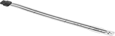
Compression Force Sensors for Tight Spaces
Sensors
 |
Round Sensor |
2-Pin Connection | 3-Pin Connection |
Tab Connection |
 | 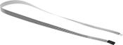 |
Adapter | Extension Cable |
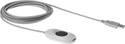
Expand your connection kit with additional sensors. Using more than one sensor allows you to monitor pressure at multiple points across a machine. Each sensor requires its own hub. Track changes in resistance by adding a multimeter, or use the data recording software included in our kits (sold separately).
Additional sensors and hubs expand the connections kits.
2-Pin Sensor Connection and 3-Pin Sensor Connection—To connect 3-pin and 2-pin sensors into hubs with USB connections, adapters (sold separately) are required
Extension Cables—Adapters are required to connect 3-pin and 2-pin sensors into hubs with a USB connection.
Load Cells | Extension Cables | ||||||||||||||||
|---|---|---|---|---|---|---|---|---|---|---|---|---|---|---|---|---|---|
Measuring Increments | |||||||||||||||||
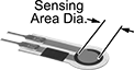
Wt. Cap., lb. | Force Cap., N | Accuracy | Weight, lb. | Force, N | Wd., mm | Thk., mm | Sensing Area Dia., mm | Max. Current, mA | Input Voltage Range, V DC | Temp. Range, ° F | Choose a Length, mm | Each | Each | ||||
Round—Tab Sensor Connection | |||||||||||||||||
| 1 | 4 | ±3% | 0.1 | 0.01 | 14 | 0.203 | 9.53 | 2.5 | 0.25 to 1.25 | -40 to 140 | 229 | 3692N31 | 000000 | ——— | 0 | ||
| 25 | 111 | ±3% | 0.1 | 0.01 | 14 | 0.203 | 9.53 | 2.5 | 0.25 to 1.25 | -40 to 140 | 229 | 3692N32 | 00000 | ——— | 0 | ||
| 150 | 667 | ±3% | 0.1 | 0.01 | 14 | 0.203 | 9.53 | 2.5 | 0.25 to 1.25 | -40 to 140 | 229 | 3692N33 | 00000 | ——— | 0 | ||
Round—2-Pin Sensor Connection | |||||||||||||||||
| 1 | 4 | ±3% | 0.1 | 0.01 | 14 | 0.203 | 9.53 | 2.5 | 0.25 to 1.25 | -40 to 185 | 25 | 3692N37 | 00000 | 3692N51 | 000000 | ||
| 4 | 18 | ±3% | 0.1 | 0.01 | 7.6 | 0.203 | 3.8 | 2.5 | 0.25 to 1.25 | -40 to 140 | 16 | 3692N11 | 00000 | ——— | 0 | ||
| 25 | 111 | ±3% | 0.1 | 0.01 | 14 | 0.203 | 9.53 | 2.5 | 0.25 to 1.25 | -40 to 140 | 25 | 3692N26 | 00000 | 3692N51 | 00000 | ||
| 25 | 111 | ±3% | 0.1 | 0.01 | 31.8 | 0.203 | 25.4 | 2.5 | 0.25 to 1.25 | -40 to 140 | 25 | 3692N28 | 00000 | 3692N51 | 00000 | ||
| 100 | 445 | ±3% | 0.1 | 0.01 | 14 | 0.203 | 9.53 | 2.5 | 0.25 to 1.25 | -40 to 140 | 25 | 3692N27 | 00000 | 3692N51 | 00000 | ||
Round—3-Pin Sensor Connection | |||||||||||||||||
| 1 | 4 | ±3% | 0.1 | 0.01 | 14 | 0.203 | 9.53 | 2.5 | 0.25 to 1.25 | -40 to 140 | 51, 191 | 3692N1 | 00000 | 3692N51 | 00000 | ||
| 25 | 111 | ±3% | 0.1 | 0.01 | 14 | 0.203 | 9.53 | 2.5 | 0.25 to 1.25 | -40 to 140 | 51, 191 | 3692N2 | 00000 | 3692N51 | 00000 | ||
| 100 | 445 | ±3% | 0.1 | 0.01 | 14 | 0.203 | 9.53 | 2.5 | 0.25 to 1.25 | -40 to 140 | 51, 191 | 3692N3 | 00000 | 3692N51 | 00000 | ||
| 150 | 667 | ±3% | 0.1 | 0.01 | 14 | 0.203 | 9.53 | 2.5 | 0.25 to 1.25 | -40 to 140 | 191 | 3692N36 | 00000 | 3692N51 | 00000 | ||
Torque Sensors
 |
Measure and record manually applied torque. These sensors convert torque into an electrical signal that your computer or programmable logic controller (PLC) can read.
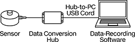
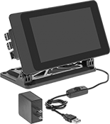
PC Connection Kits—Sensors with a PC connection kit include software that plots and analyzes measurements, so you can track highs, lows, and averages over time. If measurements fall outside a certain range, the software can also set off alarms or send you an email. Export your data to Excel, MATLAB, LabVIEW, and other programs for analysis. Connect to a computer or tablet with the included USB cord.
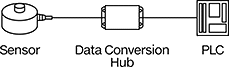
PLC Connection Kits—Sensors with a PLC connection kit send signals to a PLC to trigger actions in your system, such as checking for proper fastening between joints or connections. They can also trigger robotic arms and other machinery to apply a precise amount of force.
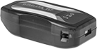
Wireless PC Connection Kits—Sensors with a wireless PC connection kit also have a built-in transmitter that uses Wi-Fi to send signals to a USB receiver plugged into your PC.
Accuracy | Sensors | PC Connection Kits | PLC Connection Kits | Wireless PC Connection Kits | ||||||||||||
|---|---|---|---|---|---|---|---|---|---|---|---|---|---|---|---|---|
Torque Range, N-m | N Torque Measuring Increments, N-m | Torque-Measuring Direction | Counterclockwise | Clockwise | Dia. | Ht. | Sensor Material | Each | Each | Each | Each | |||||
| 0.1 to 6 | 0.01 | Clockwise and Counterclockwise | ±1% | ±1% | 1 1/2" | 2" | Aluminum | 7570N11 | 0000000 | 7570N15 | 000000000 | 7570N19 | 000000000 | 7570N24 | 000000000 | |
| 0.1 to 10 | 0.01 | Clockwise and Counterclockwise | ±1% | ±1% | 1 1/2" | 2" | Aluminum | 7570N12 | 000000 | 7570N16 | 00000000 | 7570N21 | 00000000 | 7570N25 | 00000000 | |
| 0.1 to 60 | 0.06 | Clockwise and Counterclockwise | ±1% | ±1% | 1 1/2" | 2" | Aluminum | 7570N13 | 000000 | 7570N17 | 00000000 | 7570N22 | 00000000 | 7570N26 | 00000000 | |
| 0.1 to 150 | 0.15 | Clockwise and Counterclockwise | ±1% | ±1% | 1 1/2" | 2" | Aluminum | 7570N14 | 000000 | 7570N18 | 00000000 | 7570N23 | 00000000 | 7570N27 | 00000000 | |


