Filter by


Input Voltage
For Use With
Switch Starting Position
Export Control Classification Number (ECCN)
Electrical Connection

DFARS Specialty Metals
Housing Material
Specifications Met
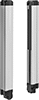
Light Beam Height
Length
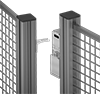
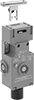
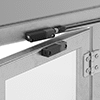
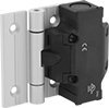
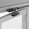
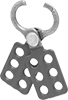
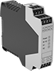
Safety Switches

 Abrading & Polishing
 Building & Grounds
 Electrical & Lighting
 Fabricating
 Fastening & Joining
 Filtering
 Flow & Level Control
 Furniture & Storage
 Hand Tools
 Hardware
 Heating & Cooling
 Lubricating
 Material Handling
 Measuring & Inspecting
 Office Supplies & Signs
 Pipe, Tubing, Hose & Fittings
 Plumbing and Janitorial
 Power Transmission
 Pressure & Temperate Control
 Pulling & Lifting
 Raw Materials
 Safety Supplies
 Sawing & Cutting
 Sealing
 Shipping
 Suspending