



























Filter by
Product Family
Mount Type

Length


ID

Height
Weight Capacity


Movement

Anchor Point Type

Export Control Classification Number (ECCN)

DFARS Specialty Metals
Load Securement Type
Quick-Release Magnetic Brackets
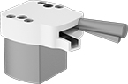 | 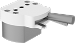 | 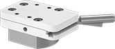 |
150 lbf Maximum Pull | 235 lbf Maximum Pull | 245 lbf Maximum Pull |
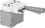 | 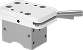 | |
400 lbf Maximum Pull | 600 lbf Maximum Pull |
Plate | Base | Mounting | |||||||||||||||
|---|---|---|---|---|---|---|---|---|---|---|---|---|---|---|---|---|---|
Max. Pull, lbf | Lg. | Wd. | Ht. | Lg. | Wd. | Ht. | Handle Lg. | Case Material | Fasteners Included | Hole Thread Size | Hole Ctr.-to-Ctr. Lg. | Hole Ctr.-to-Ctr. Wd. | Mounting Hole Depth (Number of Holes) | Each | |||
| 150 | 2" | 1 3/4" | 5/8" | 1 1/4" | 1 9/16" | 15/16" | 1 5/16" | Steel | No | M6 | 1 3/16" | — | 3/8" (2) | 2290N11 | 0000000 | ||
| 235 | 2 9/16" | 2 3/8" | 11/16" | 1 5/8" | 2 3/16" | 1 1/16" | 1 1/2" | Steel | No | M6 | 9/16" | — | 5/16" (2); 1/4" (1) | 2290N12 | 000000 | ||
| 245 | 3 15/16" | 2 1/2" | 7/8" | 2 13/16" | 2" | 7/8" | 2" | Steel | No | M6 | 7/8" | 1 13/16" | 3/8" (4) | 2290N14 | 000000 | ||
| 400 | 2 9/16" | 2 3/8" | 11/16" | 1 5/8" | 2 1/2" | 1 7/8" | 2 3/8" | Steel | No | M6 | 9/16" | — | 5/16" (3) | 2290N13 | 000000 | ||
| 600 | 3 15/16" | 2 1/2" | 7/8" | 2 15/16" | 2" | 1 15/16" | 2" | Steel | No | M6 | 7/8" | 1 13/16" | 3/8" (4) | 2290N15 | 000000 | ||
Magnetic Vibration-Damping Strap Routing Clamps
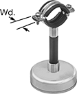 | 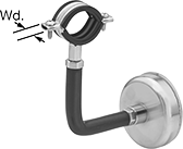 |
Straight | 90° Angle |
ID | ||||||||||
|---|---|---|---|---|---|---|---|---|---|---|
Inch | Metric, mm | Wt. Cap., lb. | Lg. | Wd. | Ht. | Magnet Base Dia. | Each | |||
Zinc-Plated Steel | ||||||||||
Straight Bracket | ||||||||||
| 9/16" to 3/4" | 14 to 19 | 75 | 2 1/2" | 13/16" | 2 3/8" | 2 1/2" | 2902N11 | 000000 | ||
| 9/16" to 3/4" | 14 to 19 | 75 | 2 1/2" | 13/16" | 5 1/8" | 2 1/2" | 2902N19 | 00000 | ||
| 9/16" to 3/4" | 14 to 19 | 130 | 2 1/2" | 13/16" | 2 3/4" | 3 1/8" | 2902N15 | 00000 | ||
| 13/16" to 1" | 21 to 25 | 75 | 2 5/8" | 13/16" | 2 9/16" | 2 1/2" | 2902N12 | 00000 | ||
| 13/16" to 1" | 21 to 25 | 75 | 2 5/8" | 13/16" | 5 11/16" | 2 1/2" | 2902N21 | 00000 | ||
| 13/16" to 1" | 21 to 25 | 130 | 2 5/8" | 13/16" | 2 15/16" | 3 1/8" | 2902N16 | 00000 | ||
| 1" to 1 1/4" | 25 to 32 | 75 | 2 3/4" | 13/16" | 2 3/4" | 2 1/2" | 2902N13 | 00000 | ||
| 1" to 1 1/4" | 25 to 32 | 130 | 2 3/4" | 13/16" | 3 1/8" | 3 1/8" | 2902N17 | 00000 | ||
| 1" to 1 1/4" | 25 to 32 | 130 | 2 3/4" | 13/16" | 5 7/8" | 3 1/8" | 2902N22 | 00000 | ||
| 1 1/4" to 1 7/16" | 32 to 37 | 75 | 3" | 13/16" | 2 15/16" | 2 1/2" | 2902N14 | 00000 | ||
| 1 1/4" to 1 7/16" | 32 to 37 | 130 | 3" | 13/16" | 3 3/8" | 3 1/8" | 2902N18 | 00000 | ||
| 1 1/4" to 1 7/16" | 32 to 37 | 130 | 3" | 13/16" | 6 5/16" | 3 1/8" | 2902N23 | 00000 | ||
90° Angle Bracket | ||||||||||
| 9/16" to 3/4" | 14 to 19 | 75 | 6 1/2" | 13/16" | 5 11/16" | 2 1/2" | 2902N24 | 00000 | ||
| 13/16" to 1" | 21 to 25 | 75 | 6 11/16" | 13/16" | 5 7/8" | 2 1/2" | 2902N25 | 00000 | ||
| 1" to 1 1/4" | 25 to 32 | 130 | 8 1/16" | 13/16" | 6 1/2" | 3 1/8" | 2902N26 | 00000 | ||
| 1 1/4" to 1 7/16" | 32 to 37 | 130 | 8 1/4" | 13/16" | 6 7/8" | 3 1/8" | 2902N27 | 00000 | ||
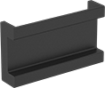
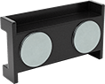
Magnetic-Back DIN Rails
 |
 |
Wt. Cap., lb. | Ht., mm | Lg., mm | Overall Lg., mm | Dp., mm | Material | Color | Flammability Rating | Each | |||
|---|---|---|---|---|---|---|---|---|---|---|---|
DIN 3 | |||||||||||
| 6 1/2 | 35 | 66 | 71 | 15 | Plastic | Black | UL 94 V-0 | 3661N11 | 000000 | ||
Magnetic Tie-Down Rings
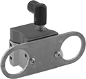 |
Use these rings to create a temporary anchor point on ferrous metal surfaces. Turn the handle to engage the magnet.
Note: Capacity is based on direct contact on a flat, smooth, untreated surface. Variations in mounting surface conditions will reduce capacity.
Warning: Never use for lifting applications.
Ring | Handle | |||||||||||||
|---|---|---|---|---|---|---|---|---|---|---|---|---|---|---|
Wt. Cap., lb. | Inner Wd. | Style | Lg. | Wd. | Overall Ht. | Housing Material | Material | Color | Magnet Type | For Max. Surface Thk. | Each | |||
| 35 | 1/2" | Round Ring | 4 1/8" | 1 13/16" | 2 3/4" | Nickel-Plated Steel | Powder-Coated Aluminum | Black | Rare Earth | 1/4" | 3154T4 | 0000000 | ||
Magnetic Routing Ring Bases

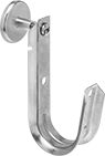
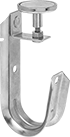
Routing J-Hooks
 |  |
Style D | Style E |
Route bundles of wire and cable through a single hook. A wide opening allows access for installation, adjustment, and removal.
Styles D and E—Style D and style E hooks have magnets for a temporary hold on steel and iron surfaces.
Overall | ||||||||||||
|---|---|---|---|---|---|---|---|---|---|---|---|---|
Style | For Max. Bundle Dia. | Material | Temp. Range, ° F | Wt. Cap., lb. | Lg. | Wd. | Ht. | Certification | Each | |||
Magnetic | ||||||||||||
| D | 3/4" | Galvanized Steel | -40 to 570 | 15 | 1 1/16" | 7/8" | 3 5/8" | UL Listed | 1717T14 | 000000 | ||
| D | 1 5/16" | Galvanized Steel | -40 to 570 | 15 | 2" | 1 3/8" | 4 7/8" | UL Listed | 1717T15 | 00000 | ||
| D | 2" | Galvanized Steel | -40 to 570 | 15 | 2 1/2" | 1 3/8" | 5 3/16" | UL Listed | 1717T16 | 00000 | ||
| E | 3/4" | Galvanized Steel | -40 to 570 | 15 | 1 1/16" | 7/8" | 4 3/4" | UL Listed | 1717T11 | 00000 | ||
| E | 1 5/16" | Galvanized Steel | -40 to 570 | 15 | 2" | 1 3/8" | 4 5/8" | UL Listed | 1717T12 | 00000 | ||
| E | 2" | Galvanized Steel | -40 to 570 | 15 | 2 1/2" | 1 3/8" | 5 1/4" | UL Listed | 1717T13 | 00000 | ||
Cable Holders
 |  |
Style Z | Style AA |
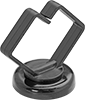
Mount to a surface to secure and route cable.
Magnetic Back
| |
Style Z | Style AA |
Magnetic-back cable holders attach to steel beams, joists, and rails.
Overall | Pkg. | ||||||||||||||||
|---|---|---|---|---|---|---|---|---|---|---|---|---|---|---|---|---|---|
Style | For Max. Bundle Dia. | Holding Cap., lb. | Lg. | Wd. | Ht. | For Use Outdoors | Specs. Met | Flammability Rating | Temp. Range, ° F | Color | Pkg. Qty. | 1-19 | 20-99 | 100-Up | |||
Acetal | |||||||||||||||||
| Z | 1/2" | — | 3/4" | 3/4" | 3/4" | No | CSA C22.2 No. 18.5, UL 1565 | — | -40 to 170 | Off-White | 1 | 7565K114 | 00000 | 00000 | 00000 | ||
| Z | 3/4" | — | 3/4" | 3/4" | 1" | No | CSA C22.2 No. 18.5, UL 1565 | — | -40 to 170 | Off-White | 1 | 7565K113 | 0000 | 0000 | 0000 | ||
| Z | 1" | — | 15/16" | 15/16" | 1 1/4" | No | CSA C22.2 No. 18.5, UL 1565 | — | -40 to 170 | Off-White | 1 | 7565K115 | 0000 | 0000 | 0000 | ||
Polycarbonate | |||||||||||||||||
| Z | 1/2" | 10 | 1/2" | 3/4" | 3/4" | No | UL 62275 Type 21 | UL 2043, UL 94 V-2 | -40 to 170 | Black | 1 | 1228N5 | 0000 | 0000 | 0000 | ||
| Z | 3/4" | 10 | 3/4" | 3/4" | 1" | No | UL 62275 Type 21 | UL 2043, UL 94 V-2 | -40 to 170 | Black | 1 | 1228N3 | 0000 | 0000 | 0000 | ||
| Z | 1" | 10 | 1" | 1" | 1 1/4" | No | UL 62275 Type 21 | UL 2043, UL 94 V-2 | -40 to 170 | Black | 1 | 1228N1 | 0000 | 0000 | 0000 | ||
| AA | 1/2" | 10 | 1" | 1" | 13/16" | No | UL 62275 Type 21 | UL 2043, UL 94 V-2 | -40 to 170 | Black | 1 | 1228N7 | 0000 | 0000 | 0000 | ||
Spring Clamps with Flexible Arm
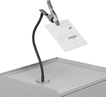 | 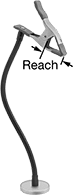 |
Shown with Magnetic Mount | Magnetic Mount |
Opening | Jaw | |||||||||||
|---|---|---|---|---|---|---|---|---|---|---|---|---|
Max. | Min. | Reach Lg. | Holding Cap. | Type | Wd. | Material | Overall Lg. | Mount Type | Each | |||
Steel Body | ||||||||||||
Cushion Grip | ||||||||||||
| 2" | 0" | 2 5/8" | Not Rated | Fixed | 1" | Rubber | 22" | Magnetic | 50855A66 | 000000 | ||
Cable Tie Mounts
 |
Style M |
Mount to a surface and add a cable tie to secure a bundle.
Magnetic Back—Polycarbonate
|
Style M |
Magnetic-back mounts attach to steel beams, joists, and rails.
Any Way—Any-way mounts allow ties to be inserted from opposite sides and have a head that spins to route the cable in any direction.
UL 94 V-2—Mounts that meet UL 94 V-2 stop burning within 30 seconds.
Routing Rings
 |
Magnetic |
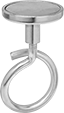
Also known as bridle rings, routing rings have an open-eye design that allows you to quickly install wire and cable.
Magnetic—Magnetic routing rings provide a temporary hold on steel and iron surfaces.
Ball-Grip Positioning Arms
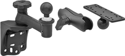 |
Arm Built with Rotating Complete Arm with Ball, Rigid Connector, and Universal Mounting Plate |
Ball-and-socket connections allow 360° positioning. Choose a complete arm or select a base, connectors, and accessories to build your own.
To ensure compatibility, select components that have the same ball diameter. Use reducing connectors (sold separately) to pair components with a 1 1/2" ball diameter to those with a 1" ball diameter.

Hook and Loop Strap Mounts
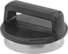 |
Style C |
Add a hook and loop strap to these mounts to secure a bundle.
For Cable Tie | Overall | Black | |||||||||||||
|---|---|---|---|---|---|---|---|---|---|---|---|---|---|---|---|
Style | For Max. No. of Bundles | Holding Cap., lb. | Max. Wd. | Max. Thk. | Dia. | Ht. | Swivel Rotation | For Use Outdoors | Flammability Rating | Temp. Range, ° F | Pkg. Qty. | Pkg. | |||
Magnetic Back—Polycarbonate | |||||||||||||||
Any Way | |||||||||||||||
| C | 1 | 15 | 5/8" | 3/4" | 15/16" | 3/4" | 360° | No | UL 2043 | -40 to 170 | 1 | 1256N2 | 00000 | ||
