


Filter by


Switch Designation

Switch Starting Position
Housing Material
Electrical Connection

Wire Connection

Mount Type

Sensor Type
U.S.–Mexico–Canada Agreement (USMCA) Qualifying
Export Control Classification Number (ECCN)
DFARS Specialty Metals
Magnetically Actuated Switches
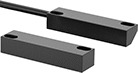 | 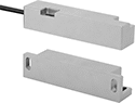 | 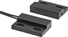 |
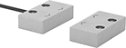
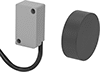
Style A | Style B | Style C |
 |  |  |
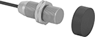
Style E | Style H | Style J |
 | ||
Style K |
 |  |  |
3-Pole M8 Plug | 4-Pole M12 Plug | 6-Pole M12 Plug |
These switches actuate when a magnet comes within sensing distance, and reset when the magnet moves away. They’re often used to detect when a door or window opens. Mount the switch in a stationary position, such as a door frame, and mount the magnet to a movable object, such as the door. They do not include a safety relay and cannot be used with safety-guard doors found on machinery.
M8 Connection and M12 Connection—Switches with a M12 or M8 plug connect to cords with a socket (sold separately), allowing you to quickly connect and disconnect the switch.
LED Status Indicator—Switches with an LED status indicator let you visually confirm that it’s connected and whether it’s actuated.
NEMA 4X Enclosure Rating—NEMA 4X rated switches are protected from corrosion and washdowns.
NEMA 6 Enclosure Rating—NEMA 6 rated switches are protected from temporary submersion.
IP65 Enclosure Rating—IP65 rated switches protect against rinsing and dust.
IP67 Enclosure Rating—IP67 rated switches protect against temporary submersion, as well as dust and dirt.
Switches | Replacement Magnets | |||||||||||||||||||
|---|---|---|---|---|---|---|---|---|---|---|---|---|---|---|---|---|---|---|---|---|
Wire Leads | ||||||||||||||||||||
Style | No. of Circuits Controlled | Switch Starting Position | Switch Designation | Switching Current @ Voltage | Max. Voltage | Max. Sensing Distance | No. of | Lg., ft. | Dia. | Lg. | Wd. | Ht. | Mounting Thread Size | Enclosure Rating | Each | Each | ||||
Plastic Housing with Wire Leads | ||||||||||||||||||||
| A | 1 | 1 Off | SPST-NO | 2 amp @ 30V AC, 2 amp @ 60V DC | 250V AC 250V DC | 0.8" | 2 | 3 | — | 3.16" | 0.79" | 0.59" | — | NEMA 4X, IP67 | 65985K76 | 0000000 | 65985K85 | 000000 | ||
| A | 1 | 1 On | SPST-NC | 2 amp @ 230V AC | 230V AC | 0.47" | 2 | 6 | — | 3" | 1.19" | 0.63" | — | NEMA 6, IP67 | 65985K426 | 000000 | 65985K441 | 000000 | ||
| B | 1 | 1 On | SPST-NC | 1 amp @ 30V DC | 30V DC | 0.47" | 2 | 10 | — | 3.25" | 0.75" | 0.67" | — | NEMA 6, IP67 | 65985K427 | 000000 | 65985K439 | 000000 | ||
| B | 1 | 1 On | SPST-NC | 2 amp @ 230V AC | 230V AC | 0.47" | 2 | 19 | — | 3.25" | 0.75" | 0.67" | — | NEMA 6, IP67 | 65985K421 | 000000 | 65985K439 | 000000 | ||
| B | 2 | 1 Off and 1 On | DPST-1NO/1NC | 1 amp @ 30V DC | 30V DC | 0.47" | 4 | 19 | — | 3.25" | 0.75" | 0.67" | — | NEMA 6, IP67 | 65985K419 | 000000 | 65985K439 | 000000 | ||
| B | 2 | 1 Off and 1 On | DPST-1NO/1NC | 2 amp @ 230V AC | 230V AC | 0.47" | 4 | 19 | — | 3.25" | 0.75" | 0.67" | — | NEMA 6, IP67 | 65985K434 | 000000 | 65985K439 | 000000 | ||
| B | 2 | 2 On | DPST-NC | 1 amp @ 30V DC | 30V DC | 0.47" | 4 | 19 | — | 3.25" | 0.75" | 0.67" | — | NEMA 6, IP67 | 65985K425 | 000000 | 65985K439 | 000000 | ||
| B | 2 | 2 On | DPST-NC | 2 amp @ 230V AC | 230V AC | 0.47" | 4 | 19 | — | 3.25" | 0.75" | 0.67" | — | NEMA 6, IP67 | 65985K429 | 000000 | 65985K439 | 000000 | ||
| C | 1 | 1 Off | SPST-NO | 80 mA @ 120V AC | 250V AC | 0.4" | 2 | 3 | — | 1.13" | 0.71" | 0.25" | — | NEMA 4X, IP67 | 65985K72 | 000000 | 65985K82 | 00000 | ||
| E | 1 | 1 Off | SPST-NO | 80 mA @ 120V AC | 250V AC | 0.1" | 2 | 3 | 0.24" | 1.12" | — | — | — | NEMA 4X, IP67 | 65985K71 | 000000 | 65985K81 | 00000 | ||
| H | 3 | 1 Off and 2 On | 3PST-1NO/2NC | 0.3 amp @ 30V DC | 30V DC | 0.47" | 6 | 16 | — | 2.08" | 1.1" | 0.55" | — | NEMA 6, IP67 | 65985K423 | 000000 | 65985K438 | 00000 | ||
Plastic Housing with Wire Leads and LED Status Indicator | ||||||||||||||||||||
| J | 1 | 1 Off | SPST-NO | 0.2 amp @ 3V DC | 30V DC | 2.36" | 3 | 6 | — | 1.09" | 0.63" | 0.4" | — | IP67 | 65985K502 | 000000 | 65985K408 | 00000 | ||
Plastic Housing with 3-Pole M8 Plug and LED Status Indicator | ||||||||||||||||||||
| J | 1 | 1 Off | SPST-NO | 0.2 amp @ 3V DC | 30V DC | 2.36" | — | — | — | 1.45" | 0.63" | 0.4" | — | IP67 | 65985K501 | 000000 | 65985K408 | 00000 | ||
Plastic Housing with 6-Pole M12 Plug | ||||||||||||||||||||
| H | 3 | 1 Off and 2 On | 3PST-1NO/2NC | 0.3 amp @ 30V DC | 30V DC | 0.47" | — | — | — | 2.08" | 1.1" | 0.55" | — | NEMA 6, IP67 | 65985K424 | 000000 | 65985K438 | 00000 | ||
Stainless Steel Housing with Wire Leads | ||||||||||||||||||||
| A | 3 | 1 Off and 2 On | 3PST-1NO/2NC | 1 amp @ 30V DC | 30V DC | 0.47" | 6 | 10 | — | 3.11" | 1.3" | 0.63" | — | NEMA 6, IP67 | 65985K432 | 000000 | 65985K435 | 000000 | ||
| B | 1 | 1 On | SPST-NC | 2 amp @ 230V AC | 230V AC | 0.47" | 2 | 10 | — | 3.21" | 0.75" | 0.75" | — | NEMA 6, IP67 | 65985K418 | 000000 | 65985K437 | 000000 | ||
| B | 2 | 1 Off and 1 On | DPST-1NO/1NC | 1 amp @ 30V DC | 30V DC | 0.47" | 4 | 10 | — | 3.21" | 0.75" | 0.75" | — | NEMA 6, IP67 | 65985K431 | 000000 | 65985K437 | 000000 | ||
| B | 3 | 1 Off and 2 On | 3PST-1NO/2NC | 1 amp @ 30V DC | 30V DC | 0.47" | 6 | 10 | — | 3.21" | 0.75" | 0.75" | — | NEMA 6, IP67 | 65985K428 | 000000 | 65985K437 | 000000 | ||
| H | 3 | 1 Off and 2 On | 3PST-1NO/2NC | 0.3 amp @ 30V DC | 30V DC | 0.47" | 6 | 16 | — | 2.08" | 1.14" | 0.53" | — | NEMA 6, IP67 | 65985K433 | 000000 | 65985K436 | 000000 | ||
Stainless Steel Housing with Wire Leads and LED Status Indicator | ||||||||||||||||||||
| K | 1 | 1 Off | SPST-NO | 0.2 amp @ 3V DC | 30V DC | 2.36" | 3 | 6 | 0.31" | 1.96" | — | — | M8 × 1 mm | IP67 | 65985K513 | 000000 | 65985K408 | 00000 | ||
| K | 1 | 1 Off | SPST-NO | 0.2 amp @ 3V DC | 30V DC | 2.36" | 3 | 6 | 0.47" | 1.96" | — | — | M12 × 1 mm | IP67 | 65985K515 | 000000 | 65985K408 | 00000 | ||
| K | 1 | 1 Off | SPST-NO | 0.2 amp @ 3V DC | 30V DC | 2.75" | 3 | 6 | 0.71" | 1.96" | — | — | M18 × 1 mm | IP67 | 65985K514 | 000000 | 65985K408 | 00000 | ||
Stainless Steel Housing with 4-Pole M12 Plug and LED Status Indicator | ||||||||||||||||||||
| K | 1 | 1 On | SPST-NC | 0.2 amp @ 3V DC | 30V DC | 2.36" | — | — | 0.47" | 2.36" | — | — | M12 × 1 mm | IP65, IP67 | 65985K505 | 000000 | 65985K408 | 00000 | ||
| K | 1 | 1 On | SPST-NC | 0.2 amp @ 3V DC | 30V DC | 2.75" | — | — | 0.71" | 2.36" | — | — | M18 × 1 mm | IP65, IP67 | 65985K506 | 000000 | 65985K408 | 00000 | ||
Stainless Steel Housing with 6-Pole M12 Plug | ||||||||||||||||||||
| H | 3 | 1 Off and 2 On | 3PST-1NO/2NC | 0.3 amp @ 30V DC | 30V DC | 0.47" | — | — | — | 2.08" | 1.14" | 0.53" | — | NEMA 6, IP67 | 65985K417 | 000000 | 65985K436 | 000000 | ||
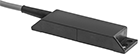
Tamper-Resistant Magnetically Actuated Switches
 |  | 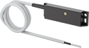 |
Style A with Wire Leads | Style B with Wire Leads | Style B with Wire Leads and LED Status Indicator |
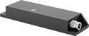 | 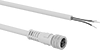 |  |
Style B with 4-Pole M8 Plug | Cords with Socket | Coded Magnet for Style A |
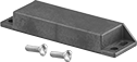 | ||
Coded Magnet for Style B |
Prevent unauthorized use—these switches require coded magnets (sold separately) to actuate, and cannot be bypassed using ordinary magnets. They actuate when a magnet comes within sensing distance, and reset when the magnet moves away. Mount the switch in a stationary position, such as a door frame, and mount the magnet to a movable object, such as the door. They’re often used to detect when a door or window opens, and can be used with movable machine guards. All are rated IP67 for protection from temporary submersion.
Safety relays are required in safety applications with switches that control two or three circuits.
LED Status Indicator—Switches with an LED status indicator light up when they’re actuated, so you can see if they’re wired correctly with a quick glance.
Switches | Cords with Socket | Coded Magnets | ||||||||||||||||||||
|---|---|---|---|---|---|---|---|---|---|---|---|---|---|---|---|---|---|---|---|---|---|---|
Style | No. of Circuits Controlled | Switch Starting Position | Switch Designation | Switching Current @ Voltage | Max. Voltage | Input Voltage | Max. Sensing Distance | Dia. | Lg. | Wd. | Ht. | Mounting Thread Size | Enclosure Rating | Each | Each | Mounting Hole Dia. | Each | |||||
Plastic Housing with Wire Leads | ||||||||||||||||||||||
| A | 1 | 1 On | SPST-NC | 6.3 amp @ 120V AC | 250V AC | 24V DC | 0.2" | 1.2" | 3.1" | — | — | M30 × 1.5 mm | IP67 | 7225K11 | 0000000 | ——— | 0 | 0.18" | 7225K12 | 000000 | ||
| A | 2 | 1 Off and 1 On | DPST-1NO/1NC | 0.28 amp @ 120V AC, 0.4 amp @ 170V DC | 120V AC 170V DC | 120V AC 170V DC | 0.2" | 1.2" | 1.3" | — | — | M30 × 1.5 mm | IP67 | 7225K21 | 00000 | ——— | 0 | 0.18" | 7225K22 | 00000 | ||
| B | 2 | 1 Off and 1 On | DPST-1NO/1NC | 0.5 amp @ 120V AC/120V DC | 120V AC 120V DC | 120V AC 120V DC | 0.2" | — | 3.5" | 1" | 0.5" | — | IP67 | 7202K12 | 000000 | ——— | 0 | 0.2" | 7202K21 | 00000 | ||
| B | 3 | 1 Off and 2 On | 3PST-1NO/2NC | 10 mA @ 24V DC | 24V DC | 24V DC | 0.2" | — | 3.5" | 1" | 0.5" | — | IP67 | 7202K11 | 000000 | ——— | 0 | 0.2" | 7202K21 | 00000 | ||
| B | 3 | 1 Off and 2 On | 3PST-1NO/2NC | 0.4 amp @ 100V AC/100V DC | 100V AC 100V DC | 100V AC 100V DC | 0.2" | — | 3.5" | 1" | 0.5" | — | IP67 | 7202K33 | 000000 | ——— | 0 | 0.2" | 7202K21 | 00000 | ||
Plastic Housing with Wire Leads and LED Status Indicator | ||||||||||||||||||||||
| B | 2 | 1 Off and 1 On | DPST-1NO/1NC | 10 mA @ 24V DC | 24V DC | 24V DC | 0.2" | — | 3.5" | 1" | 0.5" | — | IP67 | 7202K34 | 000000 | ——— | 0 | 0.2" | 7202K21 | 00000 | ||
Plastic Housing with 4-Pole M8 Plug and LED Status Indicator | ||||||||||||||||||||||
| B | 2 | 1 Off and 1 On | DPST-1NO/1NC | 10 mA @ 24V DC | 24V DC | 24V DC | 0.2" | — | 3.5" | 1" | 0.5" | — | IP67 | 7202K31 | 000000 | 7138K15 | 000000 | 0.2" | 7202K21 | 00000 | ||
| B | 3 | 1 Off and 2 On | 3PST-1NO/2NC | 10 mA @ 24V DC | 24V DC | 24V DC | 0.2" | — | 3.5" | 1" | 0.5" | — | IP67 | 7202K32 | 000000 | 7138K15 | 00000 | 0.2" | 7202K21 | 00000 | ||
Magnetic Contact Alarm Switches
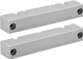 | 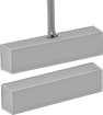 | 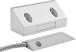 | 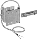 |
Style A with Screw Terminals | Style A with Wire Leads | Style B | Style D |
Style | No. of Circuits Controlled | Switch Starting Position | Switch Designation | Switching Current @ Voltage | Max. Sensing Distance | Wire Lead Lg., ft. | Lg. | Wd. | Ht. | Color | Environment | Enclosure Rating | Each | |||
|---|---|---|---|---|---|---|---|---|---|---|---|---|---|---|---|---|
Plastic Housing with Wire Leads | ||||||||||||||||
Adhesive Back with Sealed Housing | ||||||||||||||||
| A | 1 | 1 Off | SPST-NO | 0.5 amp @ 100V AC/100V DC | 0.62" | 1 | 1.5" | 0.25" | 0.37" | White | Corrosive, Dusty, Oily, Outdoor, Submersible, Washdown, Wet | NEMA 4X, NEMA 6, NEMA 12, IP67 | 8039A21 | 00000 | ||
Aluminum Housing with Wire Leads | ||||||||||||||||
Screw On with Flexible Stainless Steel Conduit and Sealed Housing | ||||||||||||||||
| A | 1 | 1 Off | SPST-NO | 0.5 amp @ 100V AC/100V DC | 3" | 3 | 3" | 0.5" | 1" | — | Corrosive, Dusty, Oily, Outdoor, Submersible, Washdown, Wet | NEMA 4X, NEMA 6, NEMA 12, IP67 | 8039A51 | 00000 | ||
| A | 1 | 1 Off or 1 On | SPDT | 0.25 amp @ 30V AC/30V DC | 3" | 3 | 3" | 0.5" | 1" | — | Corrosive, Dusty, Oily, Outdoor, Submersible, Washdown, Wet | NEMA 4X, NEMA 6, NEMA 12, IP67 | 8039A52 | 000000 | ||
| B | 1 | 1 Off | SPST-NO | 0.5 amp @ 100V AC/100V DC | 3" | 3 | 3.5" | 1.5" | 1.5" | — | Corrosive, Dusty, Oily, Outdoor, Submersible, Washdown, Wet | NEMA 4X, NEMA 6, NEMA 12, IP67 | 8135A11 | 00000 | ||
| B | 1 | 1 Off or 1 On | SPDT | 0.25 amp @ 30V AC/30V DC | 3" | 3 | 3.5" | 1.5" | 1.5" | — | Corrosive, Dusty, Oily, Outdoor, Submersible, Washdown, Wet | NEMA 4X, NEMA 6, NEMA 12, IP67 | 8135A32 | 00000 | ||
| D | 1 | 1 Off | SPST-NO | 0.5 amp @ 100V AC/100V DC | 3" | 2 | 3.62" | 0.68" | 3" | — | Corrosive, Dusty, Oily, Outdoor, Submersible, Washdown, Wet | NEMA 4X, NEMA 6, NEMA 12, IP67 | 80425A31 | 00000 | ||
DC Magnetic-Object Proximity Sensors
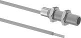 | 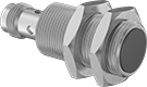 |
Flush with Wire Leads | Flush with Plug |
 |
3-Pole M8 Plug |
 |
4-Pole M12 Plug |
These sensors detect magnetic objects—or objects with a magnet attached—through non-magnetic walls. They’re often used to count magnetic items on a conveyor belt that are too far for other proximity sensors to detect and in food plants to track cleaners through stainless steel pipe. Producing a PNP signal output, these sensors are commonly used with programmable logic controllers (PLCs). Resistant to dust, heat, and vibration, sensors will stand up to harsh environments. Magnets are sold separately.
Maximum Sensing Distance—Maximum sensing distance in the table below represents sensors used with the magnet shown. Sensing distance will vary depending on the magnetic strength of the object your sensor is detecting.
Sensors | Magnets | Cables with Sockets | |||||||||||||||||||||
|---|---|---|---|---|---|---|---|---|---|---|---|---|---|---|---|---|---|---|---|---|---|---|---|
Switch Starting Position | Dia., mm | Max. Sensing Distance, mm | Magnetic Sensitivity, G | Output Digital Signal | Switching Freq. | Input Voltage | Current Output | Electrical Connection Type | No. of Wire Leads | Lg., mm | Circuit Protection | Cable Lead Lg., ft. | Cable OD | Temp. Range, ° F | Certification | Each | Each | Each | |||||
Nickel-Plated Brass Housing with Plastic Face (IP67) | |||||||||||||||||||||||
Flush with Wire Lead Connection | |||||||||||||||||||||||
| 1 Off | 8 | 55 | 10 | PNP | 1,000 Hz | 10V DC to 30V DC | 200 mA | Hardwire | 3 | 48 | Overload Reverse Polarity Short Circuit | 6 1/2 | 0.15" | -10 to 165 | CE Marked | 4684N16 | 0000000 | 4684N36 | 000000 | ——— | 0 | ||
| 1 Off | 12 | 81 | 6 | PNP | 1,000 Hz | 10V DC to 30V DC | 200 mA | Hardwire | 3 | 50 | Overload Reverse Polarity Short Circuit | 6 1/2 | 0.15" | -10 to 165 | CE Marked | 4684N13 | 000000 | 4684N36 | 00000 | ——— | 0 | ||
| 1 Off | 18 | 105 | 4 | PNP | 5 kHz | 10V DC to 30V DC | 200 mA | Hardwire | 3 | 58 | Overload Reverse Polarity Short Circuit | 6 1/2 | 0.15" | -10 to 165 | CE Marked | 4684N35 | 000000 | 4684N36 | 00000 | ——— | 0 | ||
| 1 On | 8 | 55 | 10 | PNP | 1,000 Hz | 10V DC to 30V DC | 200 mA | Hardwire | 3 | 48 | Overload Reverse Polarity Short Circuit | 10 | 0.15" | -10 to 165 | CE Marked | 4684N29 | 000000 | 4684N36 | 00000 | ——— | 0 | ||
| 1 On | 12 | 55 | 10 | PNP | 1,000 Hz | 10V DC to 30V DC | 200 mA | Hardwire | 3 | 48 | Overload Reverse Polarity Short Circuit | 6 1/2 | 0.15" | -10 to 165 | CE Marked | 4684N18 | 000000 | 4684N36 | 00000 | ——— | 0 | ||
Flush with 3-Pole M8 Plug Connection | |||||||||||||||||||||||
| 1 Off | 8 | 55 | 10 | PNP | 1,000 Hz | 10V DC to 30V DC | 200 mA | Plug In | — | 46 | Overload Reverse Polarity Short Circuit | — | — | -10 to 165 | CE Marked | 4684N21 | 000000 | 4684N36 | 00000 | 7138K14 | 000000 | ||
| 1 On | 8 | 55 | 10 | PNP | 1,000 Hz | 10V DC to 30V DC | 200 mA | Plug In | — | 46 | Overload Reverse Polarity Short Circuit | — | — | -10 to 165 | CE Marked | 4684N32 | 000000 | 4684N36 | 00000 | 7138K14 | 00000 | ||
Flush with 4-Pole M12 Plug Connection | |||||||||||||||||||||||
| 1 Off | 12 | 55 | 10 | PNP | 1,000 Hz | 10V DC to 30V DC | 200 mA | Plug In | — | 46 | Overload Reverse Polarity Short Circuit | — | — | -10 to 165 | CE Marked | 4684N24 | 000000 | 4684N36 | 00000 | 6897K36 | 00000 | ||
| 1 Off | 12 | 81 | 6 | PNP | 1,000 Hz | 10V DC to 30V DC | 200 mA | Plug In | — | 63 | Overload Reverse Polarity Short Circuit | — | — | -10 to 165 | CE Marked | 4684N12 | 000000 | 4684N36 | 00000 | 6897K36 | 00000 | ||
| 1 Off | 18 | 105 | 4 | PNP | 5 kHz | 10V DC to 30V DC | 200 mA | Plug In | — | 60 | Overload Reverse Polarity Short Circuit | — | — | -10 to 165 | CE Marked | 4684N34 | 000000 | 4684N36 | 00000 | 6897K36 | 00000 | ||
| 1 On | 18 | 69 | 7 | PNP | 5 kHz | 10V DC to 30V DC | 200 mA | Plug In | — | 50 | Overload Reverse Polarity Short Circuit | — | — | -10 to 165 | CE Marked | 4684N33 | 000000 | 4684N36 | 00000 | 6897K36 | 00000 | ||
RFID Safety Switches
 |
 |
 |
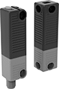
Replacement Actuator |
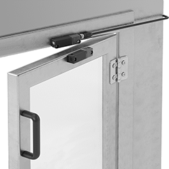
The convenient, modern alternative to mechanical safety switches. These RFID switches are easier to install, fit a wider range of access points, and can mount horizontally. Since they don't need a traditional key to actuate, they work even if the switch and actuator are slightly misaligned. Also known as interlock switches, they shut off power to equipment as soon as you open the barrier, which disconnects the RFID signal. These switches are often used with small machines. Find them anywhere from a CNC machine’s window to a packaging machine’s service panel. Mount the switch on the frame and the actuator on the barrier. Rated IP67 and IP69K, these switches are protected against temporary submersion and high-pressure, high-temperature washdowns.
For the Manufacturer User Manual, click on a part number and select Product Detail.
Magnetic Latch—Switches with a magnetic latch help prevent a barrier from opening by accident, such as from light bumps and low vibrations. The magnet keeps the actuator and switch from separating.
Number of Safety Outputs—The number of safety outputs, also known as output signal switching devices (OSSDs), tells you how many machines you can control. Each output has a pair of signals that shut down a single machine—if one signal fails, the other takes over as a failsafe.
Switches | Replacement Actuators | |||||||||||||||||||
|---|---|---|---|---|---|---|---|---|---|---|---|---|---|---|---|---|---|---|---|---|
Housing | Mounting | |||||||||||||||||||
No. of Safety Outputs | Holding Force, lbf | Max. Sensing Distance, mm | Input Voltage, V DC | Current Output, mA | Output Digital Signal | Ht. | Wd. | Dp. | Fasteners Included | No. of Slots | Slot Lg. | Slot Wd. | Features | Enclosure Rating | Each | Each | ||||
Plastic Housing | ||||||||||||||||||||
With 8-Pole M12 Plug | ||||||||||||||||||||
| 1 | 4 | 12 | 24 | 250 | PNP | 3.6" | 0.9" | 1" | No | 2 | 0.18" | 0.26" | Auxiliary PNP Output, Magnetic Latch | IP65, IP67, IP69K | 8049N102 | 0000000 | 8049N14 | 0000000 | ||
 |
Lg., ft. | Voltage | Current, amp | Cord OD | Enclosure Rating | Each | ||
|---|---|---|---|---|---|---|---|
| 3 | 30V AC/30V DC | 2 | 0.22" | IP66K, IP67 | 5059N39 | 000000 |
Tamper-Resistant Magnetic Contact Alarm Switches
 |  |  |
Flush Mount | Surface Mount | Surface Mount with Conduit Connection |
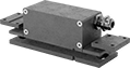
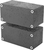
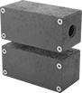
Prevent unauthorized use of doors or windows with a combination of coded magnets and contacts that wire to an alarm system. The coded magnets mean they can’t be bypassed with regular magnets. These switches actuate when the magnet comes within sensing distance of the switch and reset when the magnet moves away. Mount the magnet to your door or window and the switch to the frame. Connect the switch contacts to an alarm system, which will trigger when the magnet is pulled away as your door or window is opened.
Flush Mount—Flush-mount switches are designed to mount against the door jam. They have a cord grip to reduce strain on your cord.
Surface Mount—Surface-mount switches mount on the surface of your door.
Conduit Trade Size 1/2—Switches with a 1/2 conduit connection are ready to directly attach to your conduit.
No. of Circuits Controlled | Switch Starting Position | Switch Designation | Switching Current @ Voltage | Max. Sensing Distance | No. of Terminals | Conduit Trade Size | Lg. | Wd. | Ht. | Features | Enclosure Rating | Each | |||
|---|---|---|---|---|---|---|---|---|---|---|---|---|---|---|---|
Painted Zinc Housing with Screw Terminals | |||||||||||||||
Screw On—Flush Mount | |||||||||||||||
| 2 | 1 Off and 1 On | DPST-1NO/1NC | 0.2 amp @ 30V DC | 0.26" | 7 | — | 4.33" | 1.38" | 1.26" | Auxiliary NO (Normally Open) Alarm, Nickel-Plated Brass Cord Grip | IP67 | 7612N13 | 000000000 | ||
Screw On—Surface Mount | |||||||||||||||
| 2 | 1 Off and 1 On | DPST-1NO/1NC | 0.2 amp @ 30V DC | 0.26" | 7 | — | 2.96" | 1.38" | 1.34" | Auxiliary NO (Normally Open) Alarm | IP67 | 7612N12 | 00000000 | ||
| 2 | 1 Off and 1 On | DPST-1NO/1NC | 0.2 amp @ 30V DC | 0.26" | 7 | 1/2 | 2.96" | 1.38" | 1.34" | Auxiliary NO (Normally Open) Alarm | IP67 | 7612N11 | 00000000 | ||
Frame-Mounted RFID Safety Switches
 |  |
Switch Shown Installed with LED Status Indicator | Plastic Housing |
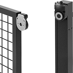
Prevent accidental bumps or vibration from triggering these safety switches unnecessarily—a strong magnet maintains the RFID signal between the actuator and switch until it's intentionally opened. Also known as interlock switches, they automatically cut power when you open an access door, interrupting the signal, then restore power when the door is closed, and the switch and actuator meet. They're designed to mount on a frame and a door, gate, or window. Use them in many ways—from turning off a machine-operated saw when you open the protective window to powering down robotic arms when someone enters the partitioned area. The LED indicator shows that your switch is on and whether it’s actuated.
For the Manufacturer User Manual, click on a part number and select Product Detail.
IP67 Enclosure Rating—IP67 rated switches protect against temporary submersion.
Number of Safety Outputs—The number of safety outputs, also known as output signal switching devices (OSSDs), tells you how many machines you can control. Each output has a pair of signals that shut down a single machine—if one signal fails, the other takes over as a failsafe.
Switches | Replacement Actuators | |||||||||||||||||
|---|---|---|---|---|---|---|---|---|---|---|---|---|---|---|---|---|---|---|
Housing | ||||||||||||||||||
No. of Safety Outputs | Holding Force, lbf | Max. Sensing Distance, mm | Input Voltage, V DC | Current Output, mA | Output Digital Signal | Cable Lead Lg. | Ht. | Wd. | Dp. | Mounting Fasteners Included | Features | Enclosure Rating | Each | Each | ||||
Plastic Housing | ||||||||||||||||||
With 8-Pole M12 Plug | ||||||||||||||||||
| 1 | 152 | 10 | 24 | 200 | PNP | 10" | 3.8" | 2.5" | 1.5" | Yes | Auxiliary PNP Output, LED Status Indicator, Magnetic Latch | IP67 | 8043N12 | 0000000 | 8043N13 | 0000000 | ||
 |
M12 cords connect switches to your system’s circuits.
Lg., ft. | Voltage | Current, amp | Cord OD | Housing Material | Enclosure Rating | Each | ||
|---|---|---|---|---|---|---|---|---|
| 10 | 30V AC/30V DC | 2 | 0.23" | Polyurethane Rubber | IP66K, IP67 | 4458N61 | 000000 |
Magnetic Position-Measuring Sensor Switch Transmitters
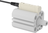 |  |
Shown With Air Cylinder |
 |
4-Pole M8 Plug |
 |
4-Pole M12 Plug |
Continuously monitor your air cylinder rod’s position and turn the cylinder on and off with a single component. These transmitters send positioning data to computers, programmable logic controllers (PLCs), and human-machine interfaces (HMIs). They're often integrated into automated systems for tasks such as timing when certain steps of your process should take place and verifying dimensions for quality control. Rated IP67, these transmitters withstand temporary submersion.
Press the buttons on the switch to toggle between voltage and current outputs. These transmitters have a plug that connects to cords with a socket (not included) so you can quickly connect and disconnect the switch.
Configurable Digital Output | Configurable Analog Output | ||||||||||||||||||
|---|---|---|---|---|---|---|---|---|---|---|---|---|---|---|---|---|---|---|---|
Sensing Distance, mm | Input Voltage, V DC | No. of | Control Communication Protocol | Digital Signal | No. of | Analog Signal | Sensing Distance Resolution, mm | Repeatability, mm | Lg. | Wd. | Ht. | Housing Material | Temp. Range, ° F | Certification | Color | Each | |||
4-Pole M8 Connection | |||||||||||||||||||
IP67 | |||||||||||||||||||
| 0 to 25 | 15 to 30 | 1 | IO-Link | PNP, NPN | 1 | 0V DC to 10V DC, 4 mA to 20 mA | 0.05 | -0.1 to 0.1 | 1 9/16" | 11/16" | 1/2" | Plastic | 15 to 140 | UL Listed, C-UL Listed, CE Marked | White | 6516N11 | 0000000 | ||
| 0 to 50 | 15 to 30 | 1 | IO-Link | PNP, NPN | 1 | 0V DC to 10V DC, 4 mA to 20 mA | 0.05 | -0.1 to 0.1 | 2 9/16" | 11/16" | 1/2" | Plastic | 15 to 140 | UL Listed, C-UL Listed, CE Marked | White | 6516N13 | 000000 | ||
| 0 to 100 | 15 to 30 | 1 | IO-Link | PNP, NPN | 1 | 0V DC to 10V DC, 4 mA to 20 mA | 0.05 | -0.1 to 0.1 | 4 1/2" | 11/16" | 1/2" | Plastic | 15 to 140 | UL Listed, C-UL Listed, CE Marked | White | 6516N15 | 000000 | ||
| 0 to 200 | 15 to 30 | 1 | IO-Link | PNP, NPN | 1 | 0V DC to 10V DC, 4 mA to 20 mA | 0.05 | -0.1 to 0.1 | 8 7/16" | 11/16" | 1/2" | Plastic | 15 to 140 | UL Listed, C-UL Listed, CE Marked | White | 6516N17 | 000000 | ||
4-Pole M12 Connection | |||||||||||||||||||
IP67 | |||||||||||||||||||
| 0 to 25 | 15 to 30 | 1 | IO-Link | PNP, NPN | 1 | 0V DC to 10V DC, 4 mA to 20 mA | 0.05 | -0.1 to 0.1 | 1 9/16" | 11/16" | 1/2" | Plastic | 15 to 140 | UL Listed, C-UL Listed, CE Marked | White | 6516N12 | 000000 | ||
| 0 to 50 | 15 to 30 | 1 | IO-Link | PNP, NPN | 1 | 0V DC to 10V DC, 4 mA to 20 mA | 0.05 | -0.1 to 0.1 | 2 9/16" | 11/16" | 1/2" | Plastic | 15 to 140 | UL Listed, C-UL Listed, CE Marked | White | 6516N14 | 000000 | ||
| 0 to 100 | 15 to 30 | 1 | IO-Link | PNP, NPN | 1 | 0V DC to 10V DC, 4 mA to 20 mA | 0.05 | -0.1 to 0.1 | 4 1/2" | 11/16" | 1/2" | Plastic | 15 to 140 | UL Listed, C-UL Listed, CE Marked | White | 6516N16 | 000000 | ||
| 0 to 200 | 15 to 30 | 1 | IO-Link | PNP, NPN | 1 | 0V DC to 10V DC, 4 mA to 20 mA | 0.05 | -0.1 to 0.1 | 8 7/16" | 11/16" | 1/2" | Plastic | 15 to 140 | UL Listed, C-UL Listed, CE Marked | White | 6516N18 | 000000 | ||
Tamper-Resistant RFID Safety Switches
 |
 |
Replacement Actuator |
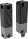 |
Block access to machinery while it's running. These safety switches cut power when their signal disconnects, shutting off equipment as you open machine guards. They link to a single actuator, so no other RFID tag or card can interfere. The unique RFID code means that once the power is cut, no one can bypass the switch and restart equipment while the guard is open.
These switches are often used with small machines where there’s no risk of the barrier closing on its own. Find them anywhere from a CNC machine’s window to a machine-operated saw’s service panel. Mount the switch on the frame and the actuator on the barrier. They're also known as interlock switches. Rated IP67 and IP69K, these switches are protected against temporary submersion and high-pressure, high-temperature washdowns.
For the Manufacturer User Manual, click on a part number and select Product Detail.
Magnetic Latch—Switches with a magnetic latch prevent guards from opening by accident, such as from light bumps and low vibrations.
Number of Safety Outputs—The number of safety outputs, also known as output signal switching devices (OSSDs), tells you how many machines you can control. Each output has a pair of signals that shut down a single machine—if one signal fails, the other takes over as a failsafe.
Switches | Replacement Actuators | |||||||||||||||||||
|---|---|---|---|---|---|---|---|---|---|---|---|---|---|---|---|---|---|---|---|---|
Housing | Mounting | |||||||||||||||||||
No. of Safety Outputs | Holding Force, lbf | Max. Sensing Distance, mm | Input Voltage, V DC | Current Output, mA | Output Digital Signal | Ht. | Wd. | Dp. | Fasteners Included | No. of Slots | Slot Lg. | Slot Wd. | Features | Enclosure Rating | Each | Each | ||||
Plastic Housing | ||||||||||||||||||||
With 8-Pole M12 Plug | ||||||||||||||||||||
| 1 | 4 | 12 | 24 | 250 | PNP | 3.6" | 0.9" | 1" | No | 2 | 0.18" | 0.26" | Auxiliary PNP Output, Magnetic Latch, Unique RFID Code | IP65, IP67, IP69K | 7681N112 | 0000000 | 7681N12 | 0000000 | ||
|
Lg., ft. | Voltage | Current, amp | Cord OD | Enclosure Rating | Each | ||
|---|---|---|---|---|---|---|---|
| 3 | 30V AC/30V DC | 2 | 0.22" | IP66K, IP67 | 5059N39 | 000000 |
