Filter by
System of Measurement
For Use With
Fitting Connection

Manifold Flow Pattern

Maximum Pressure @ Temperature
Number of Inlets
Oil Outlet Connection
Outlet Spacing
Outlet Location
Export Control Classification Number (ECCN)
Minimum Temperature
Maximum Temperature
DFARS Specialty Metals
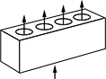
Straight-Flow Rectangular Manifolds
Anodized Aluminum—UNF Inlets × UNF Outlets
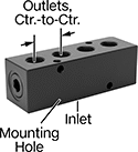 |  |
Anodized aluminum manifolds are the industry standard for the most common types of applications. They are lighter in weight than other metal manifolds and have good corrosion resistance. These manifolds are anodized for a black finish.
Inlet | Outlet | |||||||||||||||
|---|---|---|---|---|---|---|---|---|---|---|---|---|---|---|---|---|
No. of Outlets | Thread Size | Dash Size | Thread Size | Dash Size | Lg. | Wd. | Ht. | Outlet Ctr.-to-Ctr. | Color | Temp. Range, ° F | Max. Pressure | Manifold Flow Pattern | Each | |||
Standard Outlet Spacing | ||||||||||||||||
| 2 | 9/16"-18 | 06 | 7/16"-20 | 04 | 2 1/8" | 1 1/4" | 1 1/4" | 7/8" | Black | -10 to 200 | Air: 1,000 psi @ 72° F Water: 1,000 psi @ 72° F Hydraulic Fluid: 3,000 psi @ 72° F | Straight | 1023N355 | 000000 | ||
| 2 | 1 1/16"-12 | 12 | 3/4"-16 | 08 | 4" | 2" | 2" | 1 1/2" | Black | -10 to 200 | Air: 1,000 psi @ 72° F Water: 1,000 psi @ 72° F Hydraulic Fluid: 3,000 psi @ 72° F | Straight | 1023N357 | 00000 | ||
| 3 | 1 1/16"-12 | 12 | 3/4"-16 | 08 | 5 1/2" | 2" | 2" | 1 1/2" | Black | -10 to 200 | Air: 1,000 psi @ 72° F Water: 1,000 psi @ 72° F Hydraulic Fluid: 3,000 psi @ 72° F | Straight | 1023N363 | 00000 | ||
| 3 | 1 5/16"-12 | 16 | 1 1/16"-12 | 12 | 7" | 2 1/2" | 2 1/2" | 2" | Black | -10 to 200 | Air: 1,000 psi @ 72° F Water: 1,000 psi @ 72° F Hydraulic Fluid: 3,000 psi @ 72° F | Straight | 1023N364 | 000000 | ||
| 4 | 9/16"-18 | 06 | 7/16"-20 | 04 | 3 7/8" | 1 1/4" | 1 1/4" | 7/8" | Black | -10 to 200 | Air: 1,000 psi @ 72° F Water: 1,000 psi @ 72° F Hydraulic Fluid: 3,000 psi @ 72° F | Straight | 1023N367 | 00000 | ||
| 4 | 3/4"-16 | 08 | 9/16"-18 | 06 | 4 3/4" | 1 1/2" | 1 1/2" | 1" | Black | -10 to 200 | Air: 1,000 psi @ 72° F Water: 1,000 psi @ 72° F Hydraulic Fluid: 3,000 psi @ 72° F | Straight | 1023N368 | 00000 | ||
| 4 | 1 1/16"-12 | 12 | 3/4"-16 | 08 | 7" | 2" | 2" | 1 1/2" | Black | -10 to 200 | Air: 1,000 psi @ 72° F Water: 1,000 psi @ 72° F Hydraulic Fluid: 3,000 psi @ 72° F | Straight | 1023N369 | 00000 | ||
| 6 | 9/16"-18 | 06 | 7/16"-20 | 04 | 5 5/8" | 1 1/4" | 1 1/4" | 7/8" | Black | -10 to 200 | Air: 1,000 psi @ 72° F Water: 1,000 psi @ 72° F Hydraulic Fluid: 3,000 psi @ 72° F | Straight | 1023N373 | 00000 | ||
| 6 | 1 5/16"-12 | 16 | 1 1/16"-12 | 12 | 13" | 2 1/2" | 2 1/2" | 2" | Black | -10 to 200 | Air: 1,000 psi @ 72° F Water: 1,000 psi @ 72° F Hydraulic Fluid: 3,000 psi @ 72° F | Straight | 1023N376 | 000000 | ||
| 8 | 7/16"-20 | 04 | 5/16"-24 | 02 | 6 1/4" | 1" | 1" | 3/4" | Black | -10 to 200 | Air: 1,000 psi @ 72° F Water: 1,000 psi @ 72° F Hydraulic Fluid: 3,000 psi @ 72° F | Straight | 1023N378 | 00000 | ||
| 8 | 9/16"-18 | 06 | 7/16"-20 | 04 | 7 3/8" | 1 1/4" | 1 1/4" | 7/8" | Black | -10 to 200 | Air: 1,000 psi @ 72° F Water: 1,000 psi @ 72° F Hydraulic Fluid: 3,000 psi @ 72° F | Straight | 1023N379 | 00000 | ||
Flow-Adjustment Valve Manifolds for Sealed Systems
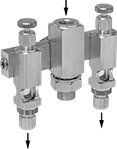 |  |  |
2 Oil Outlets | 3 Oil Outlets | 4 Oil Outlets |
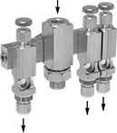
A sealed design prevents contamination in dirty and dusty environments. Use these manifolds to serve multiple lubrication points from a single location. Adjust the flow to individual lubrication points by turning the dial on the corresponding valve. Each valve can be removed for cleaning without disturbing the rest of the system. They can be used with any oil grade. Flow rate depends on temperature. They have NPTF (Dryseal) threads, which are compatible with NPT threads.
Oil Outlet | Oil Inlet | Overall | |||||||||||||||||
|---|---|---|---|---|---|---|---|---|---|---|---|---|---|---|---|---|---|---|---|
No. of | For Tube OD | Gender | Location | Thread Type | Pipe Size | Gender | Ht. | Wd. | Dp. | Max. Oil Outlet Pressure, psi | Material | Temp. Range, ° F | Mounting Thread Size | Features | For Use With | Each | |||
| 2 | 1/4" | Female | Top | NPTF | 1/4 | Female | 3 13/16" | 4 3/16" | 1 11/16" | 125 | Aluminum | -30 to 250 | 5/8"-18 | Glass Flow Sight | Oil | 1069K11 | 0000000 | ||
| 3 | 1/4" | Female | Top | NPTF | 1/4 | Female | 3 13/16" | 4 15/16" | 1 11/16" | 125 | Aluminum | -30 to 250 | 5/8"-18 | Glass Flow Sight | Oil | 1069K12 | 000000 | ||
| 4 | 1/4" | Female | Top | NPTF | 1/4 | Female | 3 13/16" | 5 11/16" | 1 11/16" | 125 | Aluminum | -30 to 250 | 5/8"-18 | Glass Flow Sight | Oil | 1069K13 | 000000 | ||
Flow-Adjustment Valve Manifolds for Vented Systems
| | |
2 Oil Outlets | 3 Oil Outlets | 4 Oil Outlets |
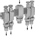
For use in clean environments, these manifolds have multiple air vents that keep pressure balanced. Use them to serve multiple lubrication points from a single location. Adjust the flow to individual lubrication points by turning the dial on the corresponding valve. Each valve can be removed for cleaning without disturbing the rest of the system. They can be used with any oil grade. Flow rate depends on temperature. They have NPTF (Dryseal) threads, which are compatible with NPT threads.
Oil Outlet | Oil Inlet | Overall | |||||||||||||||||
|---|---|---|---|---|---|---|---|---|---|---|---|---|---|---|---|---|---|---|---|
No. of | For Tube OD | Gender | Location | Thread Type | Pipe Size | Gender | Ht. | Wd. | Dp. | Max. Oil Outlet Pressure | Material | Temp. Range, ° F | Mounting Thread Size | Features | For Use With | Each | |||
| 2 | 1/4" | Female | Top | NPTF | 1/4 | Female | 3 13/16" | 4 3/16" | 1 11/16" | Not Rated | Aluminum | -30 to 250 | 5/8"-18 | Glass Flow Sight | Oil | 1069K21 | 0000000 | ||
| 3 | 1/4" | Female | Top | NPTF | 1/4 | Female | 3 13/16" | 4 15/16" | 1 11/16" | Not Rated | Aluminum | -30 to 250 | 5/8"-18 | Glass Flow Sight | Oil | 1069K22 | 000000 | ||
| 4 | 1/4" | Female | Top | NPTF | 1/4 | Female | 3 13/16" | 5 11/16" | 1 11/16" | Not Rated | Aluminum | -30 to 250 | 5/8"-18 | Glass Flow Sight | Oil | 1069K23 | 000000 | ||
Oil-Dispensing Pump Metering Valves
Oil Outlet | Oil Inlet | ||||||||||||||
|---|---|---|---|---|---|---|---|---|---|---|---|---|---|---|---|
Thread Type | Pipe Size | Thread Size | Gender | Thread Type | Thread Size | Gender | Max. Oil Outlet Pressure, psi | Lg. | Hex Wd., mm | Material | Temp. Range, ° F | Choose a Flow Rate Trade Number | Each | ||
| NPT | 1/8 | — | Male | UNF | 5/16"-24 | Male | 200 | 1" | 10 | Brass | 32 to 120 | 00, 0, 1, 2, 3, 4, 5 | 2293K12 | 000000 | |
| UNF | — | 5/16"-24 | Male | UNF | 5/16"-24 | Male | 200 | 1" | 10 | Brass | 32 to 120 | 00, 0, 1, 2, 3, 4, 5 | 2293K11 | 00000 | |
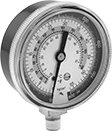
Refrigerant Pressure Testing and Charging Manifolds
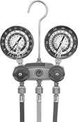 |
Two Valve |
Monitor refrigerant pressure with analog gauges when servicing air conditioning systems. All manifolds have double O-ring piston valves.