


Filter by
Push-Button Style

Illumination
System of Measurement
Push-Button Shape

Switch Action
Actuator Base Material
Actuator Style

Number of Terminals
Bulb Type
Hazardous Location Rating
UL File Number
U.S.–Mexico–Canada Agreement (USMCA) Qualifying
DFARS Specialty Metals
Export Control Classification Number (ECCN)
REACH
RoHS

About Electrical Switches
Choose a switch with the right trigger type, number of inputs, and control functions to power your equipment.
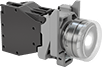
Hazardous Location 22 mm Panel-Mount Push-Button Switches
 |  |  |  |
Black Switch | Green Switch | White Switch | Red Switch |
 |  | 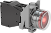 | |
Illuminated Green Switch | Illuminated White Switch | Illuminated Red Switch |
No. of Circuits Controlled | Switch Starting Position | Switch Action | No. of Terminals | Switch Designation | Switching Current @ Voltage | Dia. | For Max. Panel Thk. | Dp. Behind Panel | For Max. No. of Contact Blocks | Bulb Voltage | Actuator Color | Enclosure Rating | Each | |||
|---|---|---|---|---|---|---|---|---|---|---|---|---|---|---|---|---|
Metal Actuator Base with Screw-Terminal Wire Connection—Not Illuminated (600V AC/300V DC Maximum Voltage) | ||||||||||||||||
Flush | ||||||||||||||||
| 1 | 1 Off | Momentary | 3 | SPST-NO | 6 amp @ 120V AC, 2.8 amp @ 24V DC | 1 3/16" | 0.24" | 2 1/4" | 6 | — | Black | IP66, NEMA 4X, NEMA 13 | 8022N11 | 000000 | ||
| 1 | 1 Off | Momentary | 3 | SPST-NO | 6 amp @ 120V AC, 2.8 amp @ 24V DC | 1 3/16" | 0.24" | 2 1/4" | 6 | — | Green | IP66, NEMA 4X, NEMA 13 | 8022N12 | 00000 | ||
| 1 | 1 Off | Momentary | 3 | SPST-NO | 6 amp @ 120V AC, 2.8 amp @ 24V DC | 1 3/16" | 0.24" | 2 1/4" | 6 | — | White | IP66, NEMA 4X, NEMA 13 | 8022N14 | 000000 | ||
| 1 | 1 On | Momentary | 3 | SPST-NC | 6 amp @ 120V AC, 2.8 amp @ 24V DC | 1 3/16" | 0.24" | 2 1/4" | 6 | — | Red | IP66, NEMA 4X, NEMA 13 | 8022N13 | 000000 | ||
Metal Actuator Base with Screw-Terminal Wire Connection—Illuminated (600V AC/300V DC Maximum Voltage) | ||||||||||||||||
Flush | ||||||||||||||||
| 1 | 1 Off | Momentary | 3 | SPST-NO | 6 amp @ 120V AC, 2.8 amp @ 24V DC | 1 1/8" | 0.24" | 2 1/4" | 6 | 24V AC/24V DC | Green | IP66, NEMA 4X, NEMA 13 | 8022N15 | 000000 | ||
| 1 | 1 Off | Momentary | 3 | SPST-NO | 6 amp @ 120V AC, 2.8 amp @ 24V DC | 1 1/8" | 0.24" | 2 1/4" | 6 | 24V AC/24V DC | White | IP66, NEMA 4X, NEMA 13 | 8022N17 | 000000 | ||
| 1 | 1 On | Momentary | 3 | SPST-NC | 6 amp @ 120V AC, 2.8 amp @ 24V DC | 1 1/8" | 0.24" | 2 1/4" | 6 | 24V AC/24V DC | Red | IP66, NEMA 4X, NEMA 13 | 8022N16 | 000000 | ||
 |
Additional contact blocks can be added to control more circuits, or replace the included contact block.
No. of Circuits Controlled | Switch Starting Position | No. of Terminals | Switch Designation | Switching Current @ Voltage | Max. Voltage | Wire Connection | Each | ||
|---|---|---|---|---|---|---|---|---|---|
| 1 | 1 Off | 3 | SPST-NO | 6 amp @ 120V AC, 2.8 amp @ 24V DC | 600V AC/300V DC | Screw Terminal | 8022N18 | 000000 | |
| 1 | 1 On | 3 | SPST-NC | 6 amp @ 120V AC, 2.8 amp @ 24V DC | 600V AC/300V DC | Screw Terminal | 8022N19 | 00000 |
