


Filter by
Electrical Connection


Electrical Connector Component

Voltage
Mounting Location
Maximum Temperature
Control Communication Protocol
DFARS Specialty Metals
Export Control Classification Number (ECCN)
Automatic Robot Tool Changers
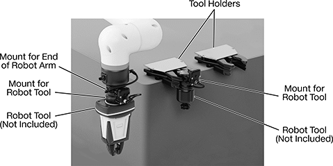 |
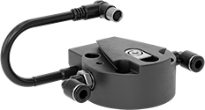
End-of-Robot-Arm Mounts
 |  |
With Air and Electric Pass-Through |
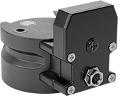
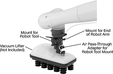
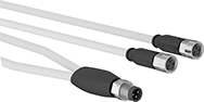
All mounts have air connections that let compressed air or vacuum pass through the mount, so you don’t have to run external lines that would get in the way of tool changes. They include two push-to-connect fittings to easily connect tubing. If air power is not needed, or if you prefer to use your own fittings, remove the included fittings.
With Air and Electric Pass-Through—Mounts with air and electric pass-throughs also route power, so you can switch between air-powered and electric tools in the same cycle. For example, you can use them with an electric vacuum lifter, then swap to air-powered grippers. They have a built-in 8-pole Nano M8 socket that connects directly to your robot arm.
Electrical Connection | Female Air Inlets | ||||||||||||
|---|---|---|---|---|---|---|---|---|---|---|---|---|---|
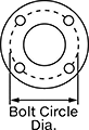
Bolt Circle Dia. (Mounting Pattern Compatibility) | Bolt Hole Thread Size (No. of) | Type | No. of Poles | Coding | No. of | Connection | Connection Port | For Tube OD, mm | Mounting Fasteners Included | Each | |||
With Air and Electric Pass-Through | |||||||||||||
| 50 mm (ISO 50) | M6 × 1 mm (4) | M8 Socket | 8 | A | 2 | Push to Connect | Tube | 6 | No | 3685N102 | 0000000 | ||
Robot-Tool Mounts
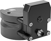 |  | |
With Air and Electric Pass-Through (Plug) | With Air and Electric Pass-Through (Socket) |
Electrical Connection | Female Air Outlets | |||||||||||
|---|---|---|---|---|---|---|---|---|---|---|---|---|
Bolt Circle Dia. (Mounting Pattern Compatibility) | Bolt Hole Thread Size (No. of) | Type | No. of Poles | Coding | No. of | Thread Type | Pipe Size | Mounting Fasteners Included | Each | |||
With Air and Electric Pass-Through | ||||||||||||
| 50 mm (ISO 50) | M6 × 1 mm (4) | M8 Plug | 8 | A | 2 | BSPP | 1/8 | No | 3685N104 | 0000000 | ||
| 50 mm (ISO 50) | M6 × 1 mm (4) | M8 Socket | 8 | A | 2 | BSPP | 1/8 | No | 3685N105 | 000000 | ||


IO-Link I/O Modules
 |
Components Sold Separately |
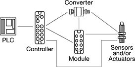
Create a system of sensors and actuators that you can remotely update, view measurements from, and receive error messages in real time. IO-Link systems minimize downtime by locating issues such as cut cables or dirty sensors quickly. They send only digital signals to your PLC, regardless of whether your sensors and actuators send digital or analog signals. Because these systems send digital signals, they’re more reliable and less prone to data error and signal loss than analog signals. It also means you don't have to use expensive shielded cables since they resist EMI.
When retrofitting an existing system, you'll need to make sure your PLC can incorporate IO-Link. Check with your PLC manufacturer—most have hardware that allows you to upgrade your PLC to run IO-Link.
Note: Sockets may have extra holes on their face that are not used.
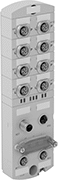
Modules
Surface Mount |
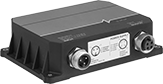
Modules communicate between your sensors and actuators and your PLC. They are required. Setting memory automatically stores your settings and restores them once your device is back online. This eliminates needing to program a device again when you replace or fix it.
Surface Mount—Surface mount modules let you mount modules on equipment such as tanks and conveyors. By mounting them on your equipment, you save space in your control cabinet. They use M12 connectors.
IP66 Enclosure Rating—IP66 rated components withstand washdowns.
IP67 Enclosure Rating—IP67 rated components can be temporarily submerged in water.
IP69K Enclosure Rating—IP69K rated components hold up to high-pressure and high-temperature washdowns.
Enclosure Rating—IP rated components block out dust and withstand some water, so they do not require an enclosure. Ports that are unused must be capped to maintain their rating.
Input | Output | ||||||||||||||||
|---|---|---|---|---|---|---|---|---|---|---|---|---|---|---|---|---|---|
Communication Protocol | No. of Device Ports | Total No. of M12 Connections | Type | Digital Signal | Voltage, V DC | No. of | Type | Digital Signal | Voltage, V DC | Current, amp | No. of | Operating Voltage, V DC | Certification | Each | |||
Surface Mount | |||||||||||||||||
IP66, IP67 | |||||||||||||||||
| IO-Link, EtherNet/IP | 4 | 7 | Digital | PNP | 0 to 30 | 8 | Digital | PNP | 30 | 0.3 | 4 | 20 to 30 | UL Listed, C-UL Listed, CE Marked | 7585N13 | 0000000 | ||
| IO-Link, EtherNet/IP | 8 | 11 | Digital | PNP | 0 to 30 | 16 | Digital | PNP | 30 | 0.3 | 8 | 20 to 30 | UL Listed, C-UL Listed, CE Marked | 7585N14 | 000000 | ||
| IO-Link, PROFINET | 4 | 7 | Digital | PNP | 0 to 30 | 8 | Digital | PNP | 30 | 0.3 | 4 | 20 to 30 | UL Listed, C-UL Listed, CE Marked | 7585N11 | 000000 | ||
| IO-Link, PROFINET | 8 | 11 | Digital | PNP | 0 to 30 | 16 | Digital | PNP | 30 | 0.3 | 8 | 20 to 30 | UL Listed, C-UL Listed, CE Marked | 7585N12 | 000000 | ||
IP66, IP67, IP69K | |||||||||||||||||
| IO-Link, EtherNet/IP | 4 | 7 | Digital | PNP | 0 to 30 | 8 | Digital | PNP | 30 | 0.3 | 4 | 20 to 30 | UL Listed, C-UL Listed, CE Marked | 7585N19 | 000000 | ||
| IO-Link, EtherNet/IP | 8 | 11 | Digital | PNP | 0 to 30 | 16 | Digital | PNP | 30 | 0.3 | 8 | 20 to 30 | UL Listed, C-UL Listed, CE Marked | 7585N21 | 000000 | ||
| IO-Link, PROFINET | 4 | 7 | Digital | PNP | 0 to 30 | 8 | Digital | PNP | 30 | 0.3 | 4 | 20 to 30 | UL Listed, C-UL Listed, CE Marked | 7585N17 | 000000 | ||
| IO-Link, PROFINET | 8 | 11 | Digital | PNP | 0 to 30 | 16 | Digital | PNP | 30 | 0.3 | 8 | 20 to 30 | UL Listed, C-UL Listed, CE Marked | 7585N18 | 000000 | ||
Expansion Modules
 |
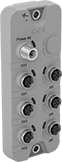
Expansion modules increase the number of inputs and outputs in your IO-Link system, so you can add more sensors and actuators to your network. Connect multiple devices to each expansion module using M12 connectors, without needing to wire your devices inside a control cabinet. They transmit signals from multiple devices with a single cord. Expansion modules are optional, but when used, they must connect to a controller. Mount them on your equipment to save space in your control cabinet.
IP65 Enclosure Rating—IP65 rated components can be rinsed.
IP67 Enclosure Rating—IP67 rated components can be temporarily submerged in water.
IP69K Enclosure Rating—IP69K rated components hold up to high-pressure and high-temperature washdowns.
Enclosure Rating—IP rated components block out dust and withstand some water, so they do not require an enclosure. Ports that are unused must be capped to maintain their rating.
Input | Output | ||||||||||||||||
|---|---|---|---|---|---|---|---|---|---|---|---|---|---|---|---|---|---|
Expansion Module Type | Communication Protocol | No. of Device Ports | Total No. of M12 Connections | Type | Digital Signal | Voltage, V DC | No. of | Type | Digital Signal | Current, amp | No. of | Operating Voltage, V DC | Certification | Each | |||
Surface Mount | |||||||||||||||||
IP65, IP67 | |||||||||||||||||
| Input | IO-Link | 6 | 7 | Digital | PNP | 16 to 30 | 12 | — | — | — | — | 18 to 30 | UL Listed, C-UL Listed, CE Marked | 7603N11 | 0000000 | ||
| Input | IO-Link | 10 | 11 | Digital | PNP | 16 to 30 | 20 | — | — | — | — | 18 to 30 | UL Listed, C-UL Listed, CE Marked | 7603N12 | 000000 | ||
| Input, Output | IO-Link | 8 | 10 | Digital | PNP | 18 to 30 | 16 | Digital | PNP | 3.6 | 16 | 18 to 30 | CE Marked | 7603N15 | 000000 | ||
| Output | IO-Link | 6 | 8 | — | — | — | — | Digital | PNP | 3.6 | 12 | 18 to 30 | UL Listed, C-UL Listed, CE Marked | 7603N13 | 000000 | ||
| Output | IO-Link | 10 | 12 | — | — | — | — | Digital | PNP | 3.6 | 20 | 18 to 30 | UL Listed, C-UL Listed, CE Marked | 7603N14 | 000000 | ||
IP65, IP67, IP69K | |||||||||||||||||
| Input | IO-Link | 6 | 7 | Digital | PNP | 16 to 30 | 12 | — | — | — | — | 18 to 30 | UL Listed, C-UL Listed, CE Marked | 7603N16 | 000000 | ||
| Input | IO-Link | 10 | 11 | Digital | PNP | 16 to 30 | 20 | — | — | — | — | 18 to 30 | UL Listed, C-UL Listed, CE Marked | 7603N17 | 000000 | ||
| Input, Output | IO-Link | 8 | 10 | Digital | PNP | 18 to 30 | 16 | Digital | PNP | 3.6 | 16 | 18 to 30 | CE Marked | 7603N21 | 000000 | ||
| Output | IO-Link | 6 | 8 | — | — | — | — | Digital | PNP | 3.6 | 12 | 18 to 30 | UL Listed, C-UL Listed, CE Marked | 7603N18 | 000000 | ||
| Output | IO-Link | 10 | 12 | — | — | — | — | Digital | PNP | 3.6 | 20 | 18 to 30 | UL Listed, C-UL Listed, CE Marked | 7603N19 | 000000 | ||
Converters
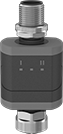 |
Converters translate analog signals to digital signals, making sensors and actuators IO-Link compatible. They are required to connect analog components to controllers and modules.
IP67 Enclosure Rating—IP67 rated components can be temporarily submerged in water.
Input | Output | |||||||||||||
|---|---|---|---|---|---|---|---|---|---|---|---|---|---|---|
Signal Converter Type | Total No. of M12 Connections | Signal Type | Digital Signal | Analog Signal | No. of | Signal Type | Digital Signal | Analog Signal | No. of | Certification | Each | |||
M12 Plug In | ||||||||||||||
Washdown (IP67) | ||||||||||||||
| Analog to Digital | 2 | Analog | — | 0V DC to 10V DC | 2 | Digital | PNP | — | 1 | UL Listed, C-UL Listed, CE Marked | 7603N52 | 0000000 | ||
| Analog to Digital to Analog | 2 | Analog | — | 4 mA to 20 mA | 1 | Digital, Analog | PNP | 4 mA to 20 mA | 2 | UL Listed, C-UL Listed, CE Marked | 7603N51 | 000000 | ||
| Digital to Analog | 2 | Digital | PNP | — | 1 | Analog | — | 0V DC to 10V DC | 2 | UL Listed, C-UL Listed, CE Marked | 7603N53 | 000000 | ||
| Digital to Analog | 2 | Digital | PNP | — | 1 | Analog | — | 4 mA to 20 mA | 2 | UL Listed, C-UL Listed, CE Marked | 7603N54 | 000000 | ||
Caps
 |
For Plugs |
 |
For Sockets |
For Thread | ||||||||
|---|---|---|---|---|---|---|---|---|
Size | Location | Material | Temp. Range, ° F | Includes | Each | |||
For Plugs, For Receptacles | ||||||||
| M12 | External | Anodized Aluminum | 0 to 220 | Lanyard | 6897K73 | 000000 | ||
| M12 | External | Stainless Steel | 0 to 220 | Lanyard | 6897K75 | 00000 | ||
For Receptacles, For Sockets | ||||||||
| M12 | Internal | Anodized Aluminum | 0 to 220 | — | 6897K74 | 00000 | ||
| M12 | Internal | Stainless Steel | 0 to 220 | Lanyard | 6897K59 | 00000 | ||
M12 Connectors
Plugs
 |
Shielded |
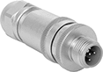
Shielded—Shielding blocks electrical noise from motors, drives, and other equipment, preventing erratic readings, false triggers, and data errors that cause downtime. Use these connectors near high-interference sources or anywhere with shielded cable, such as fieldbus networks, sensors, and encoders.
Adapters
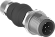 |
Adapter |
Plug | Socket | |||||||||
|---|---|---|---|---|---|---|---|---|---|---|
Coding | No. of Poles | Coding | No. of Poles | Voltage | Current, amp | Enclosure Rating | Each | |||
M12 Plug × M8 Socket | ||||||||||
| A | 3 | A | 3 | 50V AC/60V DC | 4 | IP67 | 5490N111 | 000000 | ||
| A | 4 | A | 4 | 50V AC/60V DC | 4 | IP67 | 5490N112 | 00000 | ||
M12 Plug × M22 Socket | ||||||||||
| A | 3 | — | 3 | 300V AC/300V DC | 4 | IP67 | 4362N11 | 00000 | ||
| A | 4 | — | 4 | 300V AC/300V DC | 4 | IP67 | 4362N12 | 00000 | ||
| A | 5 | — | 5 | 300V AC/300V DC | 4 | IP67 | 4362N13 | 00000 | ||
M22 Plug × M12 Socket | ||||||||||
| — | 3 | A | 3 | 300V AC/300V DC | 4 | IP67 | 4362N14 | 00000 | ||
| — | 4 | A | 4 | 300V AC/300V DC | 4 | IP67 | 4362N15 | 00000 | ||
| — | 5 | A | 5 | 300V AC/300V DC | 4 | IP67 | 4362N16 | 00000 | ||
M12 Socket × RJ45 Socket | ||||||||||
| — | — | A | 8 | 42V DC | 1.5 | IP67 | 8256T59 | 00000 | ||
| — | — | D | 4 | 48V AC/60V DC | 4 | IP65, IP67 | 8256T3 | 00000 | ||
| — | — | X | 8 | 50V AC/60V DC | 0.5 | IP67 | 8256T42 | 00000 | ||

M35 Connectors
M8 Connectors
Mini Splitters
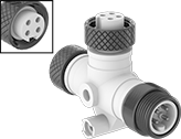 |
Plug × Socket × Socket |
2 Poles | 3 Poles |
4 Poles | 5 Poles |
6 Poles |
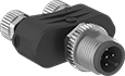
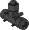
Simplify wiring and reduce the number of cords in your automation setup. These splitters create a branch off a main cord or connect multiple devices with a mini connection to a single port in a junction box or I/O module. A threaded housing securely mates with other mini connectors to keep out contaminants and won’t come loose from shaking or vibration. They have a standard pole layout and housing thread size to reduce the chance you’ll mis-mate connectors.
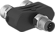
Tee Splitters
Plug | Sockets | ||||||||||||||
|---|---|---|---|---|---|---|---|---|---|---|---|---|---|---|---|
No. of Poles | Face Dia. | Housing Thread Size | No. of Poles | Face Dia. | Housing Thread Size | Voltage | Current, amp | Housing Material | Temp. Range, ° F | Enclosure Rating | Certification | Each | |||
Plug (UNS External Thread) × Socket (UNS Internal Thread) | |||||||||||||||
| 2 | 0.55" | 7/8"-16 | 2 | 0.55" | 7/8"-16 | 600V AC/600V DC | 13 | Polyurethane Rubber | 0 to 175 | IP68, NEMA 6P | UL Recognized Component, CSA Certified | 5032N11 | 000000 | ||
| 3 | 0.55" | 7/8"-16 | 3 | 0.55" | 7/8"-16 | 600V AC/600V DC | 13 | Polyurethane Rubber | 0 to 175 | IP68, NEMA 6P | UL Recognized Component, CSA Certified | 5032N12 | 00000 | ||
| 4 | 0.55" | 7/8"-16 | 4 | 0.55" | 7/8"-16 | 600V AC/600V DC | 10 | Polyurethane Rubber | 0 to 175 | IP68, NEMA 6P | UL Recognized Component, CSA Certified | 5032N13 | 00000 | ||
| 5 | 0.55" | 7/8"-16 | 5 | 0.55" | 7/8"-16 | 600V AC/600V DC | 8 | Polyurethane Rubber | 0 to 175 | IP68, NEMA 6P | UL Recognized Component, CSA Certified | 5032N14 | 000000 | ||
| 6 | 0.55" | 7/8"-16 | 6 | 0.55" | 7/8"-16 | 600V AC/600V DC | 8 | Polyurethane Rubber | 0 to 175 | IP68, NEMA 6P | UL Recognized Component, CSA Certified | 5032N15 | 000000 | ||


 |
Thread | ||||||||
|---|---|---|---|---|---|---|---|---|
Size | Type | Material | Temp. Range, ° F | Electrical Connector Component | Each | |||
External Thread | ||||||||
| 7/8"-16 | UNS | Aluminum | -4 to 190 | Adapter | 69005K51 | 00000 | ||
Nano M8/USB Adapter Cords
M8 Plug (External Thread) with Screw-Together Housing × USB-A Plug
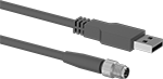 | |
4 Pole |
PVC Cord Insulation | |||||||||||||||
|---|---|---|---|---|---|---|---|---|---|---|---|---|---|---|---|
Housing Thread Size | No. of Poles | Face Dia. | Lg., ft. | USB Std. | Transmission Speed, Mbit/s | Shielding | Current, amp | Voltage, V DC | AWG | Cord OD | Temp. Range, ° F | Color | Each | ||
| M8 × 1 mm | 4 | 0.2" | 16 | 2.0 | 12 | Unshielded | 0.5 | 5 | 24 | 0.2" | -10 to 150 | Black | 5402N11 | 000000 | |
Metric Circular Cord Splitters
 |
Splitter |
Use fewer cords to send and receive signals. With these splitters, you can connect two sensors, switches, or devices to a single cord or port in a distribution block or IO-Link device.
Plug | Socket | Outer Jacket | |||||||||||
|---|---|---|---|---|---|---|---|---|---|---|---|---|---|
Coding | No. of Poles | Coding | No. of Poles | Lg., ft. | Voltage | Current, amp | Material | Color | Enclosure Rating | Each | |||
M8 Plug × Socket | |||||||||||||
Unshielded | |||||||||||||
| A | 3 | A | 3 | 1 | 50V AC/60V DC | 4 | PVC | Yellow | IP65, IP66K, IP67 | 4302N13 | 000000 | ||
| A | 4 | A | 3 | 1 | 50V AC/60V DC | 4 | PVC | Yellow | IP65, IP66K, IP67 | 4302N11 | 00000 | ||
| A | 4 | A | 4 | 1 | 50V AC/60V DC | 4 | PVC | Yellow | IP65, IP66K, IP67 | 4302N12 | 00000 | ||
Metric Circular Connector Caps
Sealed Power Supplies
 | 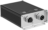 |
3-Pole M22 Plug Input and 4-Pole M22 Socket Output | 3-Pole M22 Plug Input and 5-Pole M22 Socket Output |
3-Pole M22 Plug | 4-Pole M22 Socket |
5-Pole M22 Socket |
Output | |||||||||||||||||
|---|---|---|---|---|---|---|---|---|---|---|---|---|---|---|---|---|---|
Voltage, V DC | Current, amp | Peak Current, amp | Peak Current Duration, sec. | Power, W | Max. Noise Peak-to-Peak, mV DC | No. of Output Connections per Circuit | Power Factor @ Voltage | Efficiency @ Voltage | Ht. | Wd. | Dp. | Enclosure Rating | Cannot Be Sold To | Each | |||
Single Phase—90-265V AC Input Voltage | |||||||||||||||||
3-Pole M22 Plug Input and 5-Pole M22 Socket Output | |||||||||||||||||
| 24 | 4 | 6 | 4 | 96 | 300 | 1 | 0.98 @ 230V AC | 91.7% @ 115V AC 92.4% @ 230V AC | 2.1" | 4.4" | 5.6" | IP67 | California, Vermont | 3580N15 | 0000000 | ||
| 24 | 8 | 12 | 4 | 96 | 300 | 1 | 0.95 @ 230V AC | 93% @ 115V AC 94.2% @ 230V AC | 2.1" | 4.4" | 6.9" | IP67 | California, Vermont | 3580N16 | 000000 | ||
Single Phase—100-240V AC Input Voltage | |||||||||||||||||
3-Pole M22 Plug Input and 4-Pole M22 Socket Output | |||||||||||||||||
| 24 | 3.8 | — | — | 100 | 50 | 1 | 0.9 @ 230V AC | 84% @ 115V AC 84% @ 230V AC | 1.9" | 7.2" | 4.9" | IP66, IP67 | California, Vermont | 3580N13 | 000000 | ||
| 24 | 7.6 | — | — | 100 | 50 | 4 | 0.9 @ 230V AC | 85% @ 115V AC 85% @ 130V AC | 3.4" | 7.2" | 4.9" | IP66, IP67 | California, Vermont | 3580N14 | 00000000 | ||
Micro M12 Ethernet Switches
 |
D-Code Ethernet Connection | 4-Pole M12 Plug |
5-Pole M12 Plug | 5-Pole M12 Socket |
From factory floors to railway systems, the sturdy connections on these switches connect cabled devices in tough environments. More rugged than the RJ45 ports on standard Ethernet switches, the M12 connectors are IP rated to seal out water and dust, and won't shake loose from vibration. Use them to send data between sensors, switches, servers, computers, and PLCs, or to connect devices to the Internet. Plug in your devices and they’ll be connected to your network, no further setup required. When not in use, protect connectors with an M12 electrical connector cap.
All switches are backward compatible, so they work in networks that meet the same or lower transmission speed. For example, a 100 Mbit/s transmission speed switch will work in a 10 Mbit/s network, but it will only run at 10 Mbit/s.
IP66 Enclosure Rating and IP67 Enclosure Rating—IP66 and IP67 rated switches withstand washdowns and temporary submersion. You’ll often find them mounted directly to machines or equipment in process control and outdoor communication applications.
IP69K Enclosure Rating—IP69K rated switches have the highest level of protection. They withstand high-pressure washdowns and steam cleaning. These switches are designed for harsh environments with regular exposure to water, so you’ll find them in manufacturing, food processing, and wastewater treatment facilities. You can also use them in areas exposed to rain or snow.
A Code—Switches with A-coded plugs only receive power—they can’t share power with another switch connected down the line.
Ethernet | Mounting | Power Connections | |||||||||||||
|---|---|---|---|---|---|---|---|---|---|---|---|---|---|---|---|
No. of Sockets | Coding | Transmission Speed, Mbit/s | Housing Material | Seal Material | Voltage, V DC | Fasteners Included | Hole Dia., mm | Temp. Range, ° F | Plug Type | Socket Type | Enclosure Rating | Each | |||
EtherNet/IP Communication Protocol, Modbus TCP/IP Communication Protocol | |||||||||||||||
Input, A Code | |||||||||||||||
| 6 | D | 10, 100 | Plastic | Fluoroelastomer | 8 to 32 | No | 5.3 | -10 to 155 | 4-Pole M12 | — | IP66, IP67 | 6207N11 | 0000000 | ||
| 6 | D | 10, 100 | Plastic | Fluoroelastomer | 8 to 32 | No | 5.3 | -10 to 155 | 4-Pole M12 | — | IP66, IP67, IP69K | 6207N15 | 000000 | ||
Outlet, Inlet | |||||||||||||||
| 6 | D | 10, 100 | Plastic | EPDM | 8 to 32 | No | 5.3 | -10 to 155 | 5-Pole M12 | 5-Pole M12 | IP66, IP67 | 6207N12 | 000000 | ||
| 6 | D | 10, 100 | Plastic | EPDM | 8 to 32 | No | 5.3 | -10 to 155 | 5-Pole M12 | 5-Pole M12 | IP66, IP67, IP69K | 6207N16 | 000000 | ||
PROFINET Communication Protocol | |||||||||||||||
Input, A Code | |||||||||||||||
| 6 | D | 10, 100 | Plastic | Fluoroelastomer | 8 to 32 | No | 5.3 | -10 to 155 | 4-Pole M12 | — | IP66, IP67 | 6207N13 | 000000 | ||
| 6 | D | 10, 100 | Plastic | Fluoroelastomer | 8 to 32 | No | 5.3 | -10 to 155 | 4-Pole M12 | — | IP66, IP67, IP69K | 6207N17 | 000000 | ||
Outlet, Inlet | |||||||||||||||
| 6 | D | 10, 100 | Plastic | EPDM | 8 to 32 | No | 5.3 | -10 to 155 | 5-Pole M12 | 5-Pole M12 | IP66, IP67 | 6207N14 | 000000 | ||
| 6 | D | 10, 100 | Plastic | EPDM | 8 to 32 | No | 5.3 | -10 to 155 | 5-Pole M12 | 5-Pole M12 | IP66, IP67, IP69K | 6207N18 | 000000 | ||
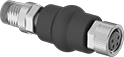
Metric Circular Cord Adapters
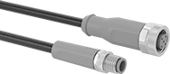 | 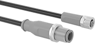 |
M8 Plug × M12 Socket | M12 Plug × M8 Socket |
Cords | Caps for Plugs | Caps for Sockets | |||||||||||||||
|---|---|---|---|---|---|---|---|---|---|---|---|---|---|---|---|---|---|
Plug | Socket | Outer Jacket | |||||||||||||||
Coding | No. of Poles | Coding | No. of Poles | Lg., ft. | Voltage | Current, amp | Material | Color | Enclosure Rating | Each | Each | Each | |||||
M8 Plug × M12 Socket | |||||||||||||||||
Unshielded | |||||||||||||||||
| A | 3 | A | 5 | 6 | 50V AC/60V DC | 3 | Polyurethane Rubber | Black | IP65, IP68, IP69K | 2453N15 | 000000 | ——— | 0 | 6897K74 | 000000 | ||
| A | 3 | A | 5 | 16 | 50V AC/60V DC | 3 | Polyurethane Rubber | Black | IP65, IP68, IP69K | 2453N16 | 00000 | ——— | 0 | 6897K74 | 00000 | ||
| A | 4 | A | 5 | 6 | 50V AC/60V DC | 3 | Polyurethane Rubber | Black | IP65, IP68, IP69K | 2453N17 | 00000 | ——— | 0 | 6897K74 | 00000 | ||
| A | 4 | A | 5 | 16 | 50V AC/60V DC | 3 | Polyurethane Rubber | Black | IP65, IP68, IP69K | 2453N18 | 00000 | ——— | 0 | 6897K74 | 00000 | ||
M12 Plug × M8 Socket | |||||||||||||||||
Unshielded | |||||||||||||||||
| A | 3 | A | 3 | 6 | 50V AC/60V DC | 3 | Polyurethane Rubber | Black | IP65, IP68, IP69K | 2453N11 | 00000 | 6897K73 | 000000 | ——— | 0 | ||
| A | 3 | A | 3 | 16 | 50V AC/60V DC | 3 | Polyurethane Rubber | Black | IP65, IP68, IP69K | 2453N12 | 00000 | 6897K73 | 00000 | ——— | 0 | ||
| A | 3 | A | 4 | 6 | 50V AC/60V DC | 3 | Polyurethane Rubber | Black | IP65, IP68, IP69K | 2453N13 | 00000 | 6897K73 | 00000 | ——— | 0 | ||
| A | 3 | A | 4 | 16 | 50V AC/60V DC | 3 | Polyurethane Rubber | Black | IP65, IP68, IP69K | 2453N14 | 00000 | 6897K73 | 00000 | ——— | 0 | ||
Device-Prioritizing Micro M12 Ethernet Switches
 |
4-Pole M12 Plug | 5-Pole M12 Plug |
4-Pole M12 Socket | 5-Pole M12 Socket |
Device-prioritizing Ethernet switches, also known as managed Ethernet switches, let you control which devices get priority speed on your network. For example, you can set it so that safety systems get all of the bandwidth they need while they are running, and all other devices on the network share what's left over. Easily set up these switches over the web or via command line interface. No software required.
Ethernet switches connect computers, sensors, and other devices to the same network so they can talk to each other, access the Internet, and provide you with real-time diagnostics. These switches have port mirroring, which duplicates data from one network port to another—this lets you keep an eye on network traffic and troubleshoot performance issues. They are backward compatible, so they'll work in networks below their rated transmission speed. For example, a 100 Mbit/s switch will work in a 10 Mbit/s network, but it will only run at 10 Mbit/s.
M12 connections instead of typical RJ45 keep out contaminants and won’t come loose from vibration.
D—D-coded connectors are used for Ethernet rated up to Category 5 or 100 Mbps.
X—X-coded connectors are used for high-speed Ethernet with data transfer rates up to 1 Gb/s.
5-Pole M12—Switches with a 5-pole power plug have a ground pin.
IEEE 802.1q—These switches use the IEEE 802.1q standard for VLAN (Virtual Local Area Network). VLAN increases security, reliability, and efficiency by clustering devices on the network into groups and limiting when and how devices can communicate outside of their group.
Ethernet | Mounting | Power Connections | |||||||||||||||||||
|---|---|---|---|---|---|---|---|---|---|---|---|---|---|---|---|---|---|---|---|---|---|
No. of Sockets | Coding | Connection | Transmission Speed | Ht. | Wd. | Dp. | Housing Material | Voltage, V DC | Fasteners Included | Hole Dia., mm | Temp. Range, ° F | Plug Type | Socket Type | Coding | Certification | Specs. Met | Enclosure Rating | Each | |||
EtherNet/IP Communication Protocol | |||||||||||||||||||||
| 10 | D | M12 | 10 Mbit/s, 100 Mbit/s | 8 7/8" | 2 1/2" | 1 7/16" | Metal | 9 to 30 | No | 7.5 | -10 to 130 | 4-Pole M12 | 4-Pole M12 | L | UL Listed, C-UL Listed, CE Marked | IEEE 802.1q | IP67 | 6655N11 | 000000000 | ||
| 10 | D | M12 | 10 Mbit/s, 100 Mbit/s | 8 7/8" | 2 1/2" | 1 7/16" | Metal | 9 to 30 | No | 7.5 | -10 to 130 | 5-Pole M12 | 5-Pole M12 | L | UL Listed, C-UL Listed, CE Marked | IEEE 802.1q | IP67 | 6655N21 | 00000000 | ||
| 10 | X | M12 | 10 Mbit/s, 100 Mbit/s, 1 Gbit/s | 8 7/8" | 2 1/2" | 1 7/16" | Metal | 9 to 30 | No | 7.5 | -10 to 110 | 4-Pole M12 | 4-Pole M12 | L | UL Listed, C-UL Listed, CE Marked | IEEE 802.1q | IP67 | 6655N15 | 00000000 | ||
| 10 | X | M12 | 10 Mbit/s, 100 Mbit/s, 1 Gbit/s | 8 7/8" | 2 1/2" | 1 7/16" | Metal | 9 to 30 | No | 7.5 | -10 to 110 | 5-Pole M12 | 5-Pole M12 | L | UL Listed, C-UL Listed, CE Marked | IEEE 802.1q | IP67 | 6655N25 | 00000000 | ||
| 8 2 | D X | M12 | 10 Mbit/s, 100 Mbit/s 10 Mbit/s, 100 Mbit/s, 1 Gbit/s | 8 7/8" | 2 1/2" | 1 7/16" | Metal | 9 to 30 | No | 7.5 | -10 to 130 | 4-Pole M12 | 4-Pole M12 | L | UL Listed, C-UL Listed, CE Marked | IEEE 802.1q | IP67 | 6655N13 | 00000000 | ||
| 8 2 | D X | M12 | 10 Mbit/s, 100 Mbit/s 10 Mbit/s, 100 Mbit/s, 1 Gbit/s | 8 7/8" | 2 1/2" | 1 7/16" | Metal | 9 to 30 | No | 7.5 | -10 to 130 | 5-Pole M12 | 5-Pole M12 | L | UL Listed, C-UL Listed, CE Marked | IEEE 802.1q | IP67 | 6655N23 | 00000000 | ||
PROFINET Communication Protocol | |||||||||||||||||||||
| 10 | D | M12 | 10 Mbit/s, 100 Mbit/s | 8 7/8" | 2 1/2" | 1 7/16" | Metal | 9 to 30 | No | 7.5 | -10 to 130 | 4-Pole M12 | 4-Pole M12 | L | UL Listed, C-UL Listed, CE Marked | IEEE 802.1q | IP67 | 6655N12 | 00000000 | ||
| 10 | D | M12 | 10 Mbit/s, 100 Mbit/s | 8 7/8" | 2 1/2" | 1 7/16" | Metal | 9 to 30 | No | 7.5 | -10 to 130 | 5-Pole M12 | 5-Pole M12 | L | UL Listed, C-UL Listed, CE Marked | IEEE 802.1q | IP67 | 6655N22 | 00000000 | ||
| 10 | X | M12 | 10 Mbit/s, 100 Mbit/s, 1 Gbit/s | 8 7/8" | 2 1/2" | 1 7/16" | Metal | 9 to 30 | No | 7.5 | -10 to 110 | 4-Pole M12 | 4-Pole M12 | L | UL Listed, C-UL Listed, CE Marked | IEEE 802.1q | IP67 | 6655N16 | 00000000 | ||
| 10 | X | M12 | 10 Mbit/s, 100 Mbit/s, 1 Gbit/s | 8 7/8" | 2 1/2" | 1 7/16" | Metal | 9 to 30 | No | 7.5 | -10 to 110 | 5-Pole M12 | 5-Pole M12 | L | UL Listed, C-UL Listed, CE Marked | IEEE 802.1q | IP67 | 6655N26 | 00000000 | ||
| 8 2 | D X | M12 | 10 Mbit/s, 100 Mbit/s 10 Mbit/s, 100 Mbit/s, 1 Gbit/s | 8 7/8" | 2 1/2" | 1 7/16" | Metal | 9 to 30 | No | 7.5 | -10 to 130 | 4-Pole M12 | 4-Pole M12 | L | UL Listed, C-UL Listed, CE Marked | IEEE 802.1q | IP67 | 6655N14 | 00000000 | ||
| 8 2 | D X | M12 | 10 Mbit/s, 100 Mbit/s 10 Mbit/s, 100 Mbit/s, 1 Gbit/s | 8 7/8" | 2 1/2" | 1 7/16" | Metal | 9 to 30 | No | 7.5 | -10 to 130 | 5-Pole M12 | 5-Pole M12 | L | UL Listed, C-UL Listed, CE Marked | IEEE 802.1q | IP67 | 6655N24 | 00000000 | ||
