



























Filter by
Machine Taper Number


Thread Size

For Use With
Projection
DFARS Specialty Metals
Export Control Classification Number (ECCN)


Shank Thread Size
Shank Thread Pitch
Taper Tolerance
Bit Shank Size
Manufacturer Equivalent Model Number
Balance Quality Grade
Shank Size
Finish
BT Taper Compensating Tap Collet Holders
 |
 |
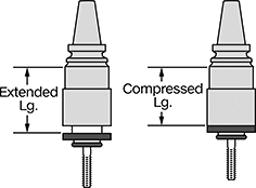 |  |
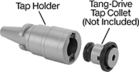
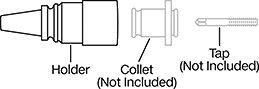
Reduce stress on taps to produce clean, accurate threads. These holders work with BT taper CNC machines that don’t support rigid tapping. Also called tension and compression tap holders, they compress as the tap enters material and extend as it backs out, compensating for small spindle and feed rate mismatches. Not only does this protect the tap but also the threads you just cut. They’re often used when tapping through and blind holes with spiral-point and spiral-flute taps.
Their hardened steel shank resists wear. It’s also precision ground to the industry standard AT3 tolerance for a secure fit that minimizes runout in your machine spindle. They meet JIS standards for BT spindles to ensure compatibility. They have a threaded hole that accepts retention knobs, so they connect to your machine’s drawbar system.
Use these holders with tang-drive quick-change tap collets (also known as Bilz-style tap adapters) to swap taps in seconds and limit machine downtime. They are not compatible with ball-drive quick-change tap collets.
For the best performance, select a quick-change collet size that places your tap near the middle of the listed tap size range.
For Tap | Lg. | |||||||||||||
|---|---|---|---|---|---|---|---|---|---|---|---|---|---|---|
For Quick-Change Tap Collet Size | Size | Pipe Size | Extended | Compressed | Projection | Body Dia. | Total Indicated Runout (TIR) Accuracy | Material | JIS Specification | For Drive Type | Each | |||
BT 40 Taper | ||||||||||||||
| ANSI 1 | No. 0 to 9/16" M1.6 to M14 | 1/8 | 3.03" | 2.33" | 2 5/8" | 3/4" | 0.0001" | Hardened Steel | JIS B 6339 | Tang | 8908N13 | 0000000 | ||
| ANSI 2 | 5/16" to 7/8" M7 to M22 | 1/4 to 1/2 | 4.25" | 3.07" | 3 5/8" | 1 1/4" | 0.0001" | Hardened Steel | JIS B 6339 | Tang | 8908N14 | 000000 | ||
| ANSI 3 | 1/2" to 1 3/8" M12 to M33 | 3/8 to 1 | 6.37" | 4.49" | 5 3/8" | 1 7/8" | 0.0001" | Hardened Steel | JIS B 6339 | Tang | 8908N15 | 000000 | ||
BT Taper Rigid Tap Collet Holders
 |
 |
|
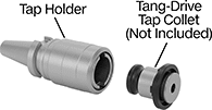
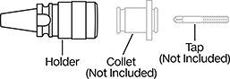
Hold quick-change tap collets on BT taper CNC machines capable of rigid tapping. These holders are rigid, so they move your tap in perfect sync with your machine's spindle speed and feed rate without any flex or compensation.
The hardened steel shank resists wear. It’s also precision ground to the industry standard AT3 tolerance for a secure fit that minimizes runout in your machine spindle. They meet JIS standards for BT spindles to ensure compatibility. They have a threaded hole that accepts retention knobs, so they connect to your machine’s drawbar system.
Use these holders with tang-drive quick-change tap collets (also known as Bilz-style tap adapters) to swap taps in seconds and limit machine downtime. They are not compatible with ball-drive quick-change tap collets or quick-change tap collets with torque control.
For the best performance, select a quick-change collet size that places your tap near the middle of the listed tap size range.
For Tap | ||||||||||||
|---|---|---|---|---|---|---|---|---|---|---|---|---|
For Quick-Change Tap Collet Size | Size | Pipe Size | Projection | Body Dia. | Total Indicated Runout (TIR) Accuracy | Material | JIS Specification | For Drive Type | Each | |||
BT 40 Taper | ||||||||||||
| ANSI 1 | No. 0 to 9/16" M1.6 to M14 | 1/8 | 2 1/2" | 1 1/4" | 0.0001" | Hardened Steel | JIS B 6339 | Tang | 8910N13 | 0000000 | ||
| ANSI 2 | 5/16" to 7/8" M7 to M22 | 1/4 to 1/2 | 3 1/2" | 2" | 0.0001" | Hardened Steel | JIS B 6339 | Tang | 8910N14 | 000000 | ||
| ANSI 3 | 1/2" to 1 3/8" M12 to M33 | 3/8 to 1 | 4 1/2" | 2 7/8" | 0.0001" | Hardened Steel | JIS B 6339 | Tang | 8910N15 | 000000 | ||
BT Taper Collet Chucks
BT 40 Machine Taper
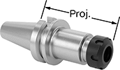 |
Collet Stop Screw—Chucks with a collet stop screw set the tool depth in the chuck for consistent, repeatable performance when you change tools.
RFID Chip Hole—Chucks with an RFID chip hole can hold a small RFID tag for automatic tool identification and tracking.
Milling Machine Collet Chucks | Wrenches | Replacement Nuts | ||||||||||||||
|---|---|---|---|---|---|---|---|---|---|---|---|---|---|---|---|---|
For Collet Type | For Bit Shank Size | Projection | Total Indicated Runout (TIR) Accuracy | Collet Nut Type | Coolant Delivery Type | Features | Specs. Met | JIS Specification | Each | Each | Each | |||||
2.5 mm/s @ 25,000 rpm | ||||||||||||||||
Hardened Chrome-Moly Steel | ||||||||||||||||
| ER-16 | 0.019" to 0.406" | 2.76" (70 mm) | 0.0001" | Coated Hex Nut | Through Bore | RFID Chip Hole | ISO 7388-2 | JIS B 6339 | 9483N18 | 0000000 | 3215A441 | 000000 | 9615N31 | 000000 | ||
| ER-16 | 0.019" to 0.406" | 3.94" (100 mm) | 0.0001" | Coated Hex Nut | Through Bore | RFID Chip Hole | ISO 7388-2 | JIS B 6339 | 9483N19 | 000000 | 3215A441 | 00000 | 9615N31 | 00000 | ||
| ER-20 | 0.039" to 0.551" | 2.76" (70 mm) | 0.0001" | Coated Hex Nut | Through Bore | RFID Chip Hole | ISO 7388-2 | JIS B 6339 | 9483N21 | 000000 | 1721N15 | 00000 | 9615N32 | 00000 | ||
| ER-20 | 0.039" to 0.551" | 3.94" (100 mm) | 0.0001" | Coated Hex Nut | Through Bore | RFID Chip Hole | ISO 7388-2 | JIS B 6339 | 9483N22 | 000000 | 1721N15 | 00000 | 9615N32 | 00000 | ||
| ER-25 | 0.039" to 0.629" | 2.76" (70 mm) | 0.0001" | Coated Slotted Nut | Through Bore | RFID Chip Hole | ISO 7388-2 | JIS B 6339 | 9483N23 | 000000 | 5699N128 | 00000 | 9615N35 | 00000 | ||
| ER-25 | 0.039" to 0.629" | 3.94" (100 mm) | 0.0001" | Coated Slotted Nut | Through Bore | RFID Chip Hole | ISO 7388-2 | JIS B 6339 | 9483N24 | 000000 | 5699N128 | 00000 | 9615N35 | 00000 | ||
| ER-32 | 0.078" to 0.787" | 2.76" (70 mm) | 0.0001" | Coated Slotted Nut | Through Bore | RFID Chip Hole | ISO 7388-2 | JIS B 6339 | 9483N25 | 000000 | 3321A32 | 00000 | 9615N36 | 00000 | ||
| ER-32 | 0.078" to 0.787" | 3.94" (100 mm) | 0.0001" | Coated Slotted Nut | Through Bore | RFID Chip Hole | ISO 7388-2 | JIS B 6339 | 9483N26 | 000000 | 3321A32 | 00000 | 9615N36 | 00000 | ||
| ER-40 | 0.118" to 1.024" | 3.15" (80 mm) | 0.0001" | Coated Slotted Nut | Through Bore | RFID Chip Hole | ISO 7388-2 | JIS B 6339 | 9483N27 | 000000 | 32605A95 | 00000 | 9615N37 | 00000 | ||
6.3 mm/s @ 15,000 rpm | ||||||||||||||||
Hardened Nickel Chrome-Moly Steel | ||||||||||||||||
| ER-11 | 0.019" to 0.275" | 3" | 0.0001" | Hex Nut | Flange Entry, Through Bore | Collet Stop Screw | — | JIS B 6339 | 9483N28 | 00000 | 5699N127 | 00000 | 9502N17 | 00000 | ||
| ER-16 | 0.019" to 0.406" | 3" | 0.0001" | Hex Nut | Flange Entry, Through Bore | Collet Stop Screw | — | JIS B 6339 | 9483N29 | 00000 | 3215A441 | 00000 | 9502N18 | 00000 | ||
| ER-16 | 0.019" to 0.406" | 6" | 0.0001" | Hex Nut | Flange Entry, Through Bore | Collet Stop Screw | — | JIS B 6339 | 9483N31 | 000000 | 3215A441 | 00000 | 9502N18 | 00000 | ||
| ER-20 | 0.039" to 0.551" | 2.2" | 0.0001" | Hex Nut | Flange Entry, Through Bore | Collet Stop Screw | — | JIS B 6339 | 9483N32 | 00000 | 1721N15 | 00000 | 9502N19 | 00000 | ||
| ER-20 | 0.039" to 0.551" | 4" | 0.0001" | Hex Nut | Flange Entry, Through Bore | Collet Stop Screw | — | JIS B 6339 | 9483N33 | 000000 | 1721N15 | 00000 | 9502N19 | 00000 | ||
| ER-25 | 0.039" to 0.629" | 2.5" | 0.0001" | Slotted Nut | Flange Entry, Through Bore | Collet Stop Screw | — | JIS B 6339 | 9483N34 | 00000 | 5699N128 | 00000 | 9502N21 | 00000 | ||
| ER-25 | 0.039" to 0.629" | 4" | 0.0001" | Slotted Nut | Flange Entry, Through Bore | Collet Stop Screw | — | JIS B 6339 | 9483N35 | 000000 | 5699N128 | 00000 | 9502N21 | 00000 | ||
| ER-32 | 0.078" to 0.787" | 2.5" | 0.0001" | Slotted Nut | Flange Entry, Through Bore | Collet Stop Screw | — | JIS B 6339 | 9483N36 | 00000 | 3321A32 | 00000 | 9502N22 | 00000 | ||
| ER-32 | 0.078" to 0.787" | 4" | 0.0001" | Slotted Nut | Flange Entry, Through Bore | Collet Stop Screw | — | JIS B 6339 | 9483N37 | 000000 | 3321A32 | 00000 | 9502N22 | 00000 | ||
| ER-32 | 0.078" to 0.787" | 6" | 0.0001" | Slotted Nut | Flange Entry, Through Bore | Collet Stop Screw | — | JIS B 6339 | 9483N38 | 000000 | 3321A32 | 00000 | 9502N22 | 00000 | ||
| ER-40 | 0.118" to 1.024" | 4" | 0.0001" | Slotted Nut | Flange Entry, Through Bore | Collet Stop Screw | — | JIS B 6339 | 9483N39 | 000000 | 32605A95 | 00000 | 9502N23 | 00000 | ||
Drill Chucks with BT Taper Integral Arbor
 |  |
Keyless Chuck | Keyed Chuck |
Limit runout and slippage under heavy cutting forces from CNC machines. These chucks have an integrated arbor for a one-piece design that makes them more accurate and compact than chucks with a separate arbor. Made of hardened steel, they resist wear from repeated use. Their shank is precision ground to the industry standard AT3 tolerance for a tight fit in your spindle. They meet JIS standards for compatibility across machines with BT spindles. They have a threaded hole that accepts retention knobs, so they connect to your machine’s drawbar system.
Keyless Chuck—Keyless chucks let you swap bits in and out with a quick twist of the sleeve. As torque increases, their grip will tighten. These chucks only tighten in the clockwise direction, so they may loosen under heavy reverse loads, such as during left-hand drilling. They’re balanced to grade 6.3, so they’re good for most drilling tasks.
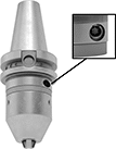
Keyed Chuck—Keyed chucks use a worm-and-gear design to deliver exceptional grip on bits for the highest torque and accuracy when drilling in hard materials. They're so strong they can even be used for light duty milling in soft materials such as aluminum. Use their Torx key to tighten and loosen the chuck. Balanced to grade 2.5, they vibrate 60% less than chucks balanced to 6.3 for longer life under heavy use and high speeds. You can route coolant through these chucks to extend the life of your bit and clear chips. For automatic tool identification and tracking, they have a hole for a small RFID tag.
Machine Taper No. | For Bit Shank Size | Balance Quality Grade | Total Indicated Runout (TIR) Accuracy | Jaw Material | Body Material | Projection | Max. Body Dia. | For Tool Drive Direction | Features | Includes | Certificate Type | JIS Specification | Each | |||
|---|---|---|---|---|---|---|---|---|---|---|---|---|---|---|---|---|
Keyless Chuck | ||||||||||||||||
| BT 40 | 0" to 5/16" 0 mm to 8 mm | 6.3 mm/s @ 7,000 rpm | 0.0016" | Hardened Steel | Hardened Steel | 3 9/32" | 1.52" | Clockwise | Wrench Flats | — | — | JIS B 6339 | 9786N12 | 0000000 | ||
Keyed Chuck | ||||||||||||||||
| BT 40 | 1/32" to 5/8" 1 mm to 16 mm | 2.5 mm/s @ 25,000 rpm | 0.0008" | Hardened Steel | Hardened Steel | 3 3/4" | 1.97" | Clockwise, Counterclockwise | Through-Bore Coolant, RFID Tag Hole | Key | Accuracy Certificate | JIS B 6339 | 9786N14 | 000000 | ||
BT Taper Retention Knobs
 |  |
Knob with Pilot |
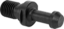
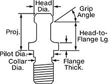
Lock tool holders in place on CNC machines with a BT taper spindle. All meet industrial standards for tensile and shear strength. These knobs are also known as pull studs. They have a pilot, which ensures precise alignment between the tool holder and spindle, reducing vibration and runout. To ensure compatibility with your machine, compare the features on these knobs, such as the pilot design, to those on your current knob. If you want to upgrade a standard knob to one with a pilot, confirm that the pilot diameter is small enough to fit in your tool holder without touching the inner walls where the knob seats.
Use a torque wrench with a retention knob socket or a changeable-head torque wrench to tighten them.
Grip Angle—Grip angle is the sloped part of the knob that the machine grips to secure the tool holder. A 15˚ grip angle is sometimes referred to as a 75˚ grip angle. A 30˚ grip angle is sometimes referred to as a 60˚ grip angle.
Grip Angle | Projection | Head Dia. | Pilot Dia. | Collar Dia. | Head-to-Flange Lg. | Flange Thk. | Torque Range, ft·lbf | Mfr. | Mfr. Model No. | Mfr. Equiv. Model No. | Specs. Met | JIS Specification | Each | |||
|---|---|---|---|---|---|---|---|---|---|---|---|---|---|---|---|---|
BT 40 Machine Taper | ||||||||||||||||
M16 × 2 mm | ||||||||||||||||
| 15° | 1.141" | 0.746" | 0.669" | 0.505" | 0.905" | 0.275" | 45 to 55 | T.J. Davies | PS-444X15 | 40PH, 329-12, 4020NTRK, 21101, 32912, B40-1500, HPS-805, PS-805, RS4M-0205 | — | JIS B 6339 | 9485N17 | 000000 | ||
| 30° | 1.378" | 0.588" | 0.669" | 0.505" | 1.1" | 0.236" | 45 to 55 | T.J. Davies | PS-444X60 | 311-13A, 4004TRK, 17808, 31113A, B40-6000, HPS-2, RB4M-0002 | — | JIS B 6339 | 9485N22 | 00000 | ||
| 45° | 0.752" | 0.74" | 0.669" | 0.505" | 0.552" | 0.236" | 45 to 55 | T.J. Davies | PS-477 | 111-26, 11126, 21105, B40-FADAL, F40TRK, RS4M-0115 | ASME B5.50, ISO 7388-3 | JIS B 6339 | 9485N18 | 00000 | ||
| 45° | 1.378" | 0.588" | 0.669" | 0.505" | 1.1" | 0.236" | 45 to 55 | T.J. Davies | PS-444X45 | 311-13, 4003TRK, 17803, 31113, B50-4500, HPS-1, P40T-1, PS-70, RB4M-0001 | — | JIS B 6339 | 9485N19 | 00000 | ||
| 45° | 1.546" | 0.592" | 0.669" | 0.505" | 1.25" | 0.187" | 45 to 55 | T.J. Davies | PS-554 | 171-26, 17126, 21116 | ASME B5.50, ISO 7388-3 | JIS B 6339 | 9485N21 | 00000 | ||
| 90° | 1.378" | 0.588" | 0.669" | 0.505" | 1.1" | 0.236" | 45 to 55 | T.J. Davies | PS-444X90 | 311-13B, 4002TRK, 17814, 31113B, B40-9000, HPS-08, POM40F, POM40MG, RB4M-0003 | — | JIS B 6339 | 9485N23 | 00000 | ||
BT Taper Retention Knobs with Coolant Hole
 |  |
Knob with Pilot |
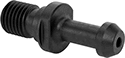
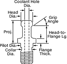
Lock tool holders in place on CNC machines with a through-spindle coolant (TSC) system. They fit machines with a BT taper spindle. All meet industrial standards for tensile and shear strength. Also known as pull studs. These knobs have a pilot, which ensures precise alignment between the tool holder and spindle, reducing vibration and runout. To ensure compatibility with your machine, compare the features on these knobs, such as the location of O-ring seals and the pilot design, to those on your current knob. To upgrade a standard knob to one with a pilot, confirm that the pilot diameter is small enough to fit in your tool holder without touching the inner walls where the knob seats.
Use a torque wrench with a retention knob socket or a changeable-head torque wrench to tighten them.
Flange O-Ring Included—Knobs with flange O-rings block external coolant from entering your machine spindle. Match the O-ring placement and style to your current setup to ensure optimal sealing and performance.
Grip Angle—Grip angle is the sloped part of the knob that the machine grips to secure the tool holder. A 15˚ grip angle is sometimes referred to as a 75˚ grip angle. A 30˚ grip angle is sometimes referred to as a 60˚ grip angle.
Grip Angle | Projection | Head Dia. | Coolant Hole Diameter | Pilot Dia. | Collar Dia. | Head-to-Flange Lg. | Flange Thk. | Torque Range, ft·lbf | O-Rings Included | Mfr. | Mfr. Model No. | Mfr. Equiv. Model No. | Specs. Met | JIS Specification | Each | |||
|---|---|---|---|---|---|---|---|---|---|---|---|---|---|---|---|---|---|---|
BT 40 Machine Taper | ||||||||||||||||||
M16 × 2 mm | ||||||||||||||||||
| 15° | 1.136" | 0.746" | 0.264" | 0.669" | 0.505" | 0.9" | 0.157" | 45 to 55 | — | T.J. Davies | PSC-480X15 | 711-22, 21130-C, 71122, DIN40ATRK, RS4M-0114-C | ISO 7388-3 | JIS B 6339 | 9487N16 | 000000 | ||
| 15° | 1.136" | 0.746" | 0.264" | 0.669" | 0.505" | 0.9" | 0.157" | 45 to 55 | Flange O-Ring, Head O-Ring in Coolant Hole | T.J. Davies | PSCO-480X15A | B40-1500 Mori EU, HPS-366E-1 | ISO 7388-3 | JIS B 6339 | 9487N15 | 00000 | ||
| 15° | 1.141" | 0.746" | 0.264" | 0.669" | 0.505" | 0.905" | 0.275" | 45 to 55 | — | T.J. Davies | PSC-444X15 | 40PH, 329-13, 21101-C, 32913, B40-1500 H, HPS-806-1, RS4M-0205-C | ISO 7388-3 | JIS B 6339 | 9487N17 | 00000 | ||
| 30° | 1.378" | 0.588" | 0.166" | 0.669" | 0.505" | 1.1" | 0.236" | 45 to 55 | — | T.J. Davies | PSC-444X60 | 311-13E, 4004TRKC, 17820, 31113E, B40-6000 H, HPS-2 C, RB4M-0002-C | — | JIS B 6339 | 9487N22 | 00000 | ||
| 45° | 0.752" | 0.74" | 0.264" | 0.669" | 0.505" | 0.552" | 0.120" | 45 to 55 | — | T.J. Davies | PSC-479 | 312-25, 21129-C, 31225, HPS-G51, MZ40TRKC, PS-G51 | ASME B5.50, ISO 7388-3 | JIS B 6339 | 9487N18 | 00000 | ||
| 45° | 0.752" | 0.74" | 0.264" | 0.669" | 0.505" | 0.552" | 0.236" | 45 to 55 | — | T.J. Davies | PSC-477 | 111-26A, 11126A, 21105-C, B40-FADAL C, F40TRKC, RS4M-0115-C | ASME B5.50, ISO 7388-3 | JIS B 6339 | 9487N19 | 00000 | ||
| 45° | 1.378" | 0.588" | 0.166" | 0.669" | 0.505" | 1.1" | 0.236" | 45 to 55 | — | T.J. Davies | PSC-444X45 | 311-13D, 4003TRKC, 17818, 31113D, B40-4500 H, HPS-1C, RB4M-0001-C | — | JIS B 6339 | 9487N21 | 00000 | ||
| 90° | 1.378" | 0.588" | 0.166" | 0.669" | 0.505" | 1.1" | 0.236" | 45 to 55 | — | T.J. Davies | PSC-444X90 | 311-13F, 4002TRKC, 17822, 31113F, B40-9000 H, HPS-08 C, RB4M-0003-C | — | JIS B 6339 | 9487N23 | 00000 | ||
