


Filter by
Electrical Connection
Wire Connection

Electrical Connector Component
Export Control Classification Number (ECCN)
DFARS Specialty Metals
Thermocouple Connectors
 |  | ||
Flat-Pin Mini Male Connector | Flat-Pin Mini Female Connector | Round-Pin Male Connector | Round-Pin Female Connector |
Material | Male Connection | Female Connection | |||||||||
|---|---|---|---|---|---|---|---|---|---|---|---|
Thermocouple Type | For Max. Wire Ga. | Color | Distance Between Pins | Body | Contact | Each | Each | ||||
Flat-Pin Mini Thermocouple Connectors—400° F Max. Temp. | |||||||||||
Screw-Terminal Wire Connection | |||||||||||
| B | 24 | White | 0.313" | Plastic | Copper | 3869K117 | 00000 | 3869K125 | 00000 | ||
| C | 23 | Red | 0.313" | Plastic | Tungsten | 3869K143 | 00000 | 3869K144 | 00000 | ||
| E | 24 | Purple | 0.313" | Plastic | Nickel | 3869K113 | 0000 | 3869K121 | 0000 | ||
| J | 24 | Black | 0.313" | Plastic | Iron | 3869K33 | 0000 | ——— | 0 | ||
| K | 24 | Yellow | 0.313" | Plastic | Nickel | 3869K35 | 0000 | ——— | 0 | ||
| N | 24 | Orange | 0.313" | Plastic | Nickel | 3869K112 | 0000 | 3869K119 | 0000 | ||
| R | 24 | Green | 0.313" | Plastic | Copper | 3869K114 | 0000 | 3869K122 | 0000 | ||
| S | 24 | Green | 0.313" | Plastic | Copper | 3869K115 | 0000 | 3869K123 | 0000 | ||
| T | 24 | Blue | 0.313" | Plastic | Copper | 3869K37 | 0000 | ——— | 0 | ||
| U | 24 | White | 0.313" | Plastic | Tungsten | 3869K116 | 0000 | 3869K124 | 0000 | ||
Flat-Pin Mini Thermocouple Connectors—800° F Max. Temp. | |||||||||||
Screw-Terminal Wire Connection | |||||||||||
| J | 24 | Red | 0.313" | Plastic | Iron | 3869K41 | 0000 | ——— | 0 | ||
| K | 24 | Red | 0.313" | Plastic | Nickel | 3869K42 | 0000 | ——— | 0 | ||
| T | 24 | Red | 0.313" | Plastic | Copper | 3869K43 | 0000 | ——— | 0 | ||
Round-Pin Thermocouple Connectors—400° F Max. Temp. | |||||||||||
Screw-Terminal Wire Connection | |||||||||||
| B | 14 | White | 0.438" | Plastic | Copper | 3869K133 | 0000 | 3869K141 | 0000 | ||
| C | 14 | Brown | 0.438" | Plastic | Tungsten | 3869K134 | 00000 | 3869K142 | 00000 | ||
| E | 14 | Purple | 0.438" | Plastic | Nickel | 3869K128 | 0000 | 3869K136 | 0000 | ||
| N | 14 | Orange | 0.438" | Plastic | Nickel | 3869K127 | 0000 | 3869K135 | 0000 | ||
| R | 14 | Green | 0.438" | Plastic | Copper | 3869K129 | 0000 | 3869K137 | 0000 | ||
| S | 14 | Green | 0.438" | Plastic | Copper | 3869K131 | 0000 | 3869K138 | 0000 | ||
| U | 14 | White | 0.438" | Plastic | Tungsten | 3869K132 | 0000 | 3869K139 | 0000 | ||
Mini Splitters
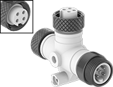 |
Plug × Socket × Socket |
2 Poles | 3 Poles |
4 Poles | 5 Poles |
6 Poles |
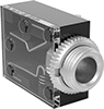
Simplify wiring and reduce the number of cords in your automation setup. These splitters create a branch off a main cord or connect multiple devices with a mini connection to a single port in a junction box or I/O module. A threaded housing securely mates with other mini connectors to keep out contaminants and won’t come loose from shaking or vibration. They have a standard pole layout and housing thread size to reduce the chance you’ll mis-mate connectors.
Tee Splitters
Plug | Sockets | ||||||||||||||
|---|---|---|---|---|---|---|---|---|---|---|---|---|---|---|---|
No. of Poles | Face Dia. | Housing Thread Size | No. of Poles | Face Dia. | Housing Thread Size | Voltage | Current, amp | Housing Material | Temp. Range, ° F | Enclosure Rating | Certification | Each | |||
Plug (UNS External Thread) × Socket (UNS Internal Thread) | |||||||||||||||
| 2 | 0.55" | 7/8"-16 | 2 | 0.55" | 7/8"-16 | 600V AC/600V DC | 13 | Polyurethane Rubber | 0 to 175 | IP68, NEMA 6P | UL Recognized Component, CSA Certified | 5032N11 | 000000 | ||
| 3 | 0.55" | 7/8"-16 | 3 | 0.55" | 7/8"-16 | 600V AC/600V DC | 13 | Polyurethane Rubber | 0 to 175 | IP68, NEMA 6P | UL Recognized Component, CSA Certified | 5032N12 | 00000 | ||
| 4 | 0.55" | 7/8"-16 | 4 | 0.55" | 7/8"-16 | 600V AC/600V DC | 10 | Polyurethane Rubber | 0 to 175 | IP68, NEMA 6P | UL Recognized Component, CSA Certified | 5032N13 | 00000 | ||
| 5 | 0.55" | 7/8"-16 | 5 | 0.55" | 7/8"-16 | 600V AC/600V DC | 8 | Polyurethane Rubber | 0 to 175 | IP68, NEMA 6P | UL Recognized Component, CSA Certified | 5032N14 | 000000 | ||
| 6 | 0.55" | 7/8"-16 | 6 | 0.55" | 7/8"-16 | 600V AC/600V DC | 8 | Polyurethane Rubber | 0 to 175 | IP68, NEMA 6P | UL Recognized Component, CSA Certified | 5032N15 | 000000 | ||


 |
Thread | ||||||||
|---|---|---|---|---|---|---|---|---|
Size | Type | Material | Temp. Range, ° F | Electrical Connector Component | Each | |||
External Thread | ||||||||
| 7/8"-16 | UNS | Aluminum | -4 to 190 | Adapter | 69005K51 | 00000 | ||
Audio Equipment Connectors
Male Straight Plugs
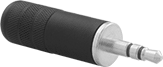 | |
1/4" Pin Dia. | 3.5 mm Pin Dia. |
Audio Connection Channel | Pin Dia. | No. of Poles | Voltage | Current, amp | Wire Connection Method | For Wire Ga. | Housing Material | OD | Lg. | Temp. Range, ° F | Each | |||
|---|---|---|---|---|---|---|---|---|---|---|---|---|---|---|
Push-In Housing | ||||||||||||||
| Stereo | 1/4" | 3 | 48V DC/48V AC | 7 | Solder | 14 | Nickel-Plated Brass | 0.47" | 2.47" | -40 to 185 | 1760N25 | 000000 | ||
| Stereo | 3.5 mm | 3 | 250V AC/140V DC | 4 | Solder | 16 | Anodized Aluminum | 0.41" | 1.71" | 0 to 145 | 1760N32 | 00000 | ||
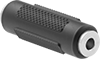
Male 90° Elbow Plugs
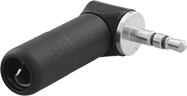 | |
1/4" Pin Dia. | 3.5 mm Pin Dia. |
Audio Connection Channel | Pin Dia. | No. of Poles | Voltage | Current, amp | Wire Connection Method | For Wire Ga. | Housing Material | OD | Lg. | Temp. Range, ° F | Each | |||
|---|---|---|---|---|---|---|---|---|---|---|---|---|---|---|
Push-In Housing | ||||||||||||||
| Stereo | 1/4" | 3 | 48V DC/48V AC | 7 | Solder | 14 | Nickel-Plated Brass | 0.5" | 1.83" | -40 to 185 | 1760N27 | 000000 | ||
| Stereo | 3.5 mm | 3 | 250V AC/140V DC | 4 | Solder | 16 | Anodized Aluminum | 0.41" | 1.02" | 0 to 145 | 1760N33 | 00000 | ||
Female Straight Sockets
Push In |
Audio Connection Channel | For Pin Dia., mm | No. of Poles | Voltage | Current, amp | Wire Connection Method | For Wire Ga. | Housing Material | Sleeve Material | OD | Lg. | Temp. Range, ° F | Each | |||
|---|---|---|---|---|---|---|---|---|---|---|---|---|---|---|---|
Push-In Housing | |||||||||||||||
| Stereo | 3.5 | 2 | 250V AC/140V DC | 4 | Solder | 16 | Nickel-Plated Brass | Nickel-Plated Brass | 0.41" | 1.81" | -40 to 85 | 1760N34 | 000000 | ||
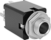
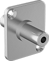
Female Panel-Mount Straight Receptacles
 |
With Plug Retaining Spring |
Off (Normally Open) Circuit Position—Receptacles with an off (normally open) circuit position turn equipment on when a device is plugged in.
Mounting Thread | ||||||||||||||||||||
|---|---|---|---|---|---|---|---|---|---|---|---|---|---|---|---|---|---|---|---|---|
Audio Connection Channel | For Pin Dia. | No. of Poles | Circuit Position | Voltage, V DC | Current, amp | Wire Connection Method | For Wire Ga. | Housing Material | Sleeve Material | OD | Lg. | For Panel Cutout Dia. | Size | Type | Features | Temp. Range, ° F | Each | |||
| Stereo | 1/4" | 3 | Off (Normally Open) | 25 | 1 | Solder | 16 | Nickel-Plated Brass | Nickel-Plated Brass | 0.75" | 1.27" | 0.38" | 3/8"-32 | UNEF | Plug Retaining Spring | 0 to 145 | 1760N23 | 00000 | ||
Thermocouple Connector Adapters
Convert round-pin thermocouple connectors to flat-pin mini thermocouple connectors.
Material | ||||||||||
|---|---|---|---|---|---|---|---|---|---|---|
Thermocouple Type | Max. Temp., ° F | Color | Pin Lg. | Distance Between Pins | Body | Contact | Each | |||
Female Round-Pin Thermocouple Connector × Male Flat-Pin Mini Thermocouple Connector | ||||||||||
| B | 400 | White | 7/16" | 0.438" | Plastic | Platinum | 3869K221 | 000000 | ||
| C | 400 | Brown | 7/16" | 0.438" | Plastic | Tungsten | 3869K222 | 00000 | ||
| E | 400 | Purple | 7/16" | 0.438" | Plastic | Nickel | 3869K216 | 00000 | ||
| N | 400 | Orange | 7/16" | 0.438" | Plastic | Nickel | 3869K215 | 00000 | ||
| R | 400 | Green | 7/16" | 0.438" | Plastic | Platinum | 3869K217 | 00000 | ||
| S | 400 | Green | 7/16" | 0.438" | Plastic | Platinum | 3869K218 | 00000 | ||
| T | 400 | Blue | 7/16" | 0.438" | Plastic | Copper | 3869K214 | 00000 | ||
| U | 400 | White | 7/16" | 0.438" | Plastic | Copper | 3869K219 | 00000 | ||
Circuit Board Audio Equipment Connectors
Straight Receptacles
 |
Off (Normally Open) Circuit Position—Connectors with an off (normally open) circuit position turn equipment on when a device is plugged in.
On (Normally Closed) Circuit Position—Connectors with an on (normally closed) circuit position turn equipment off when a device is plugged in.
Audio Connection Channel | For Pin Dia. | No. of Poles | Voltage, V DC | Current, amp | Color | Housing Material | Lg. | Wd. | Ht. | Temp. Range, ° F | Each | |||
|---|---|---|---|---|---|---|---|---|---|---|---|---|---|---|
Off (Normally Open) Circuit Position | ||||||||||||||
| Stereo | 1/4" | 3 | 25 | 7 | Black | Plastic | 0.62" | 0.62" | 1.11" | 0 to 145 | 5734N15 | 00000 | ||
On (Normally Closed) Circuit Position | ||||||||||||||
| Stereo | 1/4" | 3 | 25 | 1 | Black | Plastic | 0.62" | 0.62" | 1.11" | 0 to 145 | 5734N14 | 0000 | ||
90° Elbow Receptacles
 |
Off (Normally Open) Circuit Position—Connectors with an off (normally open) circuit position turn equipment on when a device is plugged in.
On (Normally Closed) Circuit Position—Connectors with an on (normally closed) circuit position turn equipment off when a device is plugged in.
Audio Connection Channel | For Pin Dia., mm | No. of Poles | Voltage, V DC | Current, amp | Color | Housing Material | Lg. | Wd. | Ht. | Temp. Range, ° F | Features | Each | |||
|---|---|---|---|---|---|---|---|---|---|---|---|---|---|---|---|
Off (Normally Open) Circuit Position | |||||||||||||||
| Stereo | 3.5 | 3 | 12 | 1 | Black | Plastic | 0.55" | 0.45" | 0.24" | 0 to 145 | Clear Cover | 5734N13 | 00000 | ||
On (Normally Closed) Circuit Position | |||||||||||||||
| Stereo | 3.5 | 3 | 12 | 1 | Black | Plastic | 0.55" | 0.45" | 0.24" | 0 to 145 | Clear Cover | 5734N12 | 0000 | ||
Audio Equipment Adapters
 |
Stereo Connection Size, mm | Resistance | Housing Material | Color | Each | |||
|---|---|---|---|---|---|---|---|
Socket × Socket | |||||||
| 3.5 | Not Rated | Plastic | Black | 8317T9 | 00000 | ||
Panel-Mount Audio Equipment Adapters
 |
Connect two stereo cords through a panel with these adapters. Use the included mounting hardware to install them directly into panel cutouts.
Panel-Mount Audio Equipment Connectors
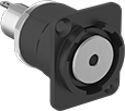 | 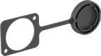 |
Stereo Connector | Plastic Cap |
These connectors mount to panels of any thickness, as long as you drill a mounting hole first.
Off (Normally Open) Circuit Position—Connectors with an off (normally open) circuit position turn equipment on when a device is plugged in.
On (Normally Closed) Circuit Position—Connectors with an on (normally closed) circuit position turn equipment off when a device is plugged in.
Caps—Protect connectors when not in use by covering them with caps (sold separately). Caps are tethered, so you can open them in any direction for access from any angle.
Receptacles | Caps | |||||||||||
|---|---|---|---|---|---|---|---|---|---|---|---|---|
Mounting | ||||||||||||
Features | Audio Connection Channel | Wire Connection Method | Housing Material | For Panel Cutout Dia. | Hole Dia. | Fasteners Included | Each | Each | ||||
Off (Normally Open) Receptacles | ||||||||||||
3.5 mm Audio × Hardwire | ||||||||||||
| 3 Conductor | Stereo | Solder | Nickel-Plated Plastic | 0.945" | 0.138" | Yes | 4540N15 | 000000 | 5286N17 | 00000 | ||
| 3 Conductor | Stereo | Solder | Black Chrome-Plated Plastic | 0.945" | 0.138" | Yes | 4540N13 | 00000 | 5286N17 | 0000 | ||
On (Normally Closed) Receptacles | ||||||||||||
3.5 mm Audio × Hardwire | ||||||||||||
| 5 Conductor | Stereo | Solder | Black Chrome-Plated Plastic | 0.945" | 0.138" | Yes | 4540N12 | 00000 | 5286N17 | 0000 | ||
