


Filter by
Voltage
Speed @ Continuous Operating Torque

Starting Torque
Continuous Operating Torque
Maximum Rotation Speed
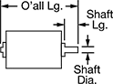
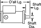
Overall Length
Power
Mounting Position
Input Voltage
Wire Connection

Power Source
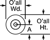
Overall Height
Overall Width
Voltage Type
Export Control Classification Number (ECCN)
DFARS Specialty Metals
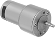
Compact DC Motors
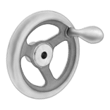
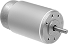
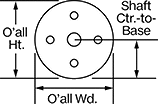
Round-Face Motors
 |
 |
 |
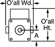
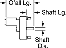
Round-face motors have a solid shaft (no keyway).
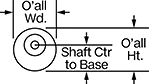
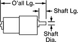
Overall | Shaft | Insulation | ||||||||||||
|---|---|---|---|---|---|---|---|---|---|---|---|---|---|---|
Speed @ Continuous Operating Torque, rpm | Full Load Current | Motor Enclosure Type | Lg. | Wd. | Ht. | Dia. | Lg. | Ctr. to Base | Class | Max. Temp., ° F | Each | |||
24V DC | ||||||||||||||
| 3,000 | 2.4 amp | Totally Enclosed Nonventilated (TENV) | 4 3/4" | 2 1/8" | 2 3/4" | 1/4" | 1" | 1.06" | F | 311 | 6331K16 | 0000000 | ||
| 3,230 | 3.2 amp | Totally Enclosed Nonventilated (TENV) | 5" | 2 1/8" | 2 3/4" | 1/4" | 1" | 1.06" | F | 311 | 6331K67 | 000000 | ||
| 4,535 | 2 amp | Totally Enclosed Nonventilated (TENV) | 4" | 1 1/2" | 1 1/2" | 0.197" | 0.562" | 0.79" | F | 311 | 6331K65 | 000000 | ||
| 5,102 | 1 amp | Totally Enclosed Nonventilated (TENV) | 2 3/4" | 1 1/2" | 1 1/2" | 0.156" | 0.562" | 0.79" | F | 311 | 6331K15 | 000000 | ||
| 5,243 | 1.3 amp | Totally Enclosed Nonventilated (TENV) | 3" | 1 1/2" | 1 1/2" | 0.156" | 0.562" | 0.79" | F | 311 | 6331K63 | 000000 | ||
| 6,172 | 0.5 amp | Totally Enclosed Nonventilated (TENV) | 2 1/2" | 1 1/4" | 1 1/4" | 0.156" | 0.562" | 0.59" | F | 311 | 6331K14 | 000000 | ||
| 8,574 | 1 amp | Totally Enclosed Nonventilated (TENV) | 3" | 1 1/4" | 1 1/4" | 0.156" | 0.562" | 0.59" | F | 311 | 6331K61 | 000000 | ||
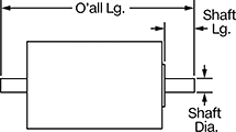
Square-Face Motors
 |
 |
 |
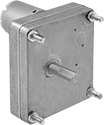
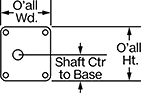
Square-face motors have a D-profile shaft.
Overall | Shaft | Insulation | ||||||||||||
|---|---|---|---|---|---|---|---|---|---|---|---|---|---|---|
Speed @ Continuous Operating Torque, rpm | Full Load Current | Motor Enclosure Type | Lg. | Wd. | Ht. | Dia. | Lg. | Ctr. to Base | Class | Max. Temp., ° F | Each | |||
24V DC | ||||||||||||||
| 3,900 | 14 amp | Totally Enclosed Nonventilated (TENV) | 9 1/2" | 4 1/4" | 5" | 1/2" | 1.44" | 1.57" | F | 311 | 59835K64 | 0000000 | ||
| 4,200 | 7.7 amp | Totally Enclosed Nonventilated (TENV) | 6 1/2" | 3 1/2" | 5" | 1/2" | 1.43" | 1.57" | F | 311 | 59835K62 | 000000 | ||
Compact DC Gearmotors
Square Face
 |
 |
 |
Overall | Shaft | Insulation | |||||||||||||
|---|---|---|---|---|---|---|---|---|---|---|---|---|---|---|---|
Speed @ Continuous Operating Torque | Power, hp | Full Load Current, amp | Lg. | Wd. | Ht. | Bearing Type | Dia. | Lg. | Ctr.-to-Base Lg. | Class | Max. Temp., ° F | Each | |||
24V DC | |||||||||||||||
| 1.2 rpm @ 800 in·ozf | 0.001 | 0.1 | 3 1/4" | 2 3/4" | 3" | Plain | 5/16" | 1" | 1.43" | B | 266 | 6409K21 | 000000 | ||
| 4 rpm @ 800 in·ozf | 0.0033 | 0.4 | 3 1/4" | 2 3/4" | 3" | Plain | 5/16" | 1" | 1.43" | B | 266 | 6409K22 | 00000 | ||
| 8 rpm @ 544 in·ozf | 0.0043 | 0.5 | 3 1/2" | 2 3/4" | 3" | Plain | 5/16" | 1" | 1.43" | B | 266 | 6409K23 | 00000 | ||
| 12 rpm @ 384 in·ozf | 0.0045 | 0.4 | 3 1/2" | 2 3/4" | 3" | Plain | 5/16" | 1" | 1.43" | B | 266 | 6409K24 | 00000 | ||
| 17 rpm @ 272 in·ozf | 0.0045 | 0.5 | 3 1/2" | 2 3/4" | 3" | Plain | 5/16" | 1" | 1.43" | B | 266 | 6409K25 | 00000 | ||
| 22 rpm @ 800 in·ozf | 0.02 | 1.1 | 4" | 2 3/4" | 3" | Plain | 5/16" | 1" | 1.43" | B | 266 | 6409K26 | 00000 | ||
| 42 rpm @ 448 in·ozf | 0.02 | 1.1 | 4" | 2 3/4" | 3" | Plain | 5/16" | 1" | 2.08" | B | 266 | 6409K27 | 00000 | ||
| 62 rpm @ 240 in·ozf | 0.02 | 0.9 | 4" | 2 3/4" | 3" | Plain | 5/16" | 1" | 1.38" | B | 266 | 6409K101 | 00000 | ||
| 70 rpm @ 160 in·ozf | 0.01 | 0.7 | 3 3/4" | 2 3/4" | 3" | Plain | 5/16" | 1" | 1.38" | B | 266 | 6409K102 | 00000 | ||
| 80 rpm @ 160 in·ozf | 0.01 | 0.9 | 3 1/2" | 2 3/4" | 3" | Plain | 5/16" | 1" | 1.38" | B | 266 | 6409K103 | 00000 | ||
| 89 rpm @ 80 in·ozf | 0.01 | 0.3 | 3 1/2" | 2 3/4" | 3" | Plain | 5/16" | 1" | 1.38" | B | 266 | 6409K104 | 00000 | ||
| 100 rpm @ 80 in·ozf | 0.01 | 0.5 | 3 1/2" | 2 3/4" | 3" | Plain | 5/16" | 1" | 1.38" | B | 266 | 6409K105 | 00000 | ||
Round Face
 |  |  |
Overall | Shaft | Insulation | |||||||||||||
|---|---|---|---|---|---|---|---|---|---|---|---|---|---|---|---|
Speed @ Continuous Operating Torque | Power, hp | Full Load Current, amp | Lg. | Wd. | Ht. | Bearing Type | Dia. | Lg. | Ctr.-to-Base Lg. | Class | Max. Temp., ° F | Each | |||
24V DC | |||||||||||||||
| 161 rpm @ 374 in·ozf | 0.0714 | 3.2 | 6 1/4" | 2 1/8" | 2 3/4" | Ball | 1/4" | 3/4" | 1" | F | 311 | 2709K18 | 0000000 | ||
| 536 rpm @ 124 in·ozf | 0.0769 | 3.2 | 6 1/4" | 2 1/8" | 2 3/4" | Ball | 1/4" | 3/4" | 1" | F | 311 | 2709K16 | 000000 | ||
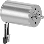
Brushless DC Motors
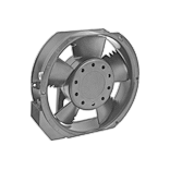
Round Face
 |
 |
 |
Round-face motors come with a connector that was used to test the motors during the manufacturing process. Before you can wire these motors to the terminals on their required driver, you will need to cut off the connector.
Overall | Shaft | Insulation | ||||||||||||||
|---|---|---|---|---|---|---|---|---|---|---|---|---|---|---|---|---|
Speed @ Continuous Operating Torque, rpm | Max. Rotation Speed, rpm | Starting Torque, in·ozf | Full Load Current | Lg. | Wd. | Ht. | Type | Dia. | Lg. | Ctr. to Base | Class | Max. Temp., ° F | Each | |||
24V DC | ||||||||||||||||
| 2,970 | 3,340 | 1,954.244 | 9.36 amp | 5 3/4" | 2" | 2" | Solid | 5/16" | 3/4" | 1.024" | F | 311 | 4853N17 | 000000000 | ||
| 4,220 | 4,720 | 784.53 | 8.96 amp | 4 1/2" | 2" | 2" | Solid | 5/16" | 3/4" | 1.02" | F | 311 | 4853N16 | 000000 | ||
| 6,870 | 7,950 | 254.901 | 3.64 amp | 3 7/8" | 1 1/8" | 1 1/8" | Solid | 1/8" | 3/4" | 0.591" | F | 311 | 4853N14 | 000000 | ||
| 7,770 | 9,190 | 50.98 | 1.52 amp | 3" | 1 1/8" | 1 1/8" | Solid | 1/8" | 3/4" | 0.591" | A | 221 | 4853N12 | 000000 | ||
| 8,840 | 9,960 | 108.758 | 2.48 amp | 3 7/8" | 1 1/8" | 1 1/8" | Solid | 1/8" | 3/4" | 0.591" | A | 221 | 4853N11 | 000000 | ||
 |
Screw-Terminal Wire Connection |
Drivers control the speed and direction the motor spins. To program the driver, connect it to your computer with a mini USB cord and use the free downloadable software to enter your speed and acceleration parameters. No coding is necessary.
Use Driver 4853N29 with Square-Face Motors with a full load current of 1.4-4.9 amps.
Use Driver 4853N19 with Round-Face Motors with a full load current of 1.52-3.64 amps.
Use Driver 4853N21 with Round-Face Motors with a full load current of 8.96-9.87 amps.
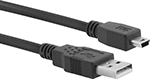 |
Connections | USB Std. | Color | Lg., ft. | Each | ||
|---|---|---|---|---|---|---|
| USB-A Male Plug × Mini USB-B Male Plug | 2.0 | Black | 6 | 4974T32 | 00000 |
DC Servomotors
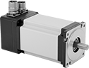 |
Often used for small automation applications, such as pick-and-place machines, these servomotors deliver lots of power in a small package. With accurate positioning and fine motor control, they create rotary motion based on signals from a drive (sold separately). The commands for speed and positioning are the same as those used for stepper motors, so you can upgrade your system without the hassle of reprogramming it. As these servomotors move, their encoder relays the shaft’s distance, direction, and speed back to the drive. The drive increases your system’s efficiency by taking the electrical signal from the encoder and dynamically adapting the motor’s movements, also accounting for inconsistent loads and unexpected forces.
Maximum Torque—Torque generally decreases as speed increases. Use a torque-speed curve to confirm which motor will work for your application. Click on a part number and select "Product Detail" to view the curve for a motor.
Servomotors | Servomotor Encoder Cords | Servomotor Power Cords | |||||||||||||||||
|---|---|---|---|---|---|---|---|---|---|---|---|---|---|---|---|---|---|---|---|
Shaft, mm | |||||||||||||||||||
Motor Frame Size | Max. Torque, in·lbf | Continuous Torque, in·lbf | Max. Rotation Speed, rpm | Current, amp | Max. Current, amp | Wattage, W | Voltage, V DC | Dia. | Lg. | No. of Counts per Rev. | Enclosure Rating | Each | Each | Each | |||||
Without Brake | |||||||||||||||||||
| 40 mm | 8.5 | 2.8 | 2,900 | 5.2 | 15.6 | 100 | 24 | 8 | 22.5 | 10,000 | IP65 | 5082N28 | 0000000 | 5082N102 | 0000000 | 5082N101 | 0000000 | ||
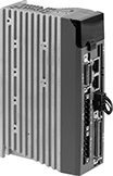 |
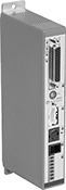
Drives have several control modes that power the motor—step and direction, position, speed, or torque. Use a computer to set motion parameters and calibrate the servomotor to your system. After initial setup, you can use a separate controller, such as a programmable logic controller (PLC), microcontroller, or indexer. A brake resistor protects the drive from regenerated electricity as the motor slows or stops.
Overall, mm | No. of Inputs/Outputs | |||||||||||||
|---|---|---|---|---|---|---|---|---|---|---|---|---|---|---|
For Motor Frame Size | Control Communication Protocol | For Max. Motor Torque | Current, amp | Operating Voltage, V DC | Lg. | Wd. | Ht. | Digital Inputs | Analog Inputs | Outputs | Each | |||
For 24V, 48V, and 60V DC Motor Voltage | ||||||||||||||
| 40 mm, 60 mm, 80 mm | — | 8.5 in·lbf to 61.1 in·lbf | 12 | 24 to 60 | 97 | 41 | 150 | 12 | 2 | 6 | 5082N35 | 0000000 | ||
| 40 mm, 60 mm, 80 mm | Modbus RTU | 8.5 in·lbf to 61.1 in·lbf | 12 | 24 to 60 | 97 | 41 | 150 | 12 | 2 | 6 | 5082N37 | 000000 | ||
| 40 mm, 60 mm, 80 mm | Modbus TCP/IP | 8.5 in·lbf to 61.1 in·lbf | 12 | 24 to 60 | 97 | 41 | 150 | 12 | 2 | 6 | 5082N36 | 000000 | ||
| 40 mm, 60 mm, 80 mm | EtherNet/IP | 8.5 in·lbf to 61.1 in·lbf | 12 | 24 to 60 | 97 | 41 | 150 | 12 | 2 | 6 | 5082N34 | 000000 | ||
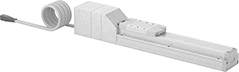
Electric Actuators with Automated Controls
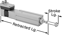 |
Automate precise push and pull movements in clamping, sorting, and ejecting tasks. These actuators come ready to use with a stepper motor and driver built in. Compared to air-powered systems, they have fewer parts to repair and replace.
These actuators have integrated controls for quick and easy setup, or you can program start and end positions remotely using digital IO or IO-Link. With IO-Link, you can move loads to a specific point along the stroke length, instead of just fully extending and retracting the rod. You can also back up your settings, configure parameters, and update firmware.
Power these actuators with a T-coded, 4-pole M12 connector. To send signals, use an A-coded, 8-pole M12 connector.
For the Manufacturer User Manual, click on a part number and select Product Detail.
-0.02 mm to 0.02 mm Repeatability—At ±0.02 mm, their repeatability is thinner than a strand of hair, so the rod hits the same spot every time.
Lg. | Extension Rod | ||||||||||||
|---|---|---|---|---|---|---|---|---|---|---|---|---|---|
Stroke, mm | Retracted | Voltage, V DC | Full Load Current, amp | Max. Speed, in/sec | Overload Protection Type | Repeatability, mm | Type | Dia. | Thread Size | Each | |||
15 lb. Dynamic Pull/Push Load Capacity | |||||||||||||
| 50 | 10 1/8" | 24 | 3 | 8.267 | Manual | -0.02 to 0.02 | Nonrotating | 0.4" | M8 × 1.25 mm | 6428N11 | 000000000 | ||
| 100 | 12" | 24 | 3 | 8.267 | Manual | -0.02 to 0.02 | Nonrotating | 0.4" | M8 × 1.25 mm | 6428N12 | 00000000 | ||
| 200 | 16" | 24 | 3 | 8.267 | Manual | -0.02 to 0.02 | Nonrotating | 0.4" | M8 × 1.25 mm | 6428N13 | 00000000 | ||
50 lb. Dynamic Pull/Push Load Capacity | |||||||||||||
| 50 | 10 7/8" | 24 | 3 | 2.913 | Manual | -0.02 to 0.02 | Nonrotating | 0.48" | M10 × 1.25 mm | 6428N14 | 00000000 | ||
| 100 | 12 7/8" | 24 | 3 | 2.913 | Manual | -0.02 to 0.02 | Nonrotating | 0.48" | M10 × 1.25 mm | 6428N15 | 00000000 | ||
| 150 | 14 7/8" | 24 | 3 | 2.913 | Manual | -0.02 to 0.02 | Nonrotating | 0.48" | M10 × 1.25 mm | 6428N16 | 00000000 | ||
| 200 | 16 3/4" | 24 | 3 | 2.913 | Manual | -0.02 to 0.02 | Nonrotating | 0.48" | M10 × 1.25 mm | 6428N17 | 00000000 | ||
| 300 | 20 3/4" | 24 | 3 | 2.913 | Manual | -0.02 to 0.02 | Nonrotating | 0.48" | M10 × 1.25 mm | 6428N18 | 00000000 | ||
100 lb. Dynamic Pull/Push Load Capacity | |||||||||||||
| 50 | 12 1/8" | 24 | 5.3 | 3.543 | Manual | -0.02 to 0.02 | Nonrotating | 0.63" | M12 × 1.25 mm | 6428N19 | 00000000 | ||
| 100 | 14 1/8" | 24 | 5.3 | 3.543 | Manual | -0.02 to 0.02 | Nonrotating | 0.63" | M12 × 1.25 mm | 6428N21 | 00000000 | ||
| 150 | 16" | 24 | 5.3 | 3.543 | Manual | -0.02 to 0.02 | Nonrotating | 0.63" | M12 × 1.25 mm | 6428N22 | 00000000 | ||
| 200 | 18" | 24 | 5.3 | 3.543 | Manual | -0.02 to 0.02 | Nonrotating | 0.63" | M12 × 1.25 mm | 6428N23 | 00000000 | ||
| 300 | 22" | 24 | 5.3 | 3.543 | Manual | -0.02 to 0.02 | Nonrotating | 0.63" | M12 × 1.25 mm | 6428N24 | 00000000 | ||
| 400 | 25 7/8" | 24 | 5.3 | 3.543 | Manual | -0.02 to 0.02 | Nonrotating | 0.63" | M12 × 1.25 mm | 6428N25 | 00000000 | ||
| 500 | 29 7/8" | 24 | 5.3 | 3.543 | Manual | -0.02 to 0.02 | Nonrotating | 0.63" | M12 × 1.25 mm | 6428N26 | 00000000 | ||
 | |
Support-Brackets Actuator Connection | Flange-Bracket Actuator Connection |
 |  |
Mounting-Bracket Actuator Connection | Trunnion-Bracket Actuator Connection |
 | |
Pivot-Bracket Actuator Connection |
For Rod Dia. | Material | Mounting Hardware Included | Each | |||
|---|---|---|---|---|---|---|
Support-Brackets Actuator Connection | ||||||
| 0.4" | Anodized Aluminum | — | 6428N27 | 000000 | ||
| 0.48", 0.63" | Anodized Aluminum | — | 6428N28 | 00000 | ||
Flange-Bracket Actuator Connection | ||||||
| 0.4" | Galvanized Steel | Yes | 6428N29 | 00000 | ||
| 0.48" | Galvanized Steel | Yes | 6428N31 | 00000 | ||
| 0.63" | Galvanized Steel | Yes | 6428N32 | 00000 | ||
Mounting-Bracket Actuator Connection | ||||||
| 0.4" | Galvanized Steel | Yes | 6428N33 | 00000 | ||
| 0.48" | Galvanized Steel | Yes | 6428N34 | 00000 | ||
| 0.63" | Galvanized Steel | Yes | 6428N35 | 00000 | ||
Trunnion-Bracket Actuator Connection | ||||||
| 0.4" | Anodized Aluminum | — | 6428N37 | 00000 | ||
| 0.48" | Anodized Aluminum | — | 6428N39 | 00000 | ||
| 0.63" | Anodized Aluminum | — | 6428N42 | 00000 | ||
Pivot-Bracket Actuator Connection | ||||||
| 0.4" | Galvanized Steel | Yes | 6428N36 | 00000 | ||
| 0.48" | Galvanized Steel | Yes | 6428N38 | 00000 | ||
| 0.63" | Galvanized Steel | Yes | 6428N41 | 00000 | ||
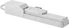
Electric Slides with Automated Controls
 |
Controller (Included) |
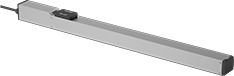 |
Slide |
With an included controller and an integrated stepper motor, these slides are a complete precision motion control system. The stepper motor moves the low-friction ball screw and carriage smoothly at high speeds, similar to an inkjet printer head. To make sure the carriage is in the right place, the built-in encoder sends data to the controller. At -0.02 to 0.02 mm, these slides have a repeatability thinner than a single strand of hair, so the carriage hits the same spot every time. They work well in automated assemblies and other processes requiring accurate, repeatable motion.
For the initial setup, program the slides using the free, downloadable software, THK D-STEP. No coding necessary—simply enter the target position, speed, and acceleration for up to 16 different slides. This software also records position, speed, and motor current data, so you can monitor performance, optimize motion, and troubleshoot issues.
After the initial setup, the controller stores and runs sequences of up to 512 unique steps on its own. The controller also communicates with other devices such as PLCs, switches, and sensors. This means it can be integrated into a larger automated system to react to or trigger other processes as the carriage moves.
For the Manufacturer User Manual, click on a part number and select Product Detail.
Dynamic load capacity is the maximum load slides can move. If you increase the speed, the dynamic load capacity decreases. Use a load-speed chart to confirm which slides will work for your application. Click on a part number and select Product Detail to view the chart.
Travel Distance per Turn—Travel distance per turn, also known as screw lead, is how far the carriage moves with one rotation of the ball screw.
Dynamic Load Cap., lb. | Overall, mm | Carriage | ||||||||||||||||
|---|---|---|---|---|---|---|---|---|---|---|---|---|---|---|---|---|---|---|
Horiz. | Vert. | Max. Speed, mm/s | Travel Distance per Turn, mm | Repeatability, mm | Lg. | Wd. | Ht. | Lg., mm | Wd., mm | Bearing Type | Base Material | Full Load Current, amp | Voltage, V DC | Operating System Compatibility | Each | |||
100 mm Stroke Length | ||||||||||||||||||
| 2 | 1 | 300 | 6 | -0.02 to 0.02 | 346 | 32 | 39 | 66.4 | 28 | Ball | Aluminum | 1.5 | 24 | Windows XP or Later | 4106N11 | 000000000 | ||
| 13 | 4 | 500 | 12 | -0.02 to 0.02 | 356 | 50 | 55 | 71 | 44 | Ball | Aluminum | 1.5 | 24 | Windows XP or Later | 4106N28 | 00000000 | ||
| 22 | 11 | 300 | 6 | -0.02 to 0.02 | 356 | 50 | 55 | 71 | 44 | Ball | Aluminum | 1.5 | 24 | Windows XP or Later | 4106N23 | 00000000 | ||
200 mm Stroke Length | ||||||||||||||||||
| 2 | 1 | 300 | 6 | -0.02 to 0.02 | 446 | 32 | 39 | 66.4 | 28 | Ball | Aluminum | 1.5 | 24 | Windows XP or Later | 4106N12 | 00000000 | ||
| 13 | 4 | 500 | 12 | -0.02 to 0.02 | 456 | 50 | 55 | 71 | 44 | Ball | Aluminum | 1.5 | 24 | Windows XP or Later | 4106N29 | 00000000 | ||
| 22 | 11 | 300 | 6 | -0.02 to 0.02 | 456 | 50 | 55 | 71 | 44 | Ball | Aluminum | 1.5 | 24 | Windows XP or Later | 4106N24 | 00000000 | ||
300 mm Stroke Length | ||||||||||||||||||
| 2 | 1 | 300 | 6 | -0.02 to 0.02 | 546 | 32 | 39 | 66.4 | 28 | Ball | Aluminum | 1.5 | 24 | Windows XP or Later | 4106N13 | 00000000 | ||
| 13 | 4 | 500 | 12 | -0.02 to 0.02 | 556 | 50 | 55 | 71 | 44 | Ball | Aluminum | 1.5 | 24 | Windows XP or Later | 4106N31 | 00000000 | ||
| 22 | 11 | 300 | 6 | -0.02 to 0.02 | 556 | 50 | 55 | 71 | 44 | Ball | Aluminum | 1.5 | 24 | Windows XP or Later | 4106N25 | 00000000 | ||
400 mm Stroke Length | ||||||||||||||||||
| 13 | 4 | 500 | 12 | -0.02 to 0.02 | 656 | 50 | 55 | 71 | 44 | Ball | Aluminum | 1.5 | 24 | Windows XP or Later | 4106N32 | 00000000 | ||
| 22 | 11 | 300 | 6 | -0.02 to 0.02 | 656 | 50 | 55 | 71 | 44 | Ball | Aluminum | 1.5 | 24 | Windows XP or Later | 4106N26 | 00000000 | ||
500 mm Stroke Length | ||||||||||||||||||
| 13 | 4 | 500 | 12 | -0.02 to 0.02 | 756 | 50 | 55 | 71 | 44 | Ball | Aluminum | 1.5 | 24 | Windows XP or Later | 4106N33 | 00000000 | ||
| 22 | 11 | 300 | 6 | -0.02 to 0.02 | 756 | 50 | 55 | 71 | 44 | Ball | Aluminum | 1.5 | 24 | Windows XP or Later | 4106N27 | 00000000 | ||
600 mm Stroke Length | ||||||||||||||||||
| 13 | 4 | 460 | 12 | -0.02 to 0.02 | 862 | 60 | 60.5 | 75 | 53 | Ball | Aluminum | 1.5 | 24 | Windows XP or Later | 4106N35 | 00000000 | ||
| 22 | 11 | 230 | 6 | -0.02 to 0.02 | 862 | 60 | 60.5 | 75 | 53 | Ball | Aluminum | 1.5 | 24 | Windows XP or Later | 4106N34 | 00000000 | ||
Rotary Electric Actuators with Automated Controls
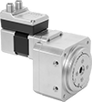 |
With a stepper motor and driver built in, these actuators come ready to use for clamping, sorting, and ejecting tasks. Their stepper motor is a bipolar hybrid, so it's precise enough to position your actuator in the right spot and efficient enough that you won't lose torque. They have integrated controls for quick and easy setup, or you can program start and end positions and track usage remotely using digital IO. Compared to air-powered systems, these actuators have fewer parts to repair and replace.
For the Manufacturer User Manual, click on a part number and select Product Detail.
0° to 90° Shaft Rotation—Actuators with a shaft rotation of 0° to 90° accelerate up to their prescribed speed at a faster rate than actuators with a shaft rotation of 0° to 180°.
Overall | ||||||||||||
|---|---|---|---|---|---|---|---|---|---|---|---|---|
Max. Torque, in·lbf | Voltage, V DC | Full Load Current, amp | Static Load Cap., lb. | Max. Rotation Speed, rpm | Repeatability | Lg. | Wd. | Ht. | Each | |||
0° to 90° Shaft Rotation | ||||||||||||
| 23.8 | 24 | 3 | 700 | 150 | -0.05° to 0.05° | 5 1/2" | 3 1/4" | 5" | 6328N11 | 000000000 | ||
| 49.5 | 24 | 5.3 | 800 | 100 | -0.1° to 0.1° | 5 1/2" | 4 1/16" | 5 7/8" | 6328N13 | 00000000 | ||
0° to 180° Shaft Rotation | ||||||||||||
| 23.8 | 24 | 3 | 700 | 150 | -0.05° to 0.05° | 5 1/2" | 3 1/4" | 5" | 6328N12 | 00000000 | ||
| 49.5 | 24 | 5.3 | 800 | 100 | -0.1° to 0.1° | 5 1/2" | 4 1/16" | 5 7/8" | 6328N14 | 00000000 | ||
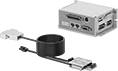
Low-Profile Electric Slides with Automated Controls
 |
Overall, mm | Carriage | ||||||||||||||||
|---|---|---|---|---|---|---|---|---|---|---|---|---|---|---|---|---|---|
Dynamic Horiz. Load Cap., lb. | Max. Speed, mm/s | Travel Distance per Full Step, mm | Repeatability, μm | Lg. | Wd. | Ht. | Lg., mm | Wd., mm | Bearing Type | Base Material | Full Load Current, amp | Voltage, V DC | Operating System Compatibility | Each | |||
10 mm Stroke Length | |||||||||||||||||
| 1 | 500 | 0.0005 | -0.5 to 0.5 | 62 | 38 | 11 | 38 | 26 | Ball | Nickel-Plated Steel | 3 | 24 | Windows 10 or Later | 6468N11 | 000000000 | ||
18 mm Stroke Length | |||||||||||||||||
| 1 | 500 | 0.0005 | -0.5 to 0.5 | 86 | 38 | 11 | 54 | 26 | Ball | Nickel-Plated Steel | 3 | 24 | Windows 10 or Later | 6468N12 | 00000000 | ||
Clean Room Electric Slides
 |
Slide |
 |
Controller (Included) |
Prevent dust from circulating while precisely positioning parts for drilling, fastening, assembly, and measuring. These slides have a built-in vacuum port to remove fine particles that could damage electronics or contaminate batches in clean rooms. Because they have an integrated stepper motor with an included controller, you can adjust the speed, timing, and positioning. At -0.02 to 0.02 mm, these slides have a repeatability thinner than a single sheet of paper, so the carriage hits the same spot every time. Unlike air-powered actuators, they’ll hold their position even if power fails. They’re also more energy efficient.
For the Manufacturer User Manual, click on a part number and select Product Detail.
Dynamic load capacity is the maximum load slides can move. If you increase the speed, the dynamic load capacity decreases. Use a load-speed chart to confirm which slides will work for your application. Click on a part number and select Product Detail to view the chart.
Maximum Speed—Maximum speed is how fast the slide will move under no-load conditions. If you increase the load, the slide speed will decrease.
Travel Distance per Full Step—Travel distance per full step determines the control you have over the slide’s positioning. The smaller the measurement, the finer positioning control you have.
Travel Distance per Turn—Travel distance per turn, also known as screw lead, is how far the carriage moves with one rotation of the ball screw.
Cords—Use a USB cord (sold separately) and free downloadable software to program the controller.
Slides | Cords | ||||||||||||||||||||
|---|---|---|---|---|---|---|---|---|---|---|---|---|---|---|---|---|---|---|---|---|---|
Dynamic Load Cap., lb. | Travel Distance per, mm | Overall, mm | Carriage | ||||||||||||||||||
Horiz. | Vert. | Max. Speed, mm/s | Full Step | Turn | Repeatability | Lg. | Wd. | Ht. | Lg., mm | Wd., mm | Bearing Type | Base Material | Full Load Current, amp | Voltage, V DC | Clean Room Std. | Each | Each | ||||
200 mm Stroke Length | |||||||||||||||||||||
| 110 | 44 | 250 | 0.08 | 8 | -0.02 mm to 0.02 mm | 541 | 70 | 84 | 122 | 60 | Ball | Aluminum | 5 | 24 | Fed. Std. Class 10, ISO Class 4 | 6833N32 | 000000000 | 6449N17 | 0000000 | ||
| 143 | 50 | 250 | 0.1 | 10 | -0.02 mm to 0.02 mm | 614.5 | 90 | 85.5 | 170 | 74 | Ball | Aluminum | 5 | 24 | Fed. Std. Class 10, ISO Class 4 | 6833N42 | 00000000 | 6449N17 | 000000 | ||
300 mm Stroke Length | |||||||||||||||||||||
| 110 | 44 | 250 | 0.08 | 8 | -0.02 mm to 0.02 mm | 641 | 70 | 84 | 122 | 60 | Ball | Aluminum | 5 | 24 | Fed. Std. Class 10, ISO Class 4 | 6833N33 | 00000000 | 6449N17 | 000000 | ||
400 mm Stroke Length | |||||||||||||||||||||
| 110 | 44 | 250 | 0.08 | 8 | -0.02 mm to 0.02 mm | 741 | 70 | 84 | 122 | 60 | Ball | Aluminum | 5 | 24 | Fed. Std. Class 10, ISO Class 4 | 6833N34 | 00000000 | 6449N17 | 000000 | ||
| 143 | 50 | 250 | 0.1 | 10 | -0.02 mm/0.02 mm | 814.5 | 90 | 85.5 | 170 | 74 | Ball | Aluminum | 5 | 24 | Fed. Std. Class 10, ISO Class 4 | 6833N44 | 00000000 | 6449N17 | 000000 | ||
600 mm Stroke Length | |||||||||||||||||||||
| 143 | 50 | 250 | 0.1 | 10 | -0.02 mm to 0.02 mm | 1,014.5 | 90 | 85.5 | 170 | 74 | Ball | Aluminum | 5 | 24 | Fed. Std. Class 10, ISO Class 4 | 6833N46 | 00000000 | 6449N17 | 000000 | ||
800 mm Stroke Length | |||||||||||||||||||||
| 143 | 50 | 250 | 0.1 | 10 | -0.02 mm to 0.02 mm | 1,214.5 | 90 | 85.5 | 170 | 74 | Ball | Aluminum | 5 | 24 | Fed. Std. Class 10, ISO Class 4 | 6833N48 | 00000000 | 6449N17 | 000000 | ||
Low-Temperature Electric Slides
 |
Slide |
 |
Controller (Included) |
Precisely position parts in conditions as cold as -90° F. These slides contain a grease that lubricates even in low temperatures. With an integrated stepper motor, they’re a complete motion control system for automated assemblies. A controller is included, so you can adjust the speed, timing, and positioning. These slides are often used in actions that require fine, repeatable movement, such as drilling, fastening, assembly, and measuring. The carriage extends the same distance every time within -0.02 to 0.02 mm, a margin thinner than a sheet of paper.
For the Manufacturer User Manual, click on a part number and select Product Detail.
Dynamic load capacity is the maximum load slides can move. If you increase the speed, the dynamic load capacity decreases. Use a load-speed chart to confirm which slides will work for your application. Click on a part number and select Product Detail to view the chart.
436 mm Overall Length—436 mm lg. slides come pre-programmed with no extra software required.
Travel Distance per Full Step—Travel distance per full step determines the control you have over the slide’s positioning. The smaller the measurement, the finer positioning control you have.
Travel Distance per Turn—Travel distance per turn, also known as screw lead, is how far the carriage moves with one rotation of the ball screw.
Cords—Use a USB cord (sold separately) and free downloadable software to program the controller for slides that are not 436 mm long.
Slides | Cords | |||||||||||||||||||
|---|---|---|---|---|---|---|---|---|---|---|---|---|---|---|---|---|---|---|---|---|
Dynamic Load Cap., lb. | Travel Distance per, mm | Overall, mm | Carriage | |||||||||||||||||
Horiz. | Vert. | Max. Speed, mm/s | Full Step | Turn | Repeatability, mm | Lg. | Wd. | Ht. | Lg., mm | Wd., mm | Bearing Type | Base Material | Full Load Current, amp | Voltage, V DC | Each | Each | ||||
100 mm Stroke Length | ||||||||||||||||||||
| 44 | 16 | 500 | 0.06 | 12 | -0.02 to 0.02 | 336 | 60 | 57.5 | 102 | 50 | Roller | Aluminum | 2.4 | 24 | 6449N21 | 000000000 | 6449N17 | 0000000 | ||
200 mm Stroke Length | ||||||||||||||||||||
| 44 | 16 | 500 | 0.06 | 12 | -0.02 to 0.02 | 436 | 60 | 57.5 | 102 | 50 | Roller | Aluminum | 2.4 | 24 | 6449N12 | 00000000 | ——— | 0 | ||
| 88 | 22 | 250 | 0.08 | 16 | -0.02 to 0.02 | 482 | 70 | 79 | 122 | 60 | Roller | Aluminum | 5.2 | 24 | 6449N24 | 00000000 | 6449N17 | 000000 | ||
300 mm Stroke Length | ||||||||||||||||||||
| 44 | 16 | 500 | 0.06 | 12 | -0.02 to 0.02 | 536 | 60 | 57.5 | 102 | 50 | Roller | Aluminum | 2.4 | 24 | 6449N23 | 00000000 | 6449N17 | 000000 | ||
400 mm Stroke Length | ||||||||||||||||||||
| 88 | 22 | 250 | 0.08 | 16 | -0.02 to 0.02 | 682 | 70 | 79 | 122 | 60 | Roller | Aluminum | 5.2 | 24 | 6449N25 | 00000000 | 6449N17 | 000000 | ||
600 mm Stroke Length | ||||||||||||||||||||
| 88 | 22 | 250 | 0.08 | 16 | -0.02 to 0.02 | 882 | 70 | 79 | 122 | 60 | Roller | Aluminum | 5.2 | 24 | 6449N26 | 00000000 | 6449N17 | 000000 | ||
