Filter by
Input Voltage
Timer Function
Mounting Location
Overall Timing
Timing Adjustment Style


Switching Voltage
Switch Starting Position
Operating Voltage
Operation Type
Electrical Connection
Certification
Wire Connection
Relay Type
Mechanical Life Cycles
Export Control Classification Number (ECCN)
DFARS Specialty Metals
About Timer Relays
Use our timing charts to compare common timer functions. Plus, learn how applying or removing input voltage triggers relays.
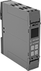
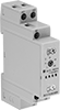
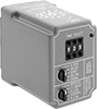
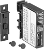
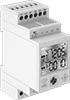
Timer Relays
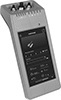
Other Products