


Filter by
System of Measurement
Material
Fitting Connection


Thread Type
Pipe Material
For Use With
Pipe Schedule

Tank Connection Method
Shape
Flanged Connection Surface
Fitting Material
OD
Specifications Met
Gender
Length
DFARS Specialty Metals
REACH

About Pipe and Fittings
Measure your pipe and fittings to identify their pipe size, thread size, schedule, and thread type. Then, find compatible components.
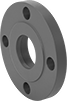
Low-Pressure Iron and Steel Threaded Pipe Flanges
Forged Flanges
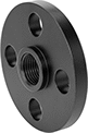 |  |
Front | Raised Surface on Back |
Pipe Size | Bolt Hole | ||||||||||||||
|---|---|---|---|---|---|---|---|---|---|---|---|---|---|---|---|
(A) | (B) | Flanged Connection Surface (B) | Flange OD | For Bolt Dia. | Dia. | No. Of | Bolt Circle Dia. | Pressure Class | Material | Max. Pressure @ Temp. | Max. Steam Pressure @ Temp. | Each | |||
NPT Female | |||||||||||||||
| 1/2 | 1/2 | Raised | 3 1/2" | 1/2" | 5/8" | 4 | 2 3/8" | 150 | A350 Carbon Steel | 285 psi @ 72° F | 230 psi @ 300° F | 5281N11 | 000000 | ||
| 3/4 | 3/4 | Raised | 3 7/8" | 1/2" | 5/8" | 4 | 2 3/4" | 150 | A350 Carbon Steel | 285 psi @ 72° F | 230 psi @ 300° F | 5281N12 | 00000 | ||
| 1 | 1 | Raised | 4 1/4" | 1/2" | 5/8" | 4 | 3 1/8" | 150 | A350 Carbon Steel | 285 psi @ 72° F | 230 psi @ 300° F | 5281N13 | 00000 | ||
| 1 1/4 | 1 1/4 | Raised | 4 5/8" | 1/2" | 5/8" | 4 | 3 1/2" | 150 | A350 Carbon Steel | 285 psi @ 72° F | 230 psi @ 300° F | 5281N14 | 00000 | ||
| 1 1/2 | 1 1/2 | Raised | 5" | 1/2" | 5/8" | 4 | 3 7/8" | 150 | A350 Carbon Steel | 285 psi @ 72° F | 230 psi @ 300° F | 5281N15 | 00000 | ||
| 2 | 2 | Raised | 6" | 5/8" | 3/4" | 4 | 4 3/4" | 150 | A350 Carbon Steel | 285 psi @ 72° F | 230 psi @ 300° F | 5281N16 | 00000 | ||
| 2 1/2 | 2 1/2 | Raised | 7" | 5/8" | 3/4" | 4 | 5 1/2" | 150 | A350 Carbon Steel | 285 psi @ 72° F | 230 psi @ 300° F | 5281N17 | 00000 | ||
| 3 | 3 | Raised | 7 1/2" | 5/8" | 3/4" | 4 | 6" | 150 | A350 Carbon Steel | 285 psi @ 72° F | 230 psi @ 300° F | 5281N18 | 00000 | ||
| 4 | 4 | Raised | 9" | 5/8" | 3/4" | 8 | 7 1/2" | 150 | A350 Carbon Steel | 285 psi @ 72° F | 230 psi @ 300° F | 5281N19 | 00000 | ||
| 6 | 6 | Raised | 11" | 3/4" | 7/8" | 8 | 9 1/2" | 150 | A350 Carbon Steel | 285 psi @ 72° F | 230 psi @ 300° F | 5281N21 | 000000 | ||
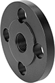
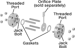
Flange Unions
Butt Weld × Flanged
 |  |
Assembled | Exploded |
Butt-weld flanges are also known as weld-neck flanges; the flange neck has a beveled end that, when flush to pipe, creates a trough for a strong weld.
ASME B16.36—Flanges that meet ASME B16.36 adhere to specifications and testing requirements for temperature and pressure ratings, dimensions, materials, and tolerances.
Bolt Hole | Port | For Carbon Steel Fittings | |||||||||||||||
|---|---|---|---|---|---|---|---|---|---|---|---|---|---|---|---|---|---|
Pipe Size | Construction | Flange OD | For Bolt Dia. | Dia. | No. of | Bolt Circle Dia. | Pipe Size | No. of | Includes | Specs. Met | For Use With | Temp. | Pressure Class | For Pipe Material | Each | ||
| 3/4 | Seamless | 4 5/8" | 5/8" | 11/16" | 4 | 3 1/4" | 1/2 | 2 | Gaskets, Jack Bolts, Nuts, Port Plugs, Threaded Rods | — | Air, Natural Gas, Oil, Water | Not Rated | 300 | Carbon Steel | 5291N11 | 0000000 | |
| 1 | Seamless | 4 7/8" | 5/8" | 11/16" | 4 | 3 1/2" | 1/2 | 2 | Gaskets, Jack Bolts, Nuts, Port Plugs, Threaded Rods | ASME B16.36 | Air, Natural Gas, Oil, Water | Not Rated | 300 | Carbon Steel | 5291N12 | 000000 | |
| 1 1/2 | Seamless | 6 1/8" | 3/4" | 13/16" | 4 | 4 1/2" | 1/2 | 2 | Gaskets, Jack Bolts, Nuts, Port Plugs, Threaded Rods | ASME B16.36 | Air, Natural Gas, Oil, Water | Not Rated | 300 | Carbon Steel | 5291N13 | 000000 | |
| 2 | Seamless | 6 1/2" | 5/8" | 11/16" | 8 | 5" | 1/2 | 2 | Gaskets, Jack Bolts, Nuts, Port Plugs, Threaded Rods | ASME B16.36 | Air, Natural Gas, Oil, Water | Not Rated | 300 | Carbon Steel | 5291N14 | 000000 | |
| 3 | Seamless | 8 1/4" | 3/4" | 13/16" | 8 | 6 9/16" | 1/2 | 2 | Gaskets, Jack Bolts, Nuts, Port Plugs, Threaded Rods | ASME B16.36 | Air, Natural Gas, Oil, Water | Not Rated | 300 | Carbon Steel | 5291N15 | 000000 | |
| 4 | Seamless | 10" | 3/4" | 13/16" | 8 | 7 7/8" | 1/2 | 2 | Gaskets, Jack Bolts, Nuts, Port Plugs, Threaded Rods | ASME B16.36 | Air, Natural Gas, Oil, Water | Not Rated | 300 | Carbon Steel | 5291N16 | 000000 | |
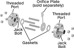
Slip-On Weld × Flanged
 |  |
Assembled | Exploded |
Bolt Hole | Port | For Carbon Steel Fittings | ||||||||||||||
|---|---|---|---|---|---|---|---|---|---|---|---|---|---|---|---|---|
Pipe Size | Flange OD | For Bolt Dia. | Dia. | No. of | Bolt Circle Dia. | Pipe Size | No. of | Includes | Specs. Met | For Use With | Temp. | Pressure Class | For Pipe Material | Each | ||
| 3/4 | 4 5/8" | 5/8" | 11/16" | 4 | 3 1/4" | 1/2 | 2 | Gaskets, Jack Bolts, Nuts, Port Plugs, Threaded Rods | — | Air, Natural Gas, Oil, Water | Not Rated | 300 | Carbon Steel | 5291N17 | 0000000 | |
| 1 | 4 7/8" | 5/8" | 11/16" | 4 | 3 1/2" | 1/2 | 2 | Gaskets, Jack Bolts, Nuts, Port Plugs, Threaded Rods | ASME B16.36 | Air, Natural Gas, Oil, Water | Not Rated | 300 | Carbon Steel | 5291N18 | 000000 | |
| 1 1/2 | 6 1/8" | 3/4" | 13/16" | 4 | 4 1/2" | 1/2 | 2 | Gaskets, Jack Bolts, Nuts, Port Plugs, Threaded Rods | ASME B16.36 | Air, Natural Gas, Oil, Water | Not Rated | 300 | Carbon Steel | 5291N19 | 000000 | |
| 2 | 6 1/2" | 5/8" | 11/16" | 8 | 5" | 1/2 | 2 | Gaskets, Jack Bolts, Nuts, Port Plugs, Threaded Rods | ASME B16.36 | Air, Natural Gas, Oil, Water | Not Rated | 300 | Carbon Steel | 5291N21 | 000000 | |
| 3 | 8 1/4" | 3/4" | 13/16" | 8 | 6 9/16" | 1/2 | 2 | Gaskets, Jack Bolts, Nuts, Port Plugs, Threaded Rods | ASME B16.36 | Air, Natural Gas, Oil, Water | Not Rated | 300 | Carbon Steel | 5291N22 | 000000 | |
| 4 | 10" | 3/4" | 13/16" | 8 | 7 7/8" | 1/2 | 2 | Gaskets, Jack Bolts, Nuts, Port Plugs, Threaded Rods | ASME B16.36 | Air, Natural Gas, Oil, Water | Not Rated | 300 | Carbon Steel | 5291N23 | 000000 | |
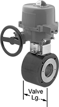
High-Flow Flanged Motor-Actuated On/Off Valves
Carbon Steel Body with Screw-Terminal Wire Connection
 |
Flow Coefficient (Cv)—Flow coefficient (Cv) is the amount of water (in gallons per minute) at 60° F that will flow through a fully open valve with a difference of 1 psi between the inlet and the outlet.
Bolts | Overall | |||||||||||||||||||||
|---|---|---|---|---|---|---|---|---|---|---|---|---|---|---|---|---|---|---|---|---|---|---|
Pipe Size | Fitting Connection | Gender | Port Type | Flange OD | No. of Holes | Hole Size | Included | Circle Dia. | Flow Coefficient (Cv) | Max. Pressure @ Temp. | Max. Steam Pressure @ Temp. | Manual Override | Valve Type | Temp. Range, ° F | Valve Lg. | Lg. | Ht. | Specs. Met | Each | |||
Fail in Place—24V AC/24V DC | ||||||||||||||||||||||
| 2 | Flanged | Female | Full | 6" | 4 | 5/8" | No | 4 3/4" | 307.4 | 275 psi @ 100° F | 100 psi @ 338° F | Yes | Ball Zero Pressure Drop | 0 to 365 | 3 1/4" | 7 3/4" | 15 1/4" | ASME B16.34 | 2531N14 | 000000000 | ||
| 3 | Flanged | Female | Full | 7 1/4" | 4 | 5/8" | No | 6" | 1,012.68 | 275 psi @ 100° F | 100 psi @ 338° F | Yes | Ball Zero Pressure Drop | 0 to 365 | 4 13/16" | 10 1/2" | 22 5/8" | ASME B16.34 | 2531N15 | 00000000 | ||
Fail in Place—120V AC | ||||||||||||||||||||||
| 2 | Flanged | Female | Full | 6" | 4 | 5/8" | No | 4 3/4" | 307.4 | 275 psi @ 100° F | 100 psi @ 338° F | Yes | Ball Zero Pressure Drop | 0 to 365 | 3 1/4" | 7 3/4" | 19 1/16" | ASME B16.34 | 2531N11 | 00000000 | ||
| 3 | Flanged | Female | Full | 7 1/4" | 4 | 5/8" | No | 6" | 1,012.68 | 275 psi @ 100° F | 100 psi @ 338° F | Yes | Ball Zero Pressure Drop | 0 to 365 | 4 13/16" | 10 1/2" | 22 5/8" | ASME B16.34 | 2531N12 | 00000000 | ||
Low-Pressure Iron and Steel Threaded Pipe Fittings
Straight Adapters for Tanks
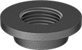 |
Female × Butt Weld (For Flat Surface) |
Pipe Size | For Hole Diameter (B) | OD | For Tank Surface (B) | Material | Max. Pressure @ Temp. | Each | |||
|---|---|---|---|---|---|---|---|---|---|
NPT Female × Butt Weld | |||||||||
| 1/4 | 3/4" | 1 1/4" | Flat | Carbon Steel | Not Rated | 12555K51 | 00000 | ||
| 3/8 | 15/16" | 1 1/4" | Flat | Carbon Steel | Not Rated | 12555K52 | 00000 | ||
| 1/2 | 1 1/8" | 1 1/2" | Flat | Carbon Steel | Not Rated | 12555K53 | 0000 | ||
| 3/4 | 1 3/8" | 1 3/4" | Flat | Carbon Steel | Not Rated | 12555K54 | 0000 | ||
| 1 | 1 11/16" | 2 1/8" | Flat | Carbon Steel | Not Rated | 12555K55 | 0000 | ||
| 1 1/4 | 2" | 2 1/2" | Flat | Carbon Steel | Not Rated | 12555K56 | 0000 | ||
| 1 1/2 | 2 3/8" | 3" | Flat | Carbon Steel | Not Rated | 12555K57 | 00000 | ||
| 2 | 2 7/8" | 3 1/2" | Flat | Carbon Steel | Not Rated | 12555K58 | 00000 | ||
| 2 1/2 | 3 1/2" | 4 1/4" | Flat | Carbon Steel | Not Rated | 12555K59 | 00000 | ||
| 3 | 4 1/8" | 4 3/4" | Flat | Carbon Steel | Not Rated | 12555K61 | 00000 | ||
| 4 | 5 1/8" | 5 3/4" | Flat | Carbon Steel | Not Rated | 12555K62 | 00000 | ||
Straight Adapters with Extension for Tanks
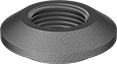 |
Female × Butt Weld |
Pipe Size | For Hole Diameter (B) | OD | For Tank Surface (B) | Material | Max. Pressure @ Temp. | Each | |||
|---|---|---|---|---|---|---|---|---|---|
NPT Female × Butt Weld | |||||||||
| 1/8 | 15/16" | 1 5/16" | Flat | Carbon Steel | Not Rated | 12555K79 | 00000 | ||
| 1/8 | 15/16" | 1 1/2" | Flat | Carbon Steel | Not Rated | 12555K69 | 0000 | ||
| 1/4 | 15/16" | 1 5/16" | Flat | Carbon Steel | Not Rated | 12555K81 | 0000 | ||
| 1/4 | 15/16" | 1 1/2" | Flat | Carbon Steel | Not Rated | 12555K71 | 0000 | ||
| 3/8 | 15/16" | 1 5/16" | Flat | Carbon Steel | Not Rated | 12555K82 | 0000 | ||
| 3/8 | 15/16" | 1 1/2" | Flat | Carbon Steel | Not Rated | 12555K72 | 0000 | ||
| 1/2 | 1 1/8" | 1 5/8" | Flat | Carbon Steel | Not Rated | 12555K83 | 0000 | ||
| 1/2 | 1 1/8" | 1 3/4" | Flat | Carbon Steel | Not Rated | 12555K73 | 0000 | ||
| 3/4 | 1 5/16" | 1 15/16" | Flat | Carbon Steel | Not Rated | 12555K84 | 0000 | ||
| 3/4 | 1 3/8" | 2 1/8" | Flat | Carbon Steel | Not Rated | 12555K74 | 0000 | ||
| 1 | 1 5/8" | 2 3/8" | Flat | Carbon Steel | Not Rated | 12555K75 | 0000 | ||
| 1 | 1 11/16" | 2 1/4" | Flat | Carbon Steel | Not Rated | 12555K85 | 0000 | ||
| 1 1/4 | 2" | 2 9/16" | Flat | Carbon Steel | Not Rated | 12555K86 | 00000 | ||
| 1 1/4 | 2" | 2 11/16" | Flat | Carbon Steel | Not Rated | 12555K76 | 0000 | ||
| 1 1/2 | 2 1/4" | 2 13/16" | Flat | Carbon Steel | Not Rated | 12555K87 | 0000 | ||
| 1 1/2 | 2 1/4" | 3" | Flat | Carbon Steel | Not Rated | 12555K77 | 0000 | ||
| 2 | 2 5/8" | 3 3/8" | Flat | Carbon Steel | Not Rated | 12555K88 | 0000 | ||
| 2 | 2 5/8" | 3 1/2" | Flat | Carbon Steel | Not Rated | 12555K78 | 00000 | ||
| 2 1/2 | 3 1/8" | 4 1/16" | Flat | Carbon Steel | Not Rated | 12555K89 | 00000 | ||
| 3 | 3 5/8" | 4 5/8" | Flat | Carbon Steel | Not Rated | 12555K91 | 00000 | ||
| 4 | 4 11/16" | 5 13/16" | Flat | Carbon Steel | Not Rated | 12555K92 | 00000 | ||
180° Bend Connectors
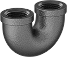 |
180° bend connectors are also known as U-bends.
Pipe Size | Material | Max. Pressure @ Temp. | Max. Steam Pressure @ Temp. | Certification | Shape | Each | |||
|---|---|---|---|---|---|---|---|---|---|
NPT Female | |||||||||
| 1/2 | Iron | 150 psi @ 72° F | 150 psi @ 350° F | UL Listed | 180° Bend | 44605K563 | 000000 | ||
| 3/4 | Iron | 150 psi @ 72° F | 150 psi @ 350° F | UL Listed | 180° Bend | 44605K564 | 00000 | ||
| 1 | Iron | 150 psi @ 72° F | 150 psi @ 350° F | — | 180° Bend | 44605K565 | 00000 | ||
| 1 1/4 | Iron | 150 psi @ 72° F | 150 psi @ 350° F | UL Listed | 180° Bend | 44605K566 | 00000 | ||
| 1 1/2 | Iron | 150 psi @ 72° F | 150 psi @ 350° F | UL Listed | 180° Bend | 44605K567 | 000000 | ||
| 2 | Iron | 150 psi @ 72° F | 150 psi @ 350° F | UL Listed | 180° Bend | 44605K568 | 000000 | ||
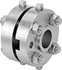
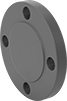
Low-Pressure Iron and Steel Unthreaded Pipe Flanges
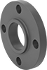
Forged Flanges
 |  |  |  | 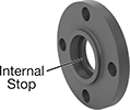 |  |
Butt Weld: Front | Butt Weld: Raised Surface on Back | Slip-On Weld: Front | Slip-On Weld: Raised Surface on Back | Socket Connect: Front | Socket Connect: Raised Surface on Back |
Pipe Size | Bolt Hole | ||||||||||||||
|---|---|---|---|---|---|---|---|---|---|---|---|---|---|---|---|
(A) | (B) | Flanged Connection Surface (B) | Flange OD | For Bolt Dia. | Dia. | No. Of | Bolt Circle Dia. | Pressure Class | Material | Max. Pressure @ Temp. | Max. Steam Pressure @ Temp. | Each | |||
Butt Weld | |||||||||||||||
| 2 | 2 | Raised | 6" | 5/8" | 3/4" | 4 | 4 3/4" | 150 | A350 Carbon Steel | 285 psi @ 72° F | 230 psi @ 300° F | 5235N11 | 000000 | ||
| 3 | 3 | Raised | 7 1/2" | 5/8" | 3/4" | 4 | 6" | 150 | A350 Carbon Steel | 285 psi @ 72° F | 230 psi @ 300° F | 5235N12 | 00000 | ||
| 4 | 4 | Raised | 9" | 5/8" | 3/4" | 8 | 7 1/2" | 150 | A350 Carbon Steel | 285 psi @ 72° F | 230 psi @ 300° F | 5235N13 | 00000 | ||
| 6 | 6 | Raised | 11" | 3/4" | 7/8" | 8 | 9 1/2" | 150 | A350 Carbon Steel | 285 psi @ 72° F | 230 psi @ 300° F | 5235N14 | 000000 | ||
Slip-On Weld Female | |||||||||||||||
| 1 | 1 | Raised | 4 1/4" | 1/2" | 5/8" | 4 | 3 1/8" | 150 | A350 Carbon Steel | 285 psi @ 72° F | 230 psi @ 300° F | 5235N15 | 00000 | ||
| 1 1/2 | 1 1/2 | Raised | 5" | 1/2" | 5/8" | 4 | 3 7/8" | 150 | A350 Carbon Steel | 285 psi @ 72° F | 230 psi @ 300° F | 5235N16 | 00000 | ||
| 2 | 2 | Raised | 6" | 5/8" | 3/4" | 4 | 4 3/4" | 150 | A350 Carbon Steel | 285 psi @ 72° F | 230 psi @ 300° F | 5235N17 | 00000 | ||
| 2 1/2 | 2 1/2 | Raised | 7" | 5/8" | 3/4" | 4 | 5 1/2" | 150 | A350 Carbon Steel | 285 psi @ 72° F | 230 psi @ 300° F | 5235N18 | 00000 | ||
| 3 | 3 | Raised | 7 1/2" | 5/8" | 3/4" | 4 | 6" | 150 | A350 Carbon Steel | 285 psi @ 72° F | 230 psi @ 300° F | 5235N19 | 00000 | ||
| 4 | 4 | Raised | 9" | 5/8" | 3/4" | 8 | 7 1/2" | 150 | A350 Carbon Steel | 285 psi @ 72° F | 230 psi @ 300° F | 5235N21 | 00000 | ||
| 6 | 6 | Raised | 11" | 3/4" | 7/8" | 8 | 9 1/2" | 150 | A350 Carbon Steel | 285 psi @ 72° F | 230 psi @ 300° F | 5235N22 | 000000 | ||
| 8 | 8 | Raised | 13 1/2" | 3/4" | 7/8" | 8 | 11 3/4" | 150 | A350 Carbon Steel | 285 psi @ 72° F | 230 psi @ 300° F | 5235N23 | 000000 | ||
Socket-Connect Female | |||||||||||||||
| 2 | 2 | Raised | 6" | 5/8" | 3/4" | 4 | 4 3/4" | 150 | A350 Carbon Steel | 285 psi @ 72° F | 230 psi @ 300° F | 5235N24 | 00000 | ||
| 3 | 3 | Raised | 7 1/2" | 5/8" | 3/4" | 4 | 6" | 150 | A350 Carbon Steel | 285 psi @ 72° F | 230 psi @ 300° F | 5235N25 | 00000 | ||
| 4 | 4 | Raised | 9" | 5/8" | 3/4" | 8 | 7 1/2" | 150 | A350 Carbon Steel | 285 psi @ 72° F | 230 psi @ 300° F | 5235N26 | 00000 | ||
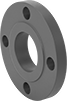
Forged Blind Flanges
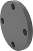 |  |
Front | Raised Surface on Back |
Bolt Hole | ||||||||||||||
|---|---|---|---|---|---|---|---|---|---|---|---|---|---|---|
Pipe Size | Flanged Connection Surface | Flange OD | For Bolt Dia. | Dia. | No. Of | Bolt Circle Dia. | Pressure Class | Material | Max. Pressure @ Temp. | Max. Steam Pressure @ Temp. | Each | |||
Flanged | ||||||||||||||
| 1 | Raised | 4 1/2" | 1/2" | 5/8" | 4 | 3 1/8" | 150 | A350 Carbon Steel | 285 psi @ 72° F | 230 psi @ 300° F | 5235N27 | 000000 | ||
| 1 1/2 | Raised | 5" | 1/2" | 5/8" | 4 | 3 7/8" | 150 | A350 Carbon Steel | 285 psi @ 72° F | 230 psi @ 300° F | 5235N28 | 00000 | ||
| 2 | Raised | 6" | 5/8" | 3/4" | 4 | 4 3/4" | 150 | A350 Carbon Steel | 285 psi @ 72° F | 230 psi @ 300° F | 5235N29 | 00000 | ||
| 2 1/2 | Raised | 7" | 5/8" | 3/4" | 4 | 5 1/2" | 150 | A350 Carbon Steel | 285 psi @ 72° F | 230 psi @ 300° F | 5235N31 | 00000 | ||
| 3 | Raised | 7 1/2" | 5/8" | 3/4" | 4 | 6" | 150 | A350 Carbon Steel | 285 psi @ 72° F | 230 psi @ 300° F | 5235N32 | 00000 | ||
| 4 | Raised | 9" | 5/8" | 3/4" | 8 | 7 1/2" | 150 | A350 Carbon Steel | 285 psi @ 72° F | 230 psi @ 300° F | 5235N33 | 00000 | ||
| 6 | Raised | 11" | 3/4" | 7/8" | 8 | 9 1/2" | 150 | A350 Carbon Steel | 285 psi @ 72° F | 230 psi @ 300° F | 5235N34 | 000000 | ||
| 8 | Raised | 13 1/2" | 3/4" | 7/8" | 8 | 11 3/4" | 150 | A350 Carbon Steel | 285 psi @ 72° F | 230 psi @ 300° F | 5235N35 | 000000 | ||
High-Flow Flanged Air-Driven On/Off Valves
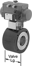 |
Their ball-valve design allows these valves to handle three times the flow of other flanged valves. They operate on compressed air to automatically start and stop flow faster actuation than motor-driven valves. You must control the air to the actuator using either the included electric pilot valve or a manual on/off valve (not included). These valves don’t require a minimum pressure drop between the inlet and outlet for operation. All are full port, so they do not restrict flow.
The actuator is secured to the valve body with a bracket for easy disassembly, maintenance, and repair. A visual flow indicator on the top of the actuator shows whether the valve is open or closed. The manual override allows you to operate the valve during power outages.
Single Acting—Single-acting actuators only require air pressure to open the valve; they automatically spring closed when the air turns off. These valves are fail closed unless actuated.
Double Acting—Double-acting actuators require air pressure to open and close the valve. Once actuated, these valves remain actuated until air pressure is applied to close them, so they do not have a valve starting position.
Flow Coefficient (Cv)—Flow coefficient (Cv) is the amount of water (in gallons per minute) at 60° F that will flow through a fully open valve with a difference of 1 psi between the inlet and the outlet.
Bolts | Air | ||||||||||||||||||||
|---|---|---|---|---|---|---|---|---|---|---|---|---|---|---|---|---|---|---|---|---|---|
Pipe Size | Gender | Flange OD | No. of Holes | Hole Size | Included | Circle Dia. | Flow Coefficient (Cv) | Max. Pressure @ Temp. | Max. Steam Pressure @ Temp. | Valve Type | Temp. Range, ° F | Valve Lg. | Overall Ht. | Connection | Min. Pressure, psi | Max. Pressure, psi | Specs. Met | Each | |||
Carbon Steel Body with Screw Terminals | |||||||||||||||||||||
Single Acting: Air-to-Open, Spring Return (Fail Closed)—120V AC | |||||||||||||||||||||
| 2 | Female | 6" | 4 | 5/8" | No | 4 3/4" | 307.4 | 285 psi @ 100° F | 100 psi @ 338° F | Ball, Zero Pressure Drop | 0 to 365 | 3 1/4" | 14" | 1/4 NPT Female | 40 | 115 | ASME B16.34 | 2534N14 | 000000000 | ||
| 3 | Female | 7 1/2" | 4 | 5/8" | No | 6" | 1,012.68 | 285 psi @ 100° F | 100 psi @ 338° F | Ball, Zero Pressure Drop | 0 to 365 | 4 13/16" | 18 5/16" | 1/4 NPT Female | 40 | 115 | ASME B16.34 | 2534N15 | 00000000 | ||
Double Acting: Air-to-Open, Air-to-Close—120V AC | |||||||||||||||||||||
| 2 | Female | 6" | 4 | 5/8" | No | 4 3/4" | 307.4 | 285 psi @ 100° F | 100 psi @ 338° F | Ball, Zero Pressure Drop | 0 to 365 | 3 1/4" | 12 15/16" | 1/4 NPT Female | 40 | 115 | ASME B16.34 | 2534N11 | 000000 | ||
| 3 | Female | 7 1/4" | 4 | 5/8" | No | 6" | 1,012.68 | 285 psi @ 100° F | 100 psi @ 338° F | Ball, Zero Pressure Drop | 0 to 365 | 4 13/16" | 19 15/16" | 1/4 NPT Female | 40 | 115 | ASME B16.34 | 2534N12 | 00000000 | ||
