



























Filter by


Actuation Type


Export Control Classification Number (ECCN)
DFARS Specialty Metals
Maximum Pressure
Holding Capacity


Air-Powered Machine Vises
With Flat Jaws
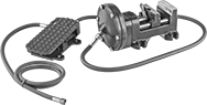 | 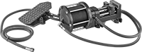 |
Fixed Base—Single Acting | Fixed Base—Double Acting |
Single Acting—Single-acting vises require the jaw to be manually set to the desired position before use, so these vises are best for repetitive clamping of consistent workpiece sizes. Once the jaw is set, activating the air pressure will move the jaw up to 5/8" to clamp. When air pressure is released, a spring return inside the air cylinder returns the jaw to the set position.
Double Acting—Double-acting vises use air pressure to open and close the jaws without manual adjustment, making these vises a good choice when clamping workpieces of varying size.
Jaw | Air Inlet | Body | Mounting Holes | |||||||||||||||||||
|---|---|---|---|---|---|---|---|---|---|---|---|---|---|---|---|---|---|---|---|---|---|---|
Wd. | Ht. | Max. Opening | Material | Texture | Replaceable | Pipe Size | Thread Type | Gender | Max. Pressure, psi | Gripping Force Factor | Overall Ht. | Lg. | Material | Mount Type | Mounting Fasteners Included | No. of | Dia. | Includes | Each | |||
Fixed Base—Single Acting | ||||||||||||||||||||||
| 3" | 1 1/4" | 3 1/8" | Steel | Smooth | Yes | 1/4 | NPSM | Male | 120 | 15 | 5 3/8" | 10 1/4" | Iron | Bolt On | No | 4 | 17/32" | Two 5-ft. Long Air Hoses | 5269A24 | 0000000 | ||
| 4" | 1 5/16" | 4 5/8" | Steel | Smooth | Yes | 1/4 | NPSM | Male | 120 | 15 | 5 3/8" | 13 1/2" | Iron | Bolt On | No | 4 | 21/32" | Two 5-ft. Long Air Hoses | 5269A21 | 000000 | ||
Fixed Base—Double Acting | ||||||||||||||||||||||
| 3" | 1 1/4" | 3 1/8" | Steel | Smooth | Yes | 1/4 | NPSM | Male | 120 | 15 | 5 3/8" | 13 11/16" | Iron | Bolt On | No | 4 | 17/32" | Three 5-ft. Long Air Hoses | 5269A25 | 000000 | ||
| 4" | 1 5/16" | 5" | Steel | Smooth | Yes | 1/4 | NPSM | Male | 120 | 15 | 5 3/8" | 18 1/4" | Iron | Bolt On | No | 4 | 21/32" | Three 5-ft. Long Air Hoses | 5269A22 | 000000 | ||
| 6" | 2 1/2" | 7 3/8" | Steel | Smooth | Yes | 1/4 | NPSM | Male | 120 | 19 | 6 17/32" | 25 5/8" | Iron | Bolt On | No | 4 | 11/16" | Three 5-ft. Long Air Hoses | 5269A23 | 00000000 | ||
Air-Powered Hold-Down Toggle Clamps
 |  |
With Open Arm | With Solid Arm |
Arm | When Clamped | Holding Screws | Air Inlet and Outlet | |||||||||||||||||
|---|---|---|---|---|---|---|---|---|---|---|---|---|---|---|---|---|---|---|---|---|
Holding Cap., lb. | Max. Clamping Clearance | Ht. | Lg. | Opening Angle | Overall Lg. | Overall Ht. | No. of | Tip Material | Thread Size | Max. Air Inlet Pressure, psi | Pipe Size | Thread Size | Thread Type | Gender | Temp. Range, ° F | Body Material | Each | |||
With Open Arm | ||||||||||||||||||||
| 100 | 3/8" | 3/4" | 1 1/8" | 95° | 5 5/8" | 1 5/8" | 2 | Steel, Rubber | M5 | 40 | — | M5 | Metric | Female | -10 to 165 | Steel | 5174A35 | 0000000 | ||
| 200 | 5/8" | 1 1/8" | 1 3/4" | 100° | 7 3/4" | 2 5/8" | 2 | Steel, Rubber | M6 | 30 | 1/8 | — | NPT | Female | -10 to 165 | Steel | 5129A21 | 000000 | ||
| 375 | 29/32" | 1 3/8" | 2 1/2" | 100° | 9 3/8" | 3" | 2 | Steel, Rubber | 5/16"-18 | 45 | 1/8 | — | NPT | Female | -10 to 165 | Steel | 5129A22 | 000000 | ||
| 600 | 1 7/32" | 1 7/8" | 3 5/8" | 95° | 11 3/4" | 3 7/8" | 2 | Steel, Rubber | 3/8"-16 | 50 | 1/8 | — | NPT | Female | -10 to 165 | Steel | 5129A23 | 000000 | ||
| 1,000 | 1 15/32" | 2 1/4" | 4 7/8" | 90° | 15 1/4" | 4 1/2" | 2 | Steel, Rubber | 1/2"-13 | 75 | 1/4 | — | NPT | Female | -10 to 165 | Steel | 5129A24 | 000000 | ||
With Solid Arm | ||||||||||||||||||||
| 4,000 | 3 7/8" | 3 7/8" | 4 13/16" | 95° | 17 1/2" | 7 1/8" | — | — | — | 145 | 1/4 | — | NPT | Female | -14 to 194 | Steel | 5129A25 | 000000 | ||
Air-Powered Push Toggle Clamps
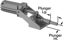 |
Use for repetitive clamping and in production environments. These clamps secure when the plunger is fully extended to hold a workpiece from the side. Air from one inlet port engages the clamp, and air from the other inlet port disengages it. Clamps maintain the full-rated holding capacity even with a loss of air pressure. They have a threaded plunger to accommodate threaded holding screws and other threaded fixtures (not included). Fittings (not included) are required to connect the clamp's ports to a control valve and an air line.
Plunger | When Clamped | Air Inlet and Outlet | |||||||||||||||||
|---|---|---|---|---|---|---|---|---|---|---|---|---|---|---|---|---|---|---|---|
Holding Cap., lb. | Lg. | Ht. | Travel | Shape | Dia. | Thread Location | Thread Size | Thread Lg. | Overall Ht. | Overall Lg. | Max. Air Inlet Pressure, psi | Pipe Size | Thread Type | Gender | Temp. Range, ° F | Each | |||
Push Only—Steel | |||||||||||||||||||
| 600 | 1 1/4" | 1 1/8" | 3/4" | Round | 7/16" | Internal | 5/16"-18 | 1" | 3" | 9 7/8" | 60 | 1/8 | NPT | Female | -10 to 165 | 5137A51 | 0000000 | ||
| 2,500 | 2" | 1 1/8" | 1 1/4" | Round | 5/8" | Internal | 3/8"-16 | 1 1/4" | 3 5/8" | 13 1/2" | 145 | 1/8 | NPT | Female | -10 to 165 | 5137A52 | 000000 | ||
| 16,000 | 3 3/8" | 2 5/8" | 2" | Round | 1" | Internal | 5/8"-11 | 2" | 7 1/4" | 20 5/8" | 145 | 1/4 | NPT | Female | -10 to 165 | 5137A53 | 000000 | ||
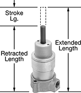
Short-Stroke Clamping Air Cylinders
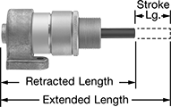
Vertical Mount
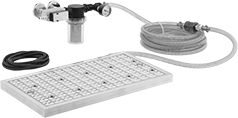
Vacuum Workholding Plates
Plates
 |
Air Inlet | Mounting Holes | |||||||||||||||
|---|---|---|---|---|---|---|---|---|---|---|---|---|---|---|---|---|
Lg. | Wd. | Ht. | Max. Vacuum, in. Hg | Recommended Operating Air Pressure, psi | Air Consumption @ Pressure | Connection Port | Quick-Disconnect Style | Coupling Size | Gender | No. of | Dia. | Ctr.-to-Ctr. | Includes | Each | ||
| 17 3/4" | 9 1/2" | 1" | 27.9 | 58 to 110 | 3.4 scfm @ 58 psi | Hose | Industrial | 1/4 | Male | 2 | 1/2" | 15 3/8" | Vacuum Generator, 15 ft. Vacuum Hose, 10 ft. EPDM Foam Gasketing | 1421N11 | 000000000 | |
| 17 3/4" | 12" | 1" | 27.9 | 58 to 110 | 3.4 scfm @ 58 psi | Hose | Industrial | 1/4 | Male | 2 | 1/2" | 15 3/8" | Vacuum Generator, 15 ft. Vacuum Hose, 15 ft. EPDM Foam Gasketing | 1421N18 | 00000000 | |
| 17 3/4" | 14" | 1" | 27.9 | 58 to 110 | 3.4 scfm @ 58 psi | Hose | Industrial | 1/4 | Male | 2 | 1/2" | 15 3/8" | Vacuum Generator, 15 ft. Vacuum Hose, 15 ft. EPDM Foam Gasketing | 1421N23 | 00000000 | |
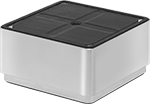
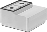
Retracting Stop Pins
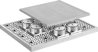 | 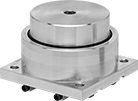 |
Retracting Stop Pins with Pin Retracted |
Base | ||||||||
|---|---|---|---|---|---|---|---|---|
Dia. | Retracted Ht. | Extended Ht. | Lg. | Wd. | Material | Each | ||
| 2 3/8" | 1.345" | 1.971" | 3" | 3" | Aluminum | 1421N14 | 0000000 | |
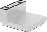
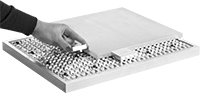
Side Stops
 |
Lg. | Wd. | Ht. | Material | Each | ||
|---|---|---|---|---|---|---|
| 2 1/8" | 1 3/4" | 1/2" | Aluminum | 1421N24 | 000000 |
Threaded Air-Powered Hold-Down Fixture Clamps for Welding
 |  |
Rubber Holding Screw Tip | Steel Holding Screw Tip |
 |  |
Extended Clamping Arm | Clamping Arm Adapter |
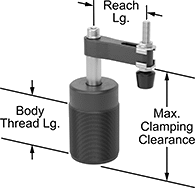
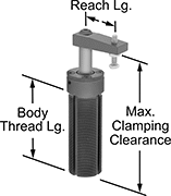
Screw these clamps directly into a tapped hole and use air pressure to quickly and consistently clamp and release parts when welding. Compact and lightweight, these clamps are easy to move and reposition when welding. They’re also known as swing clamps. Connect these clamps to a control valve and air line. When pressure is applied, the arm on these clamps rotates 90° into position over your workpiece before clamping down. When pressure is released, the arm rises and rotates out of the way, so you can load or unload parts.
Sensor Ready—Sensor-ready clamps activate relays and controllers when used with a sensor (not included).
Rubber Holding Screw Tip—Clamps with a rubber-tipped holding screw are nonmarring. Their tip is removable.
Replacement Arms—Replacement arms (sold separately) do not include a holding screw. Extended arms (sold separately) give your clamp a longer reach than standard arms. However, you’ll have to use lower pressure, which means the actual clamping force will be lower than the clamp’s listed rating.
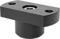
Arm Adapters—Add an arm adapter to mount your own custom-machined arm.
Clamps | Replacement Arms | Extended Arms | Arm Adapters | ||||||||||||||||||||||
|---|---|---|---|---|---|---|---|---|---|---|---|---|---|---|---|---|---|---|---|---|---|---|---|---|---|
Body | Holding Screw | Female Air Inlet and Outlet | |||||||||||||||||||||||
Max. Clamping Clearance | Vert. Travel During Rotation | Max. Clamping Stroke | Holding Cap., lb. | Reach Lg. | Thread Size | Thread Lg. | Sensor Ready | Overall Ht. | Thread Size | Tip Material | Pipe Size | Thread Size | Thread Type | Material | Each | Each | Lg. | Each | Each | ||||||
90° Clockwise Rotation | |||||||||||||||||||||||||
| 4" | 1 3/32" | 17/32" | 35 | 1 15/16" | M40 × 1.5 mm | 1 11/16" | Not Sensor Ready | 4 5/8" | M6 × 1 mm | Rubber | — | M5 × 0.8 mm | Metric | Aluminum | 9986N11 | 0000000 | 9986N17 | 000000 | — | ——— | 0 | 9986N18 | 000000 | ||
| 4 3/8" | 15/32" | 3/8" | 35 | 1 1/8" | 1 1/8"-16 | 2 7/8" | Sensor Ready | 4 3/4" | 10-32 | Steel | — | 10-32 | UNF | Aluminum | 50185A18 | 000000 | 50185A109 | 00000 | 2 7/8" | 50185A111 | 000000 | 50185A114 | 00000 | ||
| 4 9/16" | 1 1/8" | 17/32" | 100 | 2 9/16" | M55 × 1.5 mm | 2 1/4" | Not Sensor Ready | 5 1/4" | M8 × 1.25 mm | Rubber | 1/8 | — | BSPP | Aluminum | 9986N12 | 000000 | 50185A106 | 00000 | — | ——— | 0 | 50185A108 | 00000 | ||
| 5 5/16" | 3/4" | 1/2" | 95 | 1 5/8" | 1 3/4"-12 | 3 1/4" | Sensor Ready | 6 1/8" | 3/8"-16 | Rubber | 1/8 | — | NPT | Aluminum | 50185A15 | 000000 | 50185A112 | 00000 | — | ——— | 0 | ——— | 0 | ||
90° Counterclockwise Rotation | |||||||||||||||||||||||||
| 4" | 1 3/32" | 17/32" | 35 | 1 15/16" | M40 × 1.5 mm | 1 11/16" | Not Sensor Ready | 4 5/8" | M6 × 1 mm | Rubber | — | M5 × 0.8 mm | Metric | Aluminum | 9986N13 | 000000 | 9986N17 | 00000 | — | ——— | 0 | 9986N18 | 00000 | ||
| 4 3/8" | 15/32" | 3/8" | 35 | 1 1/8" | 1 1/8"-16 | 2 7/8" | Sensor Ready | 4 3/4" | 10-32 | Steel | — | 10-32 | UNF | Aluminum | 50185A19 | 000000 | 50185A109 | 00000 | 2 7/8" | 50185A111 | 00000 | 50185A114 | 00000 | ||
| 4 9/16" | 1 1/8" | 17/32" | 100 | 2 9/16" | M55 × 1.5 mm | 2 1/4" | Not Sensor Ready | 5 1/4" | M8 × 1.25 mm | Rubber | 1/8 | — | BSPP | Aluminum | 9986N14 | 000000 | 50185A106 | 00000 | — | ——— | 0 | 50185A108 | 00000 | ||
| 5 5/16" | 3/4" | 1/2" | 95 | 1 5/8" | 1 3/4"-12 | 3 1/4" | Sensor Ready | 6 1/8" | 3/8"-16 | Rubber | 1/8 | — | NPT | Aluminum | 50185A16 | 000000 | 50185A112 | 00000 | — | ——— | 0 | ——— | 0 | ||
 |
For Max. Clamping Clearance | Includes | Each | ||
|---|---|---|---|---|
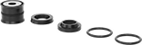
| 4 3/8" | Rod Seal, Rod Wiper, End Cap Seal, Retaining Ring, Aluminum Piston with a Molded Seal and Groove with a Magnetic Ring | 50185A116 | 000000 | |
| 5 5/16" | Rod Seal, Rod Wiper, End Cap Seal, Retaining Ring, Aluminum Piston with a Molded Seal and Groove with a Magnetic Ring | 9986N19 | 000000 |

Long-Life Dual-Mount Air-Powered Hold-Down Toggle Clamps
 |
These clamps have double the service life of other air-powered toggle clamps. Use for repetitive clamping and in production environments. They have two sets of holes for mounting on the bottom or side. Air from one inlet port engages the clamp, and air from the other inlet port disengages it. Clamps maintain the full-rated holding capacity even with a loss of air pressure. Capacity decreases by as much as 65% when mounting at the end of the arm. Fittings (not included) are required to connect the clamp’s ports to a control valve and an air line.
Arm | When Clamped | Air Inlet and Outlet | ||||||||||||||
|---|---|---|---|---|---|---|---|---|---|---|---|---|---|---|---|---|
Holding Cap., lb. | Max. Clamping Clearance | Ht. | Lg. | Opening Angle | Overall Lg. | Overall Ht. | Max. Air Inlet Pressure, psi | Thread Size | Thread Type | Gender | Temp. Range, ° F | Body Material | Each | |||
With Solid Arm | ||||||||||||||||
| 220 | 3/16" | 3/16" | 1 9/16" | 120° | 2 1/2" | 4 1/16" | 87 | M5 | Metric | Male | -14 to 194 | 6061 Aluminum | 2489N1 | 0000000 | ||
| 530 | 1/4" | 1/4" | 2" | 120° | 3" | 4 11/16" | 87 | M5 | Metric | Male | -14 to 194 | 6061 Aluminum | 2489N2 | 000000 | ||
| 885 | 3/8" | 3/8" | 2 1/8" | 120° | 3 1/2" | 5 15/16" | 87 | M5 | Metric | Male | -14 to 194 | 6061 Aluminum | 2489N3 | 000000 | ||
Air-Powered Hold-Down Fixture Clamps for Welding
 |  |
Rubber Holding Screw Tip | Steel Holding Screw Tip |
|  |
Extended Clamping Arm | 3 3/4" Lg. Extended Arms |
| |
Clamping Arm Adapter |
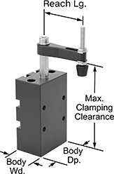
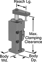
Compact and lightweight, these clamps are easy to move and reposition when welding. Adjust the air pressure to quickly and consistently clamp or release parts. When pressure is applied, the arm on these clamps rotates 90° into position over your workpiece before clamping down. When pressure is released, the arm rises and rotates out of the way, so you can load or unload parts. They’re also known as swing clamps. Attach a sensor (not included) to activate relays and controllers. Connect their ports to a control valve and an air line. Use screws (not included) to mount the base to a flat surface.
All clamps come with a holding screw.
Rubber Holding Screw Tip—Screws with a rubber tip are nonmarring, and their tip is removable.
Replacement Arms—Replacement arms (sold separately) do not include a holding screw. Extended arms (sold separately) give your clamp a longer reach than standard arms. However, you’ll have to use lower pressure, which means the actual clamping force will be lower than the clamp’s listed rating.
Arm Adapters—Add an arm adapter to mount your own custom-machined arm.
Clamps | Replacement Arms | Extended Arms | Arm Adapters | |||||||||||||||||||||||||
|---|---|---|---|---|---|---|---|---|---|---|---|---|---|---|---|---|---|---|---|---|---|---|---|---|---|---|---|---|
Body | Holding Screw | Female Air Inlet and Outlet | Mounting Holes | |||||||||||||||||||||||||
Max. Clamping Clearance | Vert. Travel During Rotation | Max. Clamping Stroke | Holding Cap., lb. | Reach Lg. | Wd. | Dp. | Thread Size | Tip Material | Pipe Size | Thread Size | Thread Type | No. of | Dia. | Thread Size | Dp. | Location | Material | Each | Each | Lg. | Each | Each | ||||||
90° Clockwise Rotation | ||||||||||||||||||||||||||||
| 3 5/8" | 21/32" | 5/16" | 20 | 1 5/8" | 1 1/8" | 1 5/8" | M4 × 0.7 mm | Rubber | — | M5 × 0.8 mm | Metric | 4 2 | — | M5 × 0.8 mm M5 × 0.8 mm | — 9/16" | Side Base | Aluminum | 50185A101 | 0000000 | 50185A105 | 000000 | — | ——— | 0 | 50185A107 | 000000 | ||
| 4 3/8" | 15/32" | 3/8" | 35 | 1 1/8" | 1 1/4" | 1 1/4" | 10-32 | Steel | — | 10-32 | UNF | 4 2 | 3/16" 3/16" | — | — | Side Base | Aluminum | 50185A51 | 000000 | 50185A109 | 00000 | 2 7/8" | 50185A111 | 000000 | 50185A114 | 00000 | ||
| 4 7/8" | 1 3/16" | 9/16" | 100 | 2 9/16" | 2 3/16" | 2 3/4" | M8 × 1.25 mm | Rubber | 1/8 | — | BSPP | 4 4 2 | — | M8 × 1.25 mm M8 × 1.25 mm M8 × 1.25 mm | 3/4" 9/16" 9/16" | Base Side Side | Aluminum | 50185A102 | 000000 | 50185A106 | 00000 | — | ——— | 0 | 50185A108 | 00000 | ||
| 5 1/2" | 3/4" | 1/2" | 130 | 2" | 2" | 3" | 3/8"-16 | Rubber | 1/8 | — | NPT | 4 2 | 11/32" 11/32" | — | — | Side Base | Aluminum | 50185A33 | 000000 | 50185A112 | 00000 | 3 3/4" | 50185A113 | 00000 | 50185A115 | 00000 | ||
90° Counterclockwise Rotation | ||||||||||||||||||||||||||||
| 3 5/8" | 21/32" | 5/16" | 20 | 1 5/8" | 1 1/8" | 1 5/8" | M4 × 0.7 mm | Rubber | — | M5 × 0.8 mm | Metric | 4 2 | — | M5 × 0.8 mm M5 × 0.8 mm | — 9/16" | Side Base | Aluminum | 50185A103 | 000000 | 50185A105 | 00000 | — | ——— | 0 | 50185A107 | 00000 | ||
| 4 3/8" | 15/32" | 3/8" | 35 | 1 1/8" | 1 1/4" | 1 1/4" | 10-32 | Steel | — | 10-32 | UNF | 4 2 | 3/16" 3/16" | — | — | Side Base | Aluminum | 50185A52 | 000000 | 50185A109 | 00000 | 2 7/8" | 50185A111 | 00000 | 50185A114 | 00000 | ||
| 4 7/8" | 1 3/16" | 9/16" | 100 | 2 9/16" | 2 3/16" | 2 3/4" | M8 × 1.25 mm | Rubber | 1/8 | — | BSPP | 4 4 2 | — | M8 × 1.25 mm M8 × 1.25 mm M8 × 1.25 mm | 3/4" 9/16" 9/16" | Base Side Side | Aluminum | 50185A104 | 000000 | 50185A106 | 00000 | — | ——— | 0 | 50185A108 | 00000 | ||
| 5 1/2" | 3/4" | 1/2" | 130 | 2" | 2" | 3" | 3/8"-16 | Rubber | 1/8 | — | NPT | 4 2 | 11/32" 11/32" | — | — | Side Base | Aluminum | 50185A34 | 000000 | 50185A112 | 00000 | 3 3/4" | 50185A113 | 00000 | 50185A115 | 00000 | ||
|
For Max. Clamping Clearance | Includes | Each | ||
|---|---|---|---|---|
| 4 3/8" | Rod Seal, Rod Wiper, End Cap Seal, Retaining Ring, Aluminum Piston with a Molded Seal and Groove with a Magnetic Ring | 50185A116 | 000000 | |
| 5 1/2" | Rod Seal, Rod Wiper, End Cap Seal, Retaining Ring, Aluminum Piston with a Molded Seal and Groove with a Magnetic Ring | 50185A117 | 00000 |
Dual-Mount Air-Powered Hold-Down Toggle Clamps
 |
Two sets of holes allow mounting on the bottom or side. Use these clamps for repetitive clamping and in production environments. Air from one inlet port engages the clamp, and air from the other inlet port disengages it. Clamps maintain the full-rated holding capacity even with a loss of air pressure. They have an open arm, so you can move the holding screw to any position along the arm. To achieve maximum holding capacity, position the screw closest to the base. Capacity decreases by as much as 65% when the screw is positioned at the end of the arm. Fittings (not included) are required to connect the clamp’s ports to a control valve and an air line.
Arm | When Clamped | Holding Screws | Air Inlet and Outlet | ||||||||||||||||
|---|---|---|---|---|---|---|---|---|---|---|---|---|---|---|---|---|---|---|---|
Holding Cap., lb. | Max. Clamping Clearance | Ht. | Lg. | Opening Angle | Overall Lg. | Overall Ht. | No. of | Tip Material | Thread Size | Max. Air Inlet Pressure, psi | Pipe Size | Thread Type | Gender | Temp. Range, ° F | Body Material | Each | |||
With Open Arm | |||||||||||||||||||
| 350 | 1 5/8" | 2 11/16" | 2 3/8" | 95° | 6 1/4" | 7 1/2" | 2 | Steel, Rubber | 5/16"-18 | 145 | 1/8 | NPT | Female | -14 to 194 | Steel | 2510N11 | 0000000 | ||
| 600 | 2 5/8" | 3 7/8" | 3 1/4" | 85° | 8 5/8" | 9" | 2 | Steel, Rubber | 3/8"-16 | 145 | 1/8 | NPT | Female | -14 to 194 | Steel | 2510N12 | 000000 | ||
Repair Kits for Kurt® Milling-Machine Vises
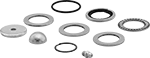 |
Maintain your vise by replacing seals, springs, and other commonly worn parts.
For Mfr. Model No. | No. of Pieces | Includes | Each | ||
|---|---|---|---|---|---|
| 3400, 3400V, 3410V | 10 | Internal Brush Seals (2) O-Rings (2) Segment (1) Spiral Retaining Rings (2) Thrust Bearing (1) Thrust Bearing Washers (2) | 2569N19 | 000000 | |
| 3600V, 3610V | 10 | Backer Ring (1) Internal Brush Seals (2) O-Ring (1) Segment (1) Spiral Retaining Rings (2) Thrust Bearing (1) Thrust Bearing Washers (2) | 2569N13 | 00000 | |
| D40 | 8 | Cap (1) O-Ring (1) Segment (1) Spiral Retaining Ring (1) Thrust Bearing (1) Thrust Bearing Washers (3) | 2569N18 | 00000 | |
| D60 | 7 | Cap (1) Segment (1) Spiral Retaining Ring (1) Thrust Bearing (1) Thrust Bearing Washers (3) | 2569N14 | 00000 | |
| D675 | 10 | Drive Type Grease Fitting (1) Internal Brush Seal (1) O-Ring (1) Plug/Grease Fitting (1) Segment (1) Spiral Retaining Ring (1) Thrust Bearing (1) Thrust Bearing Washers (3) | 2569N11 | 00000 | |
| D688 | 9 | Internal Brush Seals (2) O-Ring (1) Segment (1) Spiral Retaining Ring (1) Thrust Bearing (1) Thrust Bearing Washers (3) | 2569N12 | 00000 | |
| DL640 | 17 | Clutch Springs (3) O-Rings (3) Pin/Dowel (1) Preloaded Spring (1) Retaining Rings (2) Snap Ring (1) Thrust Bearing (1) Thrust Bearing Washers (3) Wiper Ring Seals (2) | 2569N17 | 00000 | |
| DX4 | 10 | Internal Brush Seals (2) O-Ring (1) Spiral Retaining Rings (2) Thrust Bearing (1) Thrust Bearing Washers (2) Wave Springs (2) | 2569N31 | 00000 | |
| DX6 | 11 | Internal Brush Seals (2) O-Rings (2) Spiral Retaining Rings (2) Thrust Bearing (1) Thrust Bearing Washers (2) Wave Springs (2) | 2569N21 | 00000 | |
| HDL6, HDLM6 | 17 | Clutch Springs (3) Dowel Pin (1) O-Rings (3) Preloaded Spring (1) Retaining Rings (2) Snap Ring (1) Thrust Bearing (1) Thrust Bearing Washers (3) Wiper Ring (1) Wiper Ring Seal (1) | 2569N16 | 00000 |
