


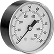
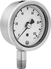
Find a gauge with the right connection material and dial type—many with traceable calibration certificates.
Pressure Gauges
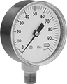 |  |  |  |
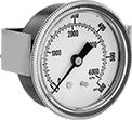
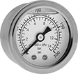
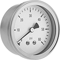
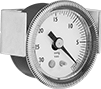
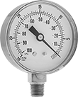
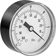
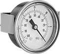
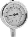
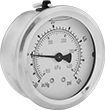
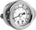
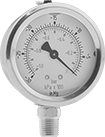
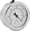
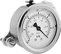
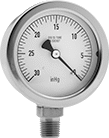
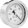
Bottom Connection | Bottom Connection with Rubber Cover | Center-Back Connection | Center-Back Connection (Panel Mount) |
 |  |  | |
Bottom Connection | Bottom Connection with Rubber Cover | Center-Back Connection | Center-Back Connection (Panel Mount) |
Temp. Range, ° F | Bottom Connection | Bottom Connection with Rubber Cover | Center-Back Connection | Center-Back Connection (Panel Mount) | ||||||||||||||
|---|---|---|---|---|---|---|---|---|---|---|---|---|---|---|---|---|---|---|
Dial Dia. | Pipe Size | Case Color | Environment | Process | For Use With | Accuracy | Choose a Pressure Range | Each | Each | Each | For Panel Cutout Dia. | Each | ||||||
Any-Angle Mount | ||||||||||||||||||
NPT Male | ||||||||||||||||||
| 1 1/2" | 1/8 | Black | -40 to 150 | -40 to 150 | Air Ethyl Alcohol Hydraulic Fluid Natural Gas Nitrogen Water | ±2% Midscale (Grade B) | 0 to 15 psi; 0 to 30 psi; 0 to 60 psi; 0 to 100 psi; 0 to 160 psi; 0 to 200 psi; 0 to 300 psi; 0 to 400 psi; 0 to 600 psi; 0 to 1,000 psi | 3847K71 | 000000 | 2201T23 | 000000 | 3847K72 | 000000 | 1 31/32" | 3847K73 | 000000 | ||
NPT Male with Calibration Certificate Traceable to NIST | ||||||||||||||||||
| 1 1/2" | 1/8 | Black | -40 to 150 | -40 to 150 | Air Ethyl Alcohol Hydraulic Fluid Natural Gas Nitrogen Water | ±2% Midscale (Grade B) | 0 to 15 psi; 0 to 30 psi; 0 to 60 psi; 0 to 100 psi; 0 to 160 psi; 0 to 200 psi; 0 to 300 psi; 0 to 400 psi; 0 to 600 psi; 0 to 1,000 psi | 9796T11 | 000000 | 2201T31 | 000000 | 9796T12 | 000000 | 1 31/32" | 9796T13 | 000000 | ||
| | | |
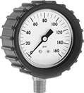
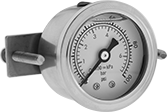
Bottom Connection | Bottom Connection with Rubber Cover | Center-Back Connection | Center-Back Connection (Panel Mount) |
| | | |
Bottom Connection | Bottom Connection with Rubber Cover | Center-Back Connection | Center-Back Connection (Panel Mount) |
Temp. Range, ° F | Bottom Connection | Bottom Connection with Rubber Cover | Center-Back Connection | Center-Back Connection (Panel Mount) | |||||||||||||
|---|---|---|---|---|---|---|---|---|---|---|---|---|---|---|---|---|---|
Dial Dia. | Pipe Size | Environment | Process | For Use With | Accuracy | Choose a Pressure Range | Each | Each | Each | For Panel Cutout Dia. | Each | ||||||
Any-Angle Mount | |||||||||||||||||
NPT Male | |||||||||||||||||
| 1 1/2" | 1/8 | -40 to 150 | -40 to 150 | Air Ethyl Alcohol Hydraulic Fluid Natural Gas Nitrogen Water | ±2% Midscale (Grade B) | 0 to 15 psi; 0 to 30 psi; 0 to 60 psi; 0 to 100 psi; 0 to 160 psi; 0 to 200 psi; 0 to 300 psi; 0 to 400 psi; 0 to 600 psi; 0 to 1,000 psi | 3846K1 | 000000 | 2201T39 | 000000 | 3846K2 | 000000 | 1 3/4" | 3846K4 | 000000 | ||
 |  |  |  |
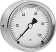
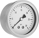
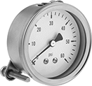
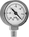
Bottom Connection | Bottom Connection with Rubber Cover | Center-Back Connection | Center-Back Connection (Panel Mount) |
| | | |
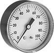
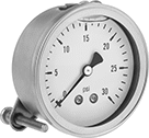
Bottom Connection | Bottom Connection with Rubber Cover | Center-Back Connection | Center-Back Connection (Panel Mount) |
Temp. Range, ° F | Bottom Connection | Bottom Connection with Rubber Cover | Center-Back Connection | Center-Back Connection (Panel Mount) | |||||||||||||
|---|---|---|---|---|---|---|---|---|---|---|---|---|---|---|---|---|---|
Dial Dia. | Pipe Size | Environment | Process | For Use With | Accuracy | Choose a Pressure Range | Each | Each | Each | For Panel Cutout Dia. | Each | ||||||
Any-Angle Mount | |||||||||||||||||
NPT Male | |||||||||||||||||
| 1 1/2" | 1/8 | -40 to 150 | -40 to 150 | Air Ethyl Alcohol Hydraulic Fluid Natural Gas Nitrogen Water | ±2% Midscale (Grade B) | 0 to 15 psi/0 to 100 kPa; 0 to 30 psi/0 to 200 kPa; 0 to 60 psi/0 to 400 kPa; 0 to 100 psi/0 to 700 kPa; 0 to 160 psi/0 to 1,100 kPa; 0 to 200 psi/0 to 1,400 kPa; 0 to 300 psi/0 to 2,000 kPa; 0 to 400 psi/0 to 2,800 kPa; 0 to 600 psi/0 to 4,000 kPa; 0 to 1,000 psi/0 to 7,000 kPa | 4000K717 | 000000 | 2201T51 | 000000 | 4000K718 | 000000 | 1 3/4" | 4000K719 | 000000 | ||
| |
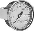
Center-Back Connection | Center-Back Connection |
Temp. Range, ° F | Center-Back Connection | |||||||||
|---|---|---|---|---|---|---|---|---|---|---|
Dial Dia. | Pipe Size | Environment | Process | For Use With | Accuracy | Choose a Pressure Range | Each | |||
Any-Angle Mount | ||||||||||
NPT Male | ||||||||||
| 1 1/2" | 1/8 | -4 to 140 | -4 to 140 | Air Ethyl Alcohol Hydraulic Fluid Natural Gas Nitrogen Water | ±2.5% Full Scale (Not Rated) | 0 to 60 psi, 0 to 100 psi, 0 to 160 psi, 0 to 200 psi, 0 to 300 psi | 40565K592 | 000000 | ||
| 1 1/2" | 1/8 | -4 to 140 | -4 to 140 | Air Ethyl Alcohol Hydraulic Fluid Natural Gas Nitrogen Water | ±2.5% Full Scale (Not Rated) | 0 to 800 psi, 0 to 1,500 psi, 0 to 2,000 psi, 0 to 3,000 psi, 0 to 4,000 psi | 40565K684 | 00000 | ||
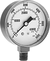
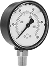
Vibration-Resistant Pressure Gauges
 | |
Center-Back Connection | Center-Back Connection |
Temp. Range, ° F | Center-Back Connection | |||||||||||
|---|---|---|---|---|---|---|---|---|---|---|---|---|
Dial Dia. | Pipe Size | Case Color | Environment | Process | Liquid Type | For Use With | Accuracy | Choose a Pressure Range | Each | |||
Upright Mount | ||||||||||||
NPT Male | ||||||||||||
| 1 1/2" | 1/8 | Black | 0 to 140 | 0 to 140 | Glycerin | Air Carbon Dioxide Hydraulic Fluid Natural Gas Water | ±2.5% Full Scale (Not Rated) | 0 to 30 psi, 0 to 60 psi, 0 to 100 psi, 0 to 160 psi, 0 to 300 psi, 0 to 2,000 psi, 0 to 3,000 psi, 0 to 5,000 psi | 38055K21 | 000000 | ||
 |  | | |
Bottom Connection | Center-Back Connection | Bottom Connection | Center-Back Connection |
Bottom Connection | Center-Back Connection | |||||||||||
|---|---|---|---|---|---|---|---|---|---|---|---|---|
Dial Dia. | Pipe Size | Environment Temp. Range, ° F | Liquid Type | For Use With | Accuracy | Choose a Pressure Range | Each | Each | ||||
Upright Mount | ||||||||||||
NPT Male | ||||||||||||
| 1 1/2" | 1/8 | 40 to 140 | Glycerin | Air Hydraulic Fluid Water | ±1% Midscale (Grade A) | 0 to 15 psi/0 to 100 kPa; 0 to 30 psi/0 to 200 kPa; 0 to 60 psi/0 to 400 kPa; 0 to 100 psi/0 to 680 kPa; 0 to 160 psi/0 to 1,100 kPa; 0 to 200 psi/0 to 1,400 kPa; 0 to 300 psi/0 to 2,000 kPa; 0 to 400 psi/0 to 2,700 kPa; 0 to 600 psi/0 to 4,000 kPa; 0 to 1,000 psi/0 to 6,800 kPa; 0 to 2,000 psi/0 to 13,500 kPa; 0 to 3,000 psi/0 to 20,000 kPa; 0 to 5,000 psi/0 to 34,000 kPa | 3850K2 | 000000 | ——— | 0 | ||
| 1 1/2" | 1/8 | 40 to 140 | Glycerin | Air Hydraulic Fluid Water | ±1% Midscale (Grade A) | 0 to 15 psi/0 to 100 kPa; 0 to 30 psi/0 to 200 kPa; 0 to 60 psi/0 to 400 kPa; 0 to 100 psi/0 to 680 kPa; 0 to 160 psi/0 to 1,100 kPa; 0 to 200 psi/0 to 1,400 kPa; 0 to 300 psi/0 to 2,000 kPa; 0 to 600 psi/0 to 4,000 kPa; 0 to 1,000 psi/0 to 6,800 kPa; 0 to 1,500 psi/0 to 10,000 kPa; 0 to 2,000 psi/0 to 13,500 kPa; 0 to 3,000 psi/0 to 20,000 kPa; 0 to 5,000 psi/0 to 34,000 kPa | ——— | 0 | 3850K3 | 000000 | ||
|  | | |
Center-Back Connection | Center-Back Connection (Panel Mount) | Center-Back Connection | Center-Back Connection (Panel Mount) |
Temp. Range, ° F | Center-Back Connection | Center-Back Connection (Panel Mount) | ||||||||||||
|---|---|---|---|---|---|---|---|---|---|---|---|---|---|---|
Dial Dia. | Pipe Size | Environment | Process | Liquid Type | For Use With | Accuracy | Choose a Pressure Range | Each | For Panel Cutout Dia. | Each | ||||
Upright Mount | ||||||||||||||
NPT Male | ||||||||||||||
| 1 1/2" | 1/8 | -20 to 160 | -20 to 160 | Silicone | Air Hydraulic Fluid Natural Gas Water | ±2% Midscale (Grade B) | 0 to 15 psi/0 to 100 kPa; 0 to 30 psi/0 to 200 kPa; 0 to 60 psi/0 to 400 kPa; 0 to 100 psi/0 to 700 kPa; 0 to 160 psi/0 to 1,100 kPa; 0 to 200 psi/0 to 1,400 kPa; 0 to 300 psi/0 to 2,000 kPa; 0 to 600 psi/0 to 4,000 kPa; 0 to 1,000 psi/0 to 7,000 kPa; 0 to 1,500 psi/0 to 10,000 kPa; 0 to 2,000 psi/0 to 14,000 kPa; 0 to 3,000 psi/0 to 20,000 kPa; 0 to 5,000 psi/0 to 35,000 kPa | 9780T11 | 000000 | 1 5/8" | 9780T21 | 000000 | ||
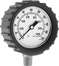
Vibration- and Corrosion-Resistant Pressure Gauges
 |  |  | | | |
Bottom Connection | Center-Back Connection | Center-Back Connection (Panel Mount) | Bottom Connection | Center-Back Connection | Center-Back Connection (Panel Mount) |
Temp. Range, ° F | Bottom Connection | Center-Back Connection | Center-Back Connection (Panel Mount) | ||||||||||||||
|---|---|---|---|---|---|---|---|---|---|---|---|---|---|---|---|---|---|
Dial Dia. | Pipe Size | Environment | Process | Mounting Position | Liquid Type | For Use With | Accuracy | Choose a Pressure Range | Each | Each | For Panel Cutout Dia. | Each | |||||
NPT Male | |||||||||||||||||
| 1 1/2" | 1/8 | 20 to 150 | 20 to 200 | Any Angle | Glycerin | Air Diesel Fuel Gasoline Hydraulic Fluid Natural Gas Water | ±2% Midscale (Grade B) | 0 to 15 psi; 0 to 30 psi; 0 to 60 psi; 0 to 100 psi; 0 to 160 psi; 0 to 200 psi; 0 to 300 psi; 0 to 400 psi; 0 to 600 psi; 0 to 1,000 psi; 0 to 2,000 psi; 0 to 3,000 psi; 0 to 4,000 psi; 0 to 5,000 psi | 3795K11 | 000000 | 3795K12 | 000000 | 1 11/16" | 3795K74 | 0000000 | ||
Corrosion-Resistant Pressure Gauges
 |  |  | | | |
Bottom Connection | Center-Back Connection | Center-Back Connection (Panel Mount) | Bottom Connection | Center-Back Connection | Center-Back Connection (Panel Mount) |
Temp. Range, ° F | Bottom Connection | Center-Back Connection | Center-Back Connection (Panel Mount) | ||||||||||||
|---|---|---|---|---|---|---|---|---|---|---|---|---|---|---|---|
Dial Dia. | Pipe Size | Environment | Process | For Use With | Accuracy | Choose a Pressure Range | Each | Each | For Panel Cutout Dia. | Each | |||||
Any-Angle Mount | |||||||||||||||
NPT Male | |||||||||||||||
| 1 1/2" | 1/8 | 0 to 200 | 0 to 200 | Air Diesel Fuel Gasoline Hydraulic Fluid Natural Gas Water | ±2% Midscale (Grade B) | 0 to 15 psi; 0 to 30 psi; 0 to 60 psi; 0 to 100 psi; 0 to 160 psi; 0 to 200 psi; 0 to 300 psi; 0 to 400 psi; 0 to 600 psi; 0 to 1,000 psi; 0 to 2,000 psi; 0 to 3,000 psi; 0 to 4,000 psi; 0 to 5,000 psi | 4066K21 | 000000 | 4066K31 | 000000 | 1 11/16" | 4066K81 | 0000000 | ||
Vacuum Gauges
 |  |  | | | |
Bottom Connection | Center-Back Connection | Center-Back Connection (Panel Mount) | Bottom Connection | Center-Back Connection | Center-Back Connection (Panel Mount) |
Available Vacuum Ranges, in. Hg | Bottom Connection | Center-Back Connection | Center-Back Connection (Panel Mount) | |||||||||||||||
|---|---|---|---|---|---|---|---|---|---|---|---|---|---|---|---|---|---|---|
Dial Dia. | Pipe Size | Environment Temp. Range, ° F | Process Temp. Range, ° F | Case Color | Vacuum Range | Graduations | Pressure Numeric Increments | For Use With | Accuracy | Each | Each | For Panel Cutout Dia. | Each | |||||
NPT Male | ||||||||||||||||||
| 1 1/2" | 1/8 | -40 to 150 | -40 to 150 | Black | -30 to 0 | 0.5 | 5 | Air | ±2% Midscale (Grade B) | 4002K15 | 000000 | 4002K35 | 000000 | 1 3/4" | 4002K25 | 000000 | ||
NPT Male with Calibration Certificate Traceable to NIST | ||||||||||||||||||
| 1 1/2" | 1/8 | -40 to 150 | -40 to 150 | Black | -30 to 0 | 0.5 | 5 | Air | ±2% Midscale (Grade B) | 4002K138 | 00000 | 4002K137 | 00000 | — | ——— | 0 | ||
 |  |  | | | |
Bottom Connection | Center-Back Connection | Center-Back Connection (Panel Mount) | Bottom Connection | Center-Back Connection | Center-Back Connection (Panel Mount) |
Available Vacuum Ranges | Bottom Connection | Center-Back Connection | Center-Back Connection (Panel Mount) | |||||||||||||||
|---|---|---|---|---|---|---|---|---|---|---|---|---|---|---|---|---|---|---|
Dial Dia. | Pipe Size | Environment Temp. Range, ° F | Process Temp. Range, ° F | Case Color | Vacuum Range | Graduations | Pressure Numeric Increments | For Use With | Accuracy | Each | Each | For Panel Cutout Dia. | Each | |||||
NPT Male | ||||||||||||||||||
| 1 1/2" | 1/8 | -40 to 150 | -40 to 150 | Black | -30 in. Hg to 0 in. Hg -100 kPa to 0 kPa | 0.5 in. Hg 2 kPa | 5 in. Hg 10 kPa | Air | ±2% Midscale (Grade B) | 4002K111 | 000000 | 4002K112 | 000000 | 1 3/4" | 4002K113 | 000000 | ||
NPT Male with Calibration Certificate Traceable to NIST | ||||||||||||||||||
| 1 1/2" | 1/8 | -40 to 150 | -40 to 150 | Black | -30 in. Hg to 0 in. Hg -100 kPa to 0 kPa | 0.5 in. Hg 2 kPa | 5 in. Hg 10 kPa | Air | ±2% Midscale (Grade B) | 4002K124 | 00000 | 4002K125 | 00000 | — | ——— | 0 | ||
| | | |
Bottom Connection | Center-Back Connection | Bottom Connection | Center-Back Connection |
Available Vacuum Ranges, in. Hg | Bottom Connection | Center-Back Connection | |||||||||||||
|---|---|---|---|---|---|---|---|---|---|---|---|---|---|---|---|
Dial Dia. | Pipe Size | Environment Temp. Range, ° F | Process Temp. Range, ° F | Case Color | Vacuum Range | Graduations | Pressure Numeric Increments | For Use With | Accuracy | Each | Each | ||||
NPT Male | |||||||||||||||
| 1 1/2" | 1/8 | -40 to 140 | -40 to 140 | Black | -30 to 0 | 0.5 | 5 | Air | ±2% Midscale (Grade B) | 3935K11 | 000000 | 3935K21 | 000000 | ||
| | | |
Bottom Connection | Center-Back Connection | Bottom Connection | Center-Back Connection |
Available Vacuum Ranges | Bottom Connection | Center-Back Connection | |||||||||||||
|---|---|---|---|---|---|---|---|---|---|---|---|---|---|---|---|
Dial Dia. | Pipe Size | Environment Temp. Range, ° F | Process Temp. Range, ° F | Case Color | Vacuum Range | Graduations | Pressure Numeric Increments | For Use With | Accuracy | Each | Each | ||||
NPT Male | |||||||||||||||
| 1 1/2" | 1/8 | -40 to 140 | -40 to 140 | Black | -30 in. Hg to 0 in. Hg -100 kPa to 0 kPa | 0.5 in. Hg 2 kPa | 5 in. Hg 10 kPa | Air | ±2% Midscale (Grade B) | 3935K33 | 000000 | 3935K34 | 000000 | ||
Vibration- and Corrosion-Resistant Pressure and Vacuum Gauges
 |  |  | | | |
Dual Scale, Bottom Connection | Dual Scale, Center-Back Connection | Dual Scale, Center-Back Connection (Panel Mount) | Bottom Connection | Center-Back Connection | Center-Back Connection (Panel Mount) |
Bottom Connection | Center-Back Connection | Center-Back Connection (Panel Mount) | ||||||||||||||||||
|---|---|---|---|---|---|---|---|---|---|---|---|---|---|---|---|---|---|---|---|---|
Dial Dia. | Pipe Size | Environment Temp. Range, ° F | Process Temp. Range, ° F | Lens Material | Liquid Type | Pressure | Vacuum | Graduations | Pressure Numeric Increments | For Use With | Accuracy | Each | Each | For Panel Cutout Dia. | Each | |||||
304 Stainless Steel Case with Brass Connection—Dual Scale (Inches of Mercury, Kilopascals, Pounds per Square Inch) | ||||||||||||||||||||
NPT Male | ||||||||||||||||||||
| 1 1/2" | 1/8 | 35 to 140 | 35 to 140 | Polycarbonate | Glycerin | 0 psi to 15 psi; 0 kPa to 100 kPa | -100 in. Hg to 30 in. Hg, 0 in. Hg to 30 in. Hg, -100 kPa to 0 kPa | 1 in. Hg, 1 psi, 5 kPa | 10 in. Hg, 5 psi, 50 kPa | Air, Water | ±1% Midscale (Grade A) | ——— | 0 | 38545K52 | 000000 | 1 39/64" | 38545K113 | 000000 | ||
| 1 1/2" | 1/8 | 35 to 140 | 35 to 140 | Polycarbonate | Glycerin | 0 psi to 15 psi; 0 kPa to 100 kPa | -100 in. Hg to 30 in. Hg, 0 in. Hg to 30 in. Hg, -100 kPa to 0 kPa | 1 in. Hg, 0.5 psi, 5 kPa | 10 in. Hg, 5 psi, 50 kPa | Air, Water | ±2.5% Full Scale | 38545K42 | 000000 | ——— | 0 | — | ——— | 0 | ||
| 1 1/2" | 1/8 | 35 to 140 | 35 to 140 | Polycarbonate | Glycerin | 0 psi to 30 psi; 0 kPa to 200 kPa | -100 in. Hg to 30 in. Hg, 0 in. Hg to 30 in. Hg, -100 kPa to 0 kPa | 1 in. Hg, 1 psi, 5 kPa | 10 in. Hg, 10 psi, 50 kPa | Air, Water | ±1% Midscale (Grade A) | ——— | 0 | 38545K53 | 00000 | 1 39/64" | 38545K114 | 00000 | ||
| 1 1/2" | 1/8 | 35 to 140 | 35 to 140 | Polycarbonate | Glycerin | 0 psi to 30 psi; 0 kPa to 200 kPa | -100 in. Hg to 30 in. Hg, 0 in. Hg to 30 in. Hg, -100 kPa to 0 kPa | 2 in. Hg, 1 psi, 5 kPa | 10 in. Hg, 10 psi, 50 kPa | Air, Water | ±2.5% Full Scale | 38545K43 | 00000 | ——— | 0 | — | ——— | 0 | ||
| 1 1/2" | 1/8 | 35 to 140 | 35 to 140 | Polycarbonate | Glycerin | 0 psi to 60 psi; 0 kPa to 400 kPa | -100 in. Hg to 30 in. Hg, 0 in. Hg to 30 in. Hg, -100 kPa to 0 kPa | 2 in. Hg, 1 psi, 10 kPa | 10 in. Hg, 10 psi, 100 kPa | Air, Water | ±1% Midscale (Grade A) | ——— | 0 | 38545K54 | 00000 | 1 39/64" | 38545K115 | 00000 | ||
| 1 1/2" | 1/8 | 35 to 140 | 35 to 140 | Polycarbonate | Glycerin | 0 psi to 60 psi; 0 kPa to 400 kPa | -100 in. Hg to 30 in. Hg, 0 in. Hg to 30 in. Hg, -100 kPa to 0 kPa | 2 in. Hg, 2 psi, 10 kPa | 30 in. Hg, 20 psi, 100 kPa | Air, Water | ±2.5% Full Scale | 38545K44 | 00000 | ——— | 0 | — | ——— | 0 | ||
| 1 1/2" | 1/8 | 35 to 140 | 35 to 140 | Polycarbonate | Glycerin | 0 psi to 100 psi; 0 kPa to 700 kPa | -100 in. Hg to 30 in. Hg, 0 in. Hg to 30 in. Hg, -100 kPa to 0 kPa | 2 psi, 5 in. Hg, 20 kPa | 30 in. Hg, 20 psi, 100 kPa | Air, Water | ±1% Midscale (Grade A) | ——— | 0 | 38545K55 | 00000 | 1 39/64" | 38545K116 | 00000 | ||
| 1 1/2" | 1/8 | 35 to 140 | 35 to 140 | Polycarbonate | Glycerin | 0 psi to 100 psi; 0 kPa to 700 kPa | -100 in. Hg to 30 in. Hg, 0 in. Hg to 30 in. Hg, -100 kPa to 0 kPa | 2 psi, 6 in. Hg, 10 kPa | 30 in. Hg, 20 psi, 100 kPa | Air, Water | ±2.5% Full Scale | 38545K45 | 00000 | ——— | 0 | — | ——— | 0 | ||
| 1 1/2" | 1/8 | 35 to 140 | 35 to 140 | Polycarbonate | Glycerin | 0 psi to 150 psi; 0 kPa to 1,000 kPa | -100 in. Hg to 30 in. Hg, 0 in. Hg to 30 in. Hg, -100 kPa to 0 kPa | 2 psi, 5 in. Hg, 20 kPa | 30 in. Hg, 20 psi, 200 kPa | Air, Water | ±1% Midscale (Grade A) | ——— | 0 | 38545K56 | 00000 | 1 39/64" | 38545K112 | 00000 | ||
| 1 1/2" | 1/8 | 35 to 140 | 35 to 140 | Polycarbonate | Glycerin | 0 psi to 150 psi; 0 kPa to 1,000 kPa | -100 in. Hg to 30 in. Hg, 0 in. Hg to 30 in. Hg, -100 kPa to 0 kPa | 2 psi, 7.5 in. Hg, 20 kPa | 30 in. Hg, 30 psi, 200 kPa | Air, Water | ±2.5% Full Scale | 38545K46 | 00000 | ——— | 0 | — | ——— | 0 | ||
| 1 1/2" | 1/8 | 35 to 140 | 35 to 140 | Polycarbonate | Glycerin | 0 psi to 300 psi; 0 kPa to 2,000 kPa | -100 in. Hg to 30 in. Hg, 0 in. Hg to 30 in. Hg, -100 kPa to 0 kPa | 5 psi, 15 in. Hg, 50 kPa | 30 in. Hg, 50 psi, 500 kPa | Air, Water | ±2.5% Full Scale | 38545K48 | 00000 | ——— | 0 | — | ——— | 0 | ||
Vibration- and Corrosion-Resistant Vacuum Gauges
 |  |  | | | |
Bottom Connection | Center-Back Connection | Center-Back Connection (Panel Mount) | Bottom Connection | Center-Back Connection | Center-Back Connection (Panel Mount) |
Available Vacuum Ranges | Bottom Connection | Center-Back Connection | Center-Back Connection (Panel Mount) | |||||||||||||||
|---|---|---|---|---|---|---|---|---|---|---|---|---|---|---|---|---|---|---|
Dial Dia. | Pipe Size | Environment Temp. Range, ° F | Process Temp. Range, ° F | Liquid Type | Vacuum Range | Graduations | Pressure Numeric Increments | For Use With | Accuracy | Each | Each | For Panel Cutout Dia. | Each | |||||
NPT Male | ||||||||||||||||||
| 1 1/2" | 1/8 | 35 to 140 | 35 to 140 | Glycerin | -30 in. Hg to 0 in. Hg -100 kPa to 0 kPa | 0.5 in. Hg 2 kPa | 5 in. Hg 20 kPa | Air | ±1% Midscale (Grade A) | ——— | 0 | 38545K51 | 000000 | 1 39/64" | 38545K111 | 000000 | ||
| 1 1/2" | 1/8 | 35 to 140 | 35 to 140 | Glycerin | -30 in. Hg to 0 in. Hg -100 kPa to 0 kPa | 0.5 in. Hg 2 kPa | 5 in. Hg 20 kPa | Air | ±2.5% Full Scale | 38545K41 | 000000 | ——— | 0 | — | ——— | 0 | ||
Corrosion-Resistant Vacuum Gauges
 |  | | |
Bottom Connection | Center-Back Connection | Bottom Connection | Center-Back Connection |
Available Vacuum Ranges, in. Hg | Bottom Connection | Center-Back Connection | ||||||||||||
|---|---|---|---|---|---|---|---|---|---|---|---|---|---|---|
Dial Dia. | Pipe Size | Environment Temp. Range, ° F | Process Temp. Range, ° F | Vacuum Range | Graduations | Pressure Numeric Increments | For Use With | Accuracy | Each | Each | ||||
NPT Male | ||||||||||||||
| 1 1/2" | 1/8 | -40 to 200 | -40 to 250 | -30 to 0 | 0.5 | 5 | Air | ±2% Midscale (Grade B) | 3961K912 | 000000 | 3961K911 | 0000000 | ||
Compact Tension Force Gauges
 |
Cap. | Accuracy | Measuring Increments | Ht. | Wd. | Dp. | Dial Dia. | Container Type | Tip Shape | Each | |||
|---|---|---|---|---|---|---|---|---|---|---|---|---|
Aluminum Housing | ||||||||||||
| 0 g to 10 g | ±0.2 g | 0.2 g | 3 3/4" | 1 3/4" | 1" | 1 1/2" | Plastic Case | Flat | 1368T21 | 0000000 | ||
| 10 g to 50 g | ±1 g | 1 g | 3 3/4" | 1 3/4" | 1" | 1 1/2" | Plastic Case | Flat | 1368T3 | 000000 | ||
| 50 g to 150 g | ±5 g | 5 g | 3 3/4" | 1 3/4" | 1" | 1 1/2" | Plastic Case | Flat | 1368T52 | 000000 | ||
| 50 g to 250 g | ±10 g | 10 g | 3 3/4" | 1 3/4" | 1" | 1 1/2" | Plastic Case | Flat | 1368T62 | 000000 | ||
