


Find a gauge with the right connection material and dial type—many with traceable calibration certificates.
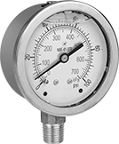
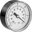
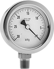
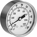
Pressure Gauges
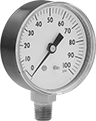 |  |  |  |
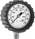
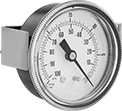
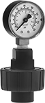
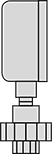
Bottom Connection | Bottom Connection with Rubber Cover | Center-Back Connection | Center-Back Connection (Panel Mount) |
 |  |  | |
Bottom Connection | Bottom Connection with Rubber Cover | Center-Back Connection | Center-Back Connection (Panel Mount) |
Temp. Range, ° F | Bottom Connection | Bottom Connection with Rubber Cover | Center-Back Connection | Center-Back Connection (Panel Mount) | ||||||||||||||
|---|---|---|---|---|---|---|---|---|---|---|---|---|---|---|---|---|---|---|
Dial Dia. | Pipe Size | Case Color | Environment | Process | For Use With | Accuracy | Choose a Pressure Range | Each | Each | Each | For Panel Cutout Dia. | Each | ||||||
Any-Angle Mount | ||||||||||||||||||
NPT Male | ||||||||||||||||||
| 2" | 1/4 | Black | -40 to 150 | -40 to 150 | Air Ethyl Alcohol Hydraulic Fluid Natural Gas Nitrogen Water | ±2% Midscale (Grade B) | 0 to 15 psi; 0 to 30 psi; 0 to 60 psi; 0 to 100 psi; 0 to 160 psi; 0 to 200 psi; 0 to 300 psi; 0 to 400 psi; 0 to 600 psi; 0 to 1,000 psi; 0 to 2,000 psi; 0 to 3,000 psi; 0 to 4,000 psi; 0 to 5,000 psi; 0 to 6,000 psi | 4089K61 | 000000 | 2201T25 | 000000 | 4089K62 | 000000 | 2 7/16" | 4089K63 | 000000 | ||
NPT Male with Calibration Certificate Traceable to NIST | ||||||||||||||||||
| 2" | 1/4 | Black | -40 to 150 | -40 to 150 | Air Ethyl Alcohol Hydraulic Fluid Natural Gas Nitrogen Water | ±2% Midscale (Grade B) | 0 to 15 psi; 0 to 30 psi; 0 to 60 psi; 0 to 100 psi; 0 to 160 psi; 0 to 200 psi; 0 to 300 psi; 0 to 400 psi; 0 to 600 psi; 0 to 1,000 psi; 0 to 2,000 psi; 0 to 3,000 psi; 0 to 4,000 psi; 0 to 5,000 psi; 0 to 6,000 psi | 9796T21 | 000000 | 2201T33 | 000000 | 9796T22 | 000000 | 2 7/16" | 9796T23 | 000000 | ||
 |  | | |
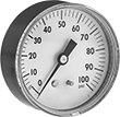
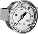
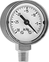
Bottom Connection | Center-Back Connection | Bottom Connection | Center-Back Connection |
Temp. Range, ° F | Bottom Connection | Center-Back Connection | |||||||||||
|---|---|---|---|---|---|---|---|---|---|---|---|---|---|
Dial Dia. | Pipe Size | Case Color | Environment | Process | For Use With | Accuracy | Choose a Pressure Range | Each | Each | ||||
Upright Mount | |||||||||||||
BSPT Male | |||||||||||||
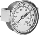
| 2" | 1/4 | Black | -40 to 120 | -40 to 120 | Air Carbon Dioxide Hydraulic Fluid Natural Gas Water | ±2% Midscale (Grade B) | 0 to 30 psi/0 to 200 kPa; 0 to 60 psi/0 to 400 kPa; 0 to 100 psi/0 to 700 kPa; 0 to 160 psi/0 to 1,100 kPa; 0 to 200 psi/0 to 1,400 kPa; 0 to 300 psi/0 to 2,000 kPa; 0 to 600 psi/0 to 4,000 kPa; 0 to 1,000 psi/0 to 7,000 kPa | 9804T52 | 000000 | 9804T62 | 000000 | ||
| | | |
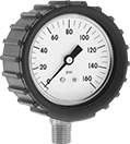
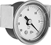
Bottom Connection | Bottom Connection with Rubber Cover | Center-Back Connection | Center-Back Connection (Panel Mount) |
| | | |
Bottom Connection | Bottom Connection with Rubber Cover | Center-Back Connection | Center-Back Connection (Panel Mount) |
Temp. Range, ° F | Bottom Connection | Bottom Connection with Rubber Cover | Center-Back Connection | Center-Back Connection (Panel Mount) | |||||||||||||
|---|---|---|---|---|---|---|---|---|---|---|---|---|---|---|---|---|---|
Dial Dia. | Pipe Size | Environment | Process | For Use With | Accuracy | Choose a Pressure Range | Each | Each | Each | For Panel Cutout Dia. | Each | ||||||
Any-Angle Mount | |||||||||||||||||
NPT Male | |||||||||||||||||
| 2" | 1/8 | -40 to 150 | -40 to 150 | Air Ethyl Alcohol Hydraulic Fluid Natural Gas Nitrogen Water | ±2% Midscale (Grade B) | 0 to 15 psi; 0 to 30 psi; 0 to 60 psi; 0 to 100 psi; 0 to 160 psi; 0 to 200 psi; 0 to 300 psi; 0 to 400 psi; 0 to 600 psi; 0 to 1,000 psi | 3846K411 | 000000 | 2201T41 | 000000 | 3846K431 | 000000 | 2 7/32" | 3846K451 | 000000 | ||
| 2" | 1/4 | -40 to 150 | -40 to 150 | Air Ethyl Alcohol Hydraulic Fluid Natural Gas Nitrogen Water | ±2% Midscale (Grade B) | 0 to 15 psi; 0 to 30 psi; 0 to 60 psi; 0 to 100 psi; 0 to 160 psi; 0 to 200 psi; 0 to 300 psi; 0 to 400 psi; 0 to 600 psi; 0 to 1,000 psi; 0 to 2,000 psi; 0 to 3,000 psi; 0 to 4,000 psi; 0 to 5,000 psi; 0 to 6,000 psi | 3846K6 | 00000 | 2201T43 | 00000 | 3846K8 | 00000 | 2 7/32" | 3846K9 | 00000 | ||
|  | |  |
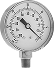
Bottom Connection | Bottom Connection with Rubber Cover | Center-Back Connection | Center-Back Connection (Panel Mount) |
| | | |
Bottom Connection | Bottom Connection with Rubber Cover | Center-Back Connection | Center-Back Connection (Panel Mount) |
Temp. Range, ° F | Bottom Connection | Bottom Connection with Rubber Cover | Center-Back Connection | Center-Back Connection (Panel Mount) | |||||||||||||
|---|---|---|---|---|---|---|---|---|---|---|---|---|---|---|---|---|---|
Dial Dia. | Pipe Size | Environment | Process | For Use With | Accuracy | Choose a Pressure Range | Each | Each | Each | For Panel Cutout Dia. | Each | ||||||
Any-Angle Mount | |||||||||||||||||
NPT Male | |||||||||||||||||
| 2" | 1/8 | -40 to 150 | -40 to 150 | Air Ethyl Alcohol Hydraulic Fluid Natural Gas Nitrogen Water | ±2% Midscale (Grade B) | 0 to 15 psi/0 to 100 kPa; 0 to 30 psi/0 to 200 kPa; 0 to 60 psi/0 to 400 kPa; 0 to 100 psi/0 to 700 kPa; 0 to 160 psi/0 to 1,100 kPa; 0 to 200 psi/0 to 1,400 kPa; 0 to 300 psi/0 to 2,000 kPa; 0 to 400 psi/0 to 2,800 kPa; 0 to 600 psi/0 to 4,000 kPa; 0 to 1,000 psi/0 to 7,000 kPa | 4000K744 | 000000 | 2201T53 | 000000 | 4000K745 | 000000 | 2 7/32" | 4000K746 | 000000 | ||
| 2" | 1/4 | -40 to 150 | -40 to 150 | Air Ethyl Alcohol Hydraulic Fluid Natural Gas Nitrogen Water | ±2% Midscale (Grade B) | 0 to 15 psi/0 to 100 kPa; 0 to 30 psi/0 to 200 kPa; 0 to 60 psi/0 to 400 kPa; 0 to 100 psi/0 to 700 kPa; 0 to 160 psi/0 to 1,100 kPa; 0 to 200 psi/0 to 1,400 kPa; 0 to 300 psi/0 to 2,000 kPa; 0 to 400 psi/0 to 2,800 kPa; 0 to 600 psi/0 to 4,000 kPa; 0 to 1,000 psi/0 to 7,000 kPa; 0 to 2,000 psi/0 to 14,000 kPa; 0 to 3,000 psi/0 to 20,000 kPa; 0 to 4,000 psi/0 to 28,000 kPa; 0 to 5,000 psi/0 to 35,000 kPa; 0 to 6,000 psi/0 to 40,000 kPa | 4000K721 | 00000 | 2201T55 | 00000 | 4000K791 | 00000 | 2 7/32" | 4000K728 | 00000 | ||
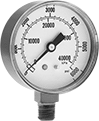
3-in-1 Pressure and Vacuum Gauges
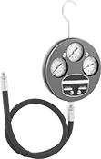 | |
Bottom Connection |
Left Gauge | Bottom Connection | |||||||||||||
|---|---|---|---|---|---|---|---|---|---|---|---|---|---|---|
Dial Dia. | Pipe Size | Pressure Range | Vacuum Range | Middle Gauge Pressure Range | Right Gauge Pressure Range | Environment Temp. Range, ° F | Process Temp. Range, ° F | Overall Dia. | For Use With | Accuracy | Each | |||
Steel Case with Steel Connection—Dual Scale (Centimeters of Mercury, Inches of Mercury, Kilograms per Square Centimeter, Pounds per Square Inch) | ||||||||||||||
NPTF Male | ||||||||||||||
| 2" | 1/8 | 0 psi to 150 psi, 0 kg/cm² to 10 kg/cm² | 0 in. Hg to 30 in. Hg, 0 cm Hg to 76 cm Hg | 0 psi to 5,000 psi; 0 kg/cm² to 350 kg/cm² | 0 psi to 600 psi, 0 kg/cm² to 42 kg/cm² | -40 to 120 | -40 to 190 | 6 7/16" | Air, Hydraulic Fluid | ±2% Midscale (Grade B) | 4054K64 | 0000000 | ||
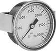
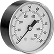
Gas Pressure Gauges
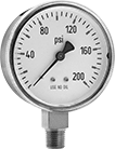 | |
Bottom Connection | Bottom Connection |
Temp. Range, ° F | Bottom Connection | |||||||||
|---|---|---|---|---|---|---|---|---|---|---|
Dial Dia. | Pipe Size | Environment | Process | For Use With | Accuracy | Choose a Pressure Range | Each | |||
Upright Mount | ||||||||||
NPT Male | ||||||||||
| 2" | 1/4 | -40 to 140 | -40 to 140 | Acetylene Air Carbon Dioxide Oxygen | ±2% Midscale (Grade B) | 0 to 30 psi, 0 to 60 psi, 0 to 100 psi, 0 to 200 psi, 0 to 400 psi, 0 to 600 psi, 0 to 1,000 psi, 0 to 2,000 psi, 0 to 3,000 psi, 0 to 4,000 psi | 32255K7 | 000000 | ||
Vibration-Resistant Drinking Water Pressure Gauges
 | |
Bottom Connection |
Temp. Range, ° F | Bottom Connection | ||||||||||||
|---|---|---|---|---|---|---|---|---|---|---|---|---|---|
Dial Dia. | Pipe Size | Environment | Process | Liquid Type | For Use With | Accuracy | Environment | Food Industry Std. | Choose a Pressure Range | Each | |||
Upright Mount | |||||||||||||
NPT Male | |||||||||||||
| 2" | 1/4 | -4 to 150 | -4 to 150 | Glycerin | Drinking Water | ±2.5% Full Scale (Not Rated) | Food and Beverage | NSF/ANSI 61 | 0 to 15 psi/0 to 100 kPa, 0 to 30 psi/0 to 210 kPa, 0 to 60 psi/0 to 400 kPa, 0 to 100 psi/0 to 700 kPa, 0 to 160 psi/0 to 1,100 kPa, 0 to 200 psi/0 to 1,400 kPa | 3427N3 | 000000 | ||
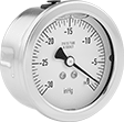
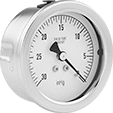
Vacuum Gauges
 |  |  | | | |
Bottom Connection | Center-Back Connection | Center-Back Connection (Panel Mount) | Bottom Connection | Center-Back Connection | Center-Back Connection (Panel Mount) |
Available Vacuum Ranges, in. Hg | Bottom Connection | Center-Back Connection | Center-Back Connection (Panel Mount) | |||||||||||||||
|---|---|---|---|---|---|---|---|---|---|---|---|---|---|---|---|---|---|---|
Dial Dia. | Pipe Size | Environment Temp. Range, ° F | Process Temp. Range, ° F | Case Color | Vacuum Range | Graduations | Pressure Numeric Increments | For Use With | Accuracy | Each | Each | For Panel Cutout Dia. | Each | |||||
NPT Male | ||||||||||||||||||
| 2" | 1/4 | -40 to 150 | -40 to 150 | Black | -30 to 0 | 0.5 | 5 | Air | ±2% Midscale (Grade B) | 4002K123 | 000000 | 4002K115 | 000000 | 2 7/32" | 4002K114 | 000000 | ||
NPT Male with Calibration Certificate Traceable to NIST | ||||||||||||||||||
| 2" | 1/4 | -40 to 150 | -40 to 150 | Black | -30 to 0 | 0.5 | 5 | Air | ±2% Midscale (Grade B) | 4002K136 | 00000 | 4002K127 | 00000 | — | ——— | 0 | ||
 |  |  | | | |
Bottom Connection | Center-Back Connection | Center-Back Connection (Panel Mount) | Bottom Connection | Center-Back Connection | Center-Back Connection (Panel Mount) |
Available Vacuum Ranges | Bottom Connection | Center-Back Connection | Center-Back Connection (Panel Mount) | |||||||||||||||
|---|---|---|---|---|---|---|---|---|---|---|---|---|---|---|---|---|---|---|
Dial Dia. | Pipe Size | Environment Temp. Range, ° F | Process Temp. Range, ° F | Case Color | Vacuum Range | Graduations | Pressure Numeric Increments | For Use With | Accuracy | Each | Each | For Panel Cutout Dia. | Each | |||||
NPT Male | ||||||||||||||||||
| 2" | 1/4 | -40 to 150 | -40 to 150 | Black | -30 in. Hg to 0 in. Hg -100 kPa to 0 kPa | 0.5 in. Hg 2 kPa | 5 in. Hg 10 kPa | Air | ±2% Midscale (Grade B) | 4002K14 | 000000 | 4002K34 | 000000 | 2 7/32" | 4002K24 | 000000 | ||
NPT Male with Calibration Certificate Traceable to NIST | ||||||||||||||||||
| 2" | 1/4 | -40 to 150 | -40 to 150 | Black | -30 in. Hg to 0 in. Hg -100 kPa to 0 kPa | 0.5 in. Hg 2 kPa | 5 in. Hg 10 kPa | Air | ±2% Midscale (Grade B) | 4002K142 | 00000 | 4002K167 | 00000 | — | ——— | 0 | ||
| | | |
Bottom Connection | Center-Back Connection | Bottom Connection | Center-Back Connection |
Available Vacuum Ranges, in. Hg | Bottom Connection | Center-Back Connection | |||||||||||||
|---|---|---|---|---|---|---|---|---|---|---|---|---|---|---|---|
Dial Dia. | Pipe Size | Environment Temp. Range, ° F | Process Temp. Range, ° F | Case Color | Vacuum Range | Graduations | Pressure Numeric Increments | For Use With | Accuracy | Each | Each | ||||
NPT Male | |||||||||||||||
| 2" | 1/8 | -40 to 140 | -40 to 140 | Black | -30 to 0 | 0.5 | 5 | Air | ±2% Midscale (Grade B) | 3935K52 | 000000 | 3935K62 | 000000 | ||
| | | |
Bottom Connection | Center-Back Connection | Bottom Connection | Center-Back Connection |
Available Vacuum Ranges | Bottom Connection | Center-Back Connection | |||||||||||||
|---|---|---|---|---|---|---|---|---|---|---|---|---|---|---|---|
Dial Dia. | Pipe Size | Environment Temp. Range, ° F | Process Temp. Range, ° F | Case Color | Vacuum Range | Graduations | Pressure Numeric Increments | For Use With | Accuracy | Each | Each | ||||
NPT Male | |||||||||||||||
| 2" | 1/8 | -40 to 140 | -40 to 140 | Black | -30 in. Hg to 0 in. Hg -100 kPa to 0 kPa | 0.5 in. Hg 2 kPa | 5 in. Hg 10 kPa | Air | ±2% Midscale (Grade B) | 3935K35 | 000000 | 3935K36 | 000000 | ||
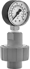
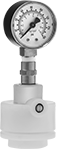
Low-Pressure Gauges for Chemicals
 |  |
PVC Guard | Bottom Connection (PVC, CPVC, and Polypropylene Guards) |
Temp. Range, ° F | Bottom Connection | ||||||||||||
|---|---|---|---|---|---|---|---|---|---|---|---|---|---|
Dial Dia. | Pipe Size | Case Color | Environment | Process | For Use With | Accuracy | Guard Material | Guard Color | Choose a Pressure Range | Each | |||
NPT Female | |||||||||||||
| 2" | 1/4 | Black | 40 to 140 | 40 to 140 | Boric Acid Carbon Dioxide Hydraulic Fluid Salt Water Sodium Hypochlorite (Bleach) Water | ±2% Midscale (Grade B) | PVC | Gray | 0 to 30 psi/0 to 2.1 kg per cm², 0 to 60 psi/0 to 4.2 kg per cm², 0 to 150 psi/0 to 11.2 kg per cm² | 4091K23 | 0000000 | ||
| 2" | 1/2 | Black | 40 to 140 | 40 to 140 | Boric Acid Carbon Dioxide Hydraulic Fluid Salt Water Sodium Hypochlorite (Bleach) Water | ±2% Midscale (Grade B) | PVC | Gray | 0 to 30 psi/0 to 2.1 kg per cm², 0 to 60 psi/0 to 4.2 kg per cm², 0 to 150 psi/0 to 11.2 kg per cm² | 4091K24 | 000000 | ||
 | |
CPVC Guard | Bottom Connection (PVC, CPVC, and Polypropylene Guards) |
Temp. Range, ° F | Bottom Connection | ||||||||||||
|---|---|---|---|---|---|---|---|---|---|---|---|---|---|
Dial Dia. | Pipe Size | Case Color | Environment | Process | For Use With | Accuracy | Guard Material | Guard Color | Choose a Pressure Range | Each | |||
NPT Female | |||||||||||||
| 2" | 1/4 | Black | 40 to 190 | 40 to 190 | Boric Acid Carbon Dioxide Hydraulic Fluid Salt Water Sodium Hypochlorite (Bleach) Water | ±2% Midscale (Grade B) | CPVC | Gray | 0 to 30 psi/0 to 2.1 kg per cm², 0 to 60 psi/0 to 4.2 kg per cm², 0 to 150 psi/0 to 11.2 kg per cm² | 4147K41 | 0000000 | ||
| 2" | 1/2 | Black | 40 to 190 | 40 to 190 | Boric Acid Carbon Dioxide Hydraulic Fluid Salt Water Sodium Hypochlorite (Bleach) Water | ±2% Midscale (Grade B) | CPVC | Gray | 0 to 30 psi/0 to 2.1 kg per cm², 0 to 60 psi/0 to 4.2 kg per cm², 0 to 150 psi/0 to 11.2 kg per cm² | 4147K42 | 000000 | ||
 | |
Polypropylene Guard | Bottom Connection (PVC, CPVC, and Polypropylene Guards) |
Temp. Range, ° F | Bottom Connection | ||||||||||||
|---|---|---|---|---|---|---|---|---|---|---|---|---|---|
Dial Dia. | Pipe Size | Case Color | Environment | Process | For Use With | Accuracy | Guard Material | Guard Color | Choose a Pressure Range | Each | |||
NPT Female | |||||||||||||
| 2" | 1/4 | Black | 40 to 240 | 40 to 240 | Boric Acid Carbon Dioxide Hydraulic Fluid Salt Water Water | ±2% Midscale (Grade B) | Polypropylene | White | 0 to 30 psi/0 to 2.1 kg per cm², 0 to 60 psi/0 to 4.2 kg per cm², 0 to 150 psi/0 to 11.2 kg per cm² | 4134K23 | 0000000 | ||
Drinking Water Pressure Gauges
 |  | | |
Bottom Connection | Center-Back Connection | Bottom Connection | Center-Back Connection |
Temp. Range, ° F | Bottom Connection | Center-Back Connection | |||||||||||||
|---|---|---|---|---|---|---|---|---|---|---|---|---|---|---|---|
Dial Dia. | Pipe Size | Case Color | Environment | Process | For Use With | Accuracy | Environment | Food Industry Std. | Choose a Pressure Range | Each | Each | ||||
Upright Mount | |||||||||||||||
NPT Male | |||||||||||||||
| 2" | 1/4 | Black | -40 to 150 | -40 to 150 | Drinking Water | ±2% Midscale (Grade B) | Food and Beverage | NSF/ANSI 61 | 0 to 15 psi/0 to 100 kPa; 0 to 30 psi/0 to 200 kPa; 0 to 60 psi/0 to 400 kPa; 0 to 100 psi/0 to 700 kPa; 0 to 160 psi/0 to 1,100 kPa; 0 to 200 psi/0 to 1,400 kPa | 3515N1 | 000000 | 3515N6 | 000000 | ||
Vibration- and Corrosion-Resistant Vacuum Gauges
 | 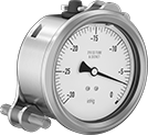 | | |
Center-Back Connection | Center-Back Connection (Panel Mount) | Center-Back Connection | Center-Back Connection (Panel Mount) |
Available Vacuum Ranges, in. Hg | Center-Back Connection | Center-Back Connection (Panel Mount) | ||||||||||||||
|---|---|---|---|---|---|---|---|---|---|---|---|---|---|---|---|---|
Dial Dia. | Pipe Size | Environment Temp. Range, ° F | Process Temp. Range, ° F | Liquid Type | Vacuum Range | Graduations | Pressure Numeric Increments | For Use With | Accuracy | Each | For Panel Cutout Dia. | Each | ||||
NPT Male | ||||||||||||||||
| 2" | 1/8 | 0 to 140 | 0 to 210 | Glycerin | -30 to 0 | 0.5 | 5 | Air | ±1% Midscale (Grade A) | 38545K411 | 0000000 | 2 5/64" | 38545K412 | 0000000 | ||
Corrosion-Resistant Vacuum Gauges
 |  | | |
Bottom Connection | Center-Back Connection | Bottom Connection | Center-Back Connection |
Available Vacuum Ranges, in. Hg | Bottom Connection | Center-Back Connection | ||||||||||||
|---|---|---|---|---|---|---|---|---|---|---|---|---|---|---|
Dial Dia. | Pipe Size | Environment Temp. Range, ° F | Process Temp. Range, ° F | Vacuum Range | Graduations | Pressure Numeric Increments | For Use With | Accuracy | Each | Each | ||||
NPT Male | ||||||||||||||
| 2" | 1/8 | -40 to 200 | -40 to 250 | -30 to 0 | 0.5 | 5 | Air | ±2% Midscale (Grade B) | 3961K914 | 0000000 | 3961K913 | 0000000 | ||
| 2" | 1/4 | -40 to 200 | -40 to 250 | -30 to 0 | 0.5 | 5 | Air | ±2% Midscale (Grade B) | 3961K916 | 000000 | 3961K915 | 000000 | ||
Tire Gauges with Dial
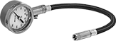 | 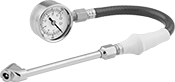 | 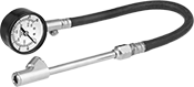 |
Style C | Style D | Style E |
Hose | |||||||||||||||
|---|---|---|---|---|---|---|---|---|---|---|---|---|---|---|---|
Style | Head Type | No. of Heads | Pressure Range | Pressure Numeric Increments, psi | Accuracy | Overall Lg. | Dial Dia. | Material | Case Material | Lg. | Material | Features | Each | ||
| C | Straight | 1 | 0 psi to 160 psi; 0 kPa to 1,100 kPa | 5 | ±3% | 14" | 2" | Chrome-Plated Brass | Rubber | 5" | Rubber | Rubber Sleeve | 6643A101 | 000000 | |
| C | Straight | 1 | 5 psi to 160 psi | 1 | ±3% | 16 1/2" | 2" | Chrome-Plated Steel | Painted Steel | 11" | Rubber | — | 6646A22 | 00000 | |
| D | Angled | 2 | 0 psi to 60 psi; 0 kPa to 400 kPa | 1 | ±3% | 20" | 2" | Chrome-Plated Brass, Chrome-Plated Zinc Alloy | — | 10" | Rubber | Rubber Sleeve | 6643A311 | 00000 | |
| D | Angled | 2 | 0 psi to 160 psi; 0 kPa to 1,100 kPa | 1 | ±3% | 20" | 2" | Chrome-Plated Brass, Chrome-Plated Zinc Alloy | — | 10" | Rubber | Rubber Sleeve | 6643A22 | 00000 | |
| D | Angled | 2 | 0 psi to 300 psi; 0 kPa to 2,060 kPa | 5 | ±3% | 20" | 2" | Chrome-Plated Brass, Chrome-Plated Zinc Alloy | — | 10" | Rubber | Rubber Sleeve | 6643A23 | 00000 | |
| E | Angled, Straight | 2 | 0 psi to 160 psi; 0 kPa to 1,100 kPa | 5 | ±3% | 23" | 2" | Chrome-Plated Brass, Chrome-Plated Zinc Alloy | — | 12" | Rubber | — | 6643A312 | 00000 | |
Pressure and Vacuum Gauges
 |  |  | | | |
Dual Scale Bottom Connection | Dual Scale, Center-Back Connection | Dual Scale, Center-Back Connection (Panel Mount) | Bottom Connection | Center-Back Connection | Center-Back Connection (Panel Mount) |
Bottom Connection | Center-Back Connection | Center-Back Connection (Panel Mount) | |||||||||||||||||
|---|---|---|---|---|---|---|---|---|---|---|---|---|---|---|---|---|---|---|---|
Dial Dia. | Pipe Size | Environment Temp. Range, ° F | Process Temp. Range, ° F | Lens Material | Pressure | Vacuum | Graduations | Pressure Numeric Increments | For Use With | Accuracy | Each | Each | For Panel Cutout Dia. | Each | |||||
Steel Case with Brass Connection—Dual Scale (Inches of Mercury, Kilopascals, Pounds per Square Inch) | |||||||||||||||||||
NPT Male | |||||||||||||||||||
| 2" | 1/4 | -40 to 150 | -40 to 150 | Polycarbonate | 0 psi to 15 psi; 0 kPa to 100 kPa | -100 in. Hg to 30 in. Hg, 0 in. Hg to 30 in. Hg, -100 kPa to 0 kPa | 1 in. Hg, 0.5 psi, 5 kPa | 5 in. Hg, 5 psi, 20 kPa | Air | ±2% Midscale (Grade B) | 4004K41 | 000000 | 4004K712 | 000000 | 2 7/32" | 4004K521 | 000000 | ||
| 2" | 1/4 | -40 to 150 | -40 to 150 | Polycarbonate | 0 psi to 30 psi; 0 kPa to 200 kPa | -100 in. Hg to 30 in. Hg, 0 in. Hg to 30 in. Hg, -100 kPa to 0 kPa | 1 in. Hg, 1 psi, 5 kPa | 5 in. Hg, 5 psi, 50 kPa | Air | ±2% Midscale (Grade B) | 4004K42 | 00000 | 4004K713 | 00000 | 2 7/32" | 4004K522 | 00000 | ||
| 2" | 1/4 | -40 to 150 | -40 to 150 | Polycarbonate | 0 psi to 75 psi; 0 kPa to 500 kPa | -100 in. Hg to 30 in. Hg, 0 in. Hg to 30 in. Hg, -100 kPa to 0 kPa | 2 in. Hg, 5 psi, 20 kPa | 10 in. Hg, 10 psi, 100 kPa | Air | ±2% Midscale (Grade B) | 4004K43 | 00000 | 4004K715 | 00000 | 2 7/32" | 4004K523 | 00000 | ||
| 2" | 1/4 | -40 to 150 | -40 to 150 | Polycarbonate | 0 psi to 100 psi; 0 kPa to 700 kPa | -100 in. Hg to 30 in. Hg, 0 in. Hg to 30 in. Hg, -100 kPa to 0 kPa | 2 psi, 5 in. Hg, 20 kPa | 15 in. Hg, 10 psi, 100 kPa | Air | ±2% Midscale (Grade B) | 4004K44 | 00000 | 4004K716 | 00000 | 2 7/32" | 4004K524 | 00000 | ||
| 2" | 1/4 | -40 to 150 | -40 to 150 | Polycarbonate | 0 psi to 160 psi; 0 kPa to 1,100 kPa | -100 in. Hg to 30 in. Hg, 0 in. Hg to 30 in. Hg, -100 kPa to 0 kPa | 2 psi, 5 in. Hg, 20 kPa | 30 in. Hg, 20 psi, 200 kPa | Air | ±2% Midscale (Grade B) | 4004K45 | 00000 | 4004K717 | 00000 | 2 7/32" | 4004K525 | 00000 | ||
| 2" | 1/4 | -40 to 150 | -40 to 150 | Polycarbonate | 0 psi to 200 psi; 0 kPa to 1,400 kPa | -100 in. Hg to 30 in. Hg, 0 in. Hg to 30 in. Hg, -100 kPa to 0 kPa | 2 psi, 5 in. Hg, 50 kPa | 30 in. Hg, 20 psi, 200 kPa | Air | ±2% Midscale (Grade B) | 4004K46 | 00000 | 4004K718 | 00000 | 2 7/32" | 4004K526 | 00000 | ||
| 2" | 1/4 | -40 to 150 | -40 to 150 | Polycarbonate | 0 psi to 300 psi; 0 kPa to 2,100 kPa | -100 in. Hg to 30 in. Hg, 0 in. Hg to 30 in. Hg, -100 kPa to 0 kPa | 15 in. Hg, 10 psi, 50 kPa | 30 in. Hg, 50 psi, 300 kPa | Air | ±2% Midscale (Grade B) | 4004K47 | 00000 | 4004K719 | 00000 | 2 7/32" | 4004K527 | 00000 | ||
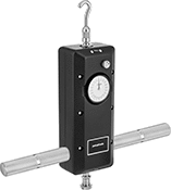
Tension and Compression Force Gauges
Gauges | Handles | ||||||||||||
|---|---|---|---|---|---|---|---|---|---|---|---|---|---|
Wt. Cap., lb. | Accuracy | Wt. Measuring Increments, lb. | Ht. | Wd. | Dp. | Dial Dia. | Shaft Thread Size | Includes | Each | Each | |||
| 2 | ±0.006 lb. | 0.01 | 9 1/8" | 2 3/4" | 1 7/8" | 2" | 10-32 | Chisel Tip Attachment, Cone Tip Attachment, Flat Tip Attachment, Large Hook Attachment, Notched Tip Attachment, Small Hook Attachment, Y-Hook Attachment, 3-1/4" Extension Rod | 17435T31 | 0000000 | 17435T38 | 0000000 | |
| 5 | ±0.015 lb. | 0.025 | 9 1/8" | 2 3/4" | 1 7/8" | 2" | 10-32 | Chisel Tip Attachment, Cone Tip Attachment, Flat Tip Attachment, Large Hook Attachment, Notched Tip Attachment, Small Hook Attachment, Y-Hook Attachment, 3-1/4" Extension Rod | 17435T32 | 000000 | 17435T38 | 000000 | |
| 10 | ±0.03 lb. | 0.05 | 9 1/8" | 2 3/4" | 1 7/8" | 2" | 10-32 | Chisel Tip Attachment, Cone Tip Attachment, Flat Tip Attachment, Large Hook Attachment, Notched Tip Attachment, Small Hook Attachment, Y-Hook Attachment, 3-1/4" Extension Rod | 17435T33 | 000000 | 17435T38 | 000000 | |
| 20 | ±0.06 lb. | 0.1 | 9 1/8" | 2 3/4" | 1 7/8" | 2" | 10-32 | Chisel Tip Attachment, Cone Tip Attachment, Flat Tip Attachment, Large Hook Attachment, Notched Tip Attachment, Small Hook Attachment, Y-Hook Attachment, 3-1/4" Extension Rod | 17435T34 | 000000 | 17435T38 | 000000 | |
| 30 | ±0.09 lb. | 0.2 | 9 1/8" | 2 3/4" | 1 7/8" | 2" | 10-32 | Chisel Tip Attachment, Cone Tip Attachment, Flat Tip Attachment, Large Hook Attachment, Notched Tip Attachment, Small Hook Attachment, Y-Hook Attachment, 3-1/4" Extension Rod | 17435T35 | 000000 | 17435T38 | 000000 | |
| 50 | ±0.15 lb. | 1/4 | 9 1/8" | 2 3/4" | 1 7/8" | 2" | 10-32 | Chisel Tip Attachment, Cone Tip Attachment, Flat Tip Attachment, Large Hook Attachment, Notched Tip Attachment, Small Hook Attachment, Y-Hook Attachment, 3-1/4" Extension Rod | 17435T36 | 000000 | 17435T38 | 000000 | |
| 100 | ±0.3 lb. | 1/2 | 9 1/8" | 2 3/4" | 1 7/8" | 2" | 10-32 | Chisel Tip Attachment, Cone Tip Attachment, Flat Tip Attachment, Large Hook Attachment, Notched Tip Attachment, Small Hook Attachment, Y-Hook Attachment, 3-1/4" Extension Rod | 17435T37 | 000000 | 17435T38 | 000000 | |
 |  | 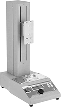 |
Lever Handle | Wheel Handle | Button Operation |
Overall | ||||||||||||
|---|---|---|---|---|---|---|---|---|---|---|---|---|
Wt. Cap., lb. | Measures | Ht. | Wd. | Dp. | Column Material | Base Material | Mounting Plate Material | Shaft Thread Size | Each | |||
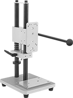
Manual Operation with Lever Handle | ||||||||||||
| 220 | Compression | 17 51/64" | 7 7/8" | 9 27/32" | Steel | Aluminum | Nickel-Plated Steel | — | 17435T63 | 0000000 | ||
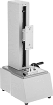
Manual Operation with Wheel Handle | ||||||||||||
| 220 | Compression, Tension | 28 3/4" | 12" | 10 13/16" | Steel | Steel | Aluminum | M8, M6 | 17435T111 | 00000000 | ||
Motor Operation with Button | ||||||||||||
| 110 | Compression, Tension | 22 1/4" | 8 3/4" | 15" | Steel | Steel | Aluminum | M6 | 17435T109 | 00000000 | ||
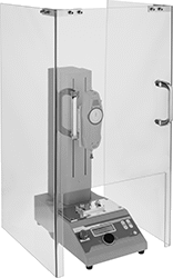 |
Gauge and Stand Sold Separately |
Ht. | Wd. | Lg. | Thk. | Material | Each | ||
|---|---|---|---|---|---|---|---|
| 31 1/2" | 16 1/2" | 15 3/4" | 0.25" | Polycarbonate | 17435T108 | 0000000 |
 |
Wt. Cap., lb. | Accuracy | Wt. Measuring Increments, lb. | Ht. | Wd. | Dp. | Dial Dia. | Shaft Thread Size | Includes | Each | ||
|---|---|---|---|---|---|---|---|---|---|---|---|
| 200 | ±0.8 lb. | 1 | 9 1/2" | 3 3/4" | 2 1/2" | 2" | M10 | Chisel Tip Attachment, Cone Tip Attachment, Flat Tip Attachment, Notched Tip Attachment, Small Hook Attachment, Handles, Mounting Bolts, 4 1/4" Extension Rod | 17435T101 | 000000000 | |
| 300 | ±1.2 lb. | 2 | 9 1/2" | 3 3/4" | 2 1/2" | 2" | M10 | Chisel Tip Attachment, Cone Tip Attachment, Flat Tip Attachment, Notched Tip Attachment, Small Hook Attachment, Handles, Mounting Bolts, 4 1/4" Extension Rod | 17435T102 | 00000000 | |
| 400 | ±1.6 lb. | 2 | 9 1/2" | 3 3/4" | 2 1/2" | 2" | M10 | Chisel Tip Attachment, Cone Tip Attachment, Flat Tip Attachment, Notched Tip Attachment, Small Hook Attachment, Handles, Mounting Bolts, 4 1/4" Extension Rod | 17435T103 | 00000000 | |
| 500 | ±2 lb. | 2 1/2 | 9 1/2" | 3 3/4" | 2 1/2" | 2" | M10 | Chisel Tip Attachment, Cone Tip Attachment, Flat Tip Attachment, Notched Tip Attachment, Small Hook Attachment, Handles, Mounting Bolts, 4 1/4" Extension Rod | 17435T104 | 00000000 |
Gauges | Handles | ||||||||||||
|---|---|---|---|---|---|---|---|---|---|---|---|---|---|
Max. Wt. Cap., kg | Accuracy | Wt. Measuring Increments, g | Ht. | Wd. | Dp. | Dial Dia. | Shaft Thread Size | Includes | Each | Each | |||
| 50 | ±150 g | 250 | 9 1/8" | 2 3/4" | 1 7/8" | 2" | 10-32 | Chisel Tip Attachment, Cone Tip Attachment, Flat Tip Attachment, Large Hook Attachment, Notched Tip Attachment, Small Hook Attachment, Y-Hook Attachment, 3-1/4" Extension Rod | 17435T45 | 0000000 | 17435T38 | 0000000 | |
| | |
Lever Handle | Wheel Handle | Button Operation |
Overall | ||||||||||||
|---|---|---|---|---|---|---|---|---|---|---|---|---|
Wt. Cap., lb. | Measures | Ht. | Wd. | Dp. | Column Material | Base Material | Mounting Plate Material | Shaft Thread Size | Each | |||
Manual Operation with Lever Handle | ||||||||||||
| 220 | Compression | 17 51/64" | 7 7/8" | 9 27/32" | Steel | Aluminum | Nickel-Plated Steel | — | 17435T63 | 0000000 | ||
Manual Operation with Wheel Handle | ||||||||||||
| 220 | Compression, Tension | 28 3/4" | 12" | 10 13/16" | Steel | Steel | Aluminum | M8, M6 | 17435T111 | 00000000 | ||
Motor Operation with Button | ||||||||||||
| 110 | Compression, Tension | 22 1/4" | 8 3/4" | 15" | Steel | Steel | Aluminum | M6 | 17435T109 | 00000000 | ||
|
Gauge and Stand Sold Separately |
Ht. | Wd. | Lg. | Thk. | Material | Each | ||
|---|---|---|---|---|---|---|---|
| 31 1/2" | 16 1/2" | 15 3/4" | 0.25" | Polycarbonate | 17435T108 | 0000000 |
Gauges | Handles | ||||||||||||
|---|---|---|---|---|---|---|---|---|---|---|---|---|---|
Force Cap., N | Accuracy | Force Measuring Increments, N | Ht. | Wd. | Dp. | Dial Dia. | Shaft Thread Size | Includes | Each | Each | |||
| 10 | ±0.03 N | 0.05 | 9 1/8" | 2 3/4" | 1 7/8" | 2" | 10-32 | Chisel Tip Attachment, Cone Tip Attachment, Flat Tip Attachment, Large Hook Attachment, Notched Tip Attachment, Small Hook Attachment, Y-Hook Attachment, 3 1/4" Extension Rod | 17435T106 | 0000000 | 17435T38 | 0000000 | |
| 50 | ±0.15 N | 0.25 | 9 1/8" | 2 3/4" | 1 7/8" | 2" | 10-32 | Chisel Tip Attachment, Cone Tip Attachment, Flat Tip Attachment, Large Hook Attachment, Notched Tip Attachment, Small Hook Attachment, Y-Hook Attachment, 3 1/4" Extension Rod | 17435T105 | 000000 | 17435T38 | 000000 | |
| 100 | ±0.3 N | 0.5 | 9 1/8" | 2 3/4" | 1 7/8" | 2" | 10-32 | Chisel Tip Attachment, Cone Tip Attachment, Flat Tip Attachment, Large Hook Attachment, Notched Tip Attachment, Small Hook Attachment, Y-Hook Attachment, 3 1/4" Extension Rod | 17435T73 | 000000 | 17435T38 | 000000 | |
| 200 | ±0.6 N | 1 | 9 1/8" | 2 3/4" | 1 7/8" | 2" | 10-32 | Chisel Tip Attachment, Cone Tip Attachment, Flat Tip Attachment, Large Hook Attachment, Notched Tip Attachment, Small Hook Attachment, Y-Hook Attachment, 3 1/4" Extension Rod | 17435T74 | 000000 | 17435T38 | 000000 | |
| 500 | ±1.5 N | 2.5 | 9 1/8" | 2 3/4" | 1 7/8" | 2" | 10-32 | Chisel Tip Attachment, Cone Tip Attachment, Flat Tip Attachment, Large Hook Attachment, Notched Tip Attachment, Small Hook Attachment, Y-Hook Attachment, 3 1/4" Extension Rod | 17435T75 | 000000 | 17435T38 | 000000 | |
| | |
Lever Handle | Wheel Handle | Button Operation |
Overall | ||||||||||||
|---|---|---|---|---|---|---|---|---|---|---|---|---|
Wt. Cap., lb. | Measures | Ht. | Wd. | Dp. | Column Material | Base Material | Mounting Plate Material | Shaft Thread Size | Each | |||
Manual Operation with Lever Handle | ||||||||||||
| 220 | Compression | 17 51/64" | 7 7/8" | 9 27/32" | Steel | Aluminum | Nickel-Plated Steel | — | 17435T63 | 0000000 | ||
Manual Operation with Wheel Handle | ||||||||||||
| 220 | Compression, Tension | 28 3/4" | 12" | 10 13/16" | Steel | Steel | Aluminum | M8, M6 | 17435T111 | 00000000 | ||
Motor Operation with Button | ||||||||||||
| 110 | Compression, Tension | 22 1/4" | 8 3/4" | 15" | Steel | Steel | Aluminum | M6 | 17435T109 | 00000000 | ||
|
Gauge and Stand Sold Separately |
Ht. | Wd. | Lg. | Thk. | Material | Each | ||
|---|---|---|---|---|---|---|---|
| 31 1/2" | 16 1/2" | 15 3/4" | 0.25" | Polycarbonate | 17435T108 | 0000000 |
