


Filter by
System of Measurement
Maximum Pressure
For Use With
Connection Location

Thread Type
Pressure Resolution
Measurement Unit
Connection Material
Dial Type

Scale Type

Fitting Connection
DFARS Specialty Metals

About Pressure Gauges
Find a gauge with the right connection material and dial type—many with traceable calibration certificates.
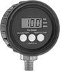
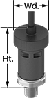
Digital-Display High-Accuracy Pressure Gauges
ABS Case with 316 Stainless Steel Connection—(Pounds per Square Inch, Bar, Megapascals)
 | |
Bottom Connection |
Temp. Range, ° F | Batteries | Bottom Connection | ||||||||||||
|---|---|---|---|---|---|---|---|---|---|---|---|---|---|---|
Dial Dia. | Pipe Size | Case Color | Environment | Process | Included | Size | Features | For Use With | Accuracy | Pressure Range | Each | |||
Any-Angle Mount | ||||||||||||||
NPT Male | ||||||||||||||
| 2 1/2" | 1/4 | Black | 0 to 185 | 15 to 140 | Yes | 9V | 3-min. Automatic Shut-Off Maximum Reading Recall | Air Diesel Fuel Gasoline Hydraulic Fluid Natural Gas Water | ±1% Full Scale (Not Rated) | 0 to 500 psi/0 to 34.4 bar/0 to 3.4 MPa | 3834K111 | 0000000 | ||
NPT Male with Calibration Certificate Traceable to NIST | ||||||||||||||
| 2 1/2" | 1/4 | Black | 0 to 185 | 15 to 140 | Yes | 9V | 3-min. Automatic Shut-Off Maximum Reading Recall | Air Diesel Fuel Gasoline Hydraulic Fluid Natural Gas Water | ±1% Full Scale (Not Rated) | 0 to 500 psi/0 to 34.4 bar/0 to 3.4 MPa | 3834K311 | 000000 | ||
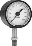
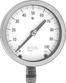
Miniature Pressure Gauges
Nickel-Plated Brass Case with Nickel-Plated Brass Connection—Single Scale (Pounds per Square Inch)
 |  |
Center-Back Connection |
Temp. Range, ° F | Center-Back Connection | |||||||||
|---|---|---|---|---|---|---|---|---|---|---|
Dial Dia. | Pipe Size | Environment | Process | For Use With | Accuracy | Pressure Range | Each | |||
Any-Angle Mount | ||||||||||
NPT Male | ||||||||||
| 1" | 1/8 | -50 to 160 | -50 to 160 | Air Hydraulic Fluid Natural Gas Water | ±5% Full Scale (Grade D) | 0 to 500 psi | 9767T21 | 000000 | ||
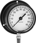
Extreme-Temperature Pressure Gauges
Aluminum Case with 316 Stainless Steel Connection—Single Scale (Pounds per Square Inch)
 |  | ||
Bottom Connection | Bottom Connection (Flange Mount) | Bottom Connection | Bottom Connection (Flange Mount) |
Bottom Connection | Bottom Connection (Flange Mount) | ||||||||||||||||||
|---|---|---|---|---|---|---|---|---|---|---|---|---|---|---|---|---|---|---|---|
Environment Temp. Range, ° F | Process Temp. Range, ° F | Flange | Bolt | ||||||||||||||||
Dial Dia. | Pipe Size | Min. | Max. | Min. | Max. | For Use With | Pressure Range | Each | Location | OD | Mounting Fasteners Included | Circle Dia. | Hole Dia. | No. of Holes | Each | ||||
Upright Mount | |||||||||||||||||||
NPT Male | |||||||||||||||||||
| 2 1/2" | 1/4 | -65 | 400 | -65 | 600 | Air Diesel Fuel Gasoline Hydraulic Fluid Natural Gas Water | 0 to 500 psi | 9891T23 | 0000000 | — | — | — | — | — | — | ——— | 0 | ||
| 3 1/2" | 1/4 | -65 | 400 | -65 | 600 | Air Diesel Fuel Gasoline Hydraulic Fluid Natural Gas Water | 0 to 500 psi | ——— | 0 | Back | 4 3/4" | No | 4 1/4" | 7/32" | 3 | 9891T24 | 0000000 | ||
Nylon Case with 316 Stainless Steel Connection—Single Scale (Pounds per Square Inch)
| |
Bottom Connection (Flange Mount) | Bottom Connection (Flange Mount) |
Bottom Connection (Flange Mount) | |||||||||||||||
|---|---|---|---|---|---|---|---|---|---|---|---|---|---|---|---|
Environment Temp. Range, ° F | Process Temp. Range, ° F | Mounting | |||||||||||||
Dial Dia. | Pipe Size | Min. | Max. | Min. | Max. | Case Color | For Use With | Pressure Range | Fasteners Included | Hole Dia. | No. of Holes | Each | |||
Upright Mount | |||||||||||||||
NPT Male | |||||||||||||||
| 4 1/2" | 1/2 | -65 | 400 | -65 | 600 | Yellow | Air Diesel Fuel Gasoline Hydraulic Fluid Natural Gas Water | 0 to 500 psi | No | 7/32" | 3 | 9891T25 | 0000000 | ||
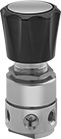
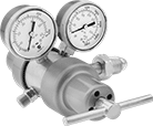
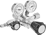
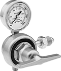
Panel-Mount Ultra-High-Pressure-Regulating Valves for Air and Inert Gas
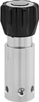 |
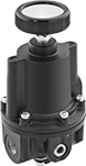
These valves are rated for inlet pressures up to 6,000 psi. They automatically reduce a high, variable inlet pressure to a lower, stable outlet pressure. Adjust the outlet pressure within the range. Threads below the adjustment knob and an included mounting bracket let you install these valves in instrument panels. They have two gauge ports. An internal strainer traps debris.
Inlet | Outlet | Gauge Port | |||||||||||||||||
|---|---|---|---|---|---|---|---|---|---|---|---|---|---|---|---|---|---|---|---|
Pipe Size | Location | Max. Pressure, psi | Pipe Size | Location | Pressure Adjustment Method | Pressure Gauge Included | Pipe Size | Location | Connection | End-to-End Lg. | Panel Cutout Dia. | For Use With | Temp. Range, ° F | Specs. Met | Outlet Pressure, psi | Each | |||
NPT Female | |||||||||||||||||||
Brass Body—Polyimide Seal with Internal Strainer | |||||||||||||||||||
| 1/4 | Side | 6,000 | 1/4 | Side | Knob | No | 1/4 | Side | NPT Female | 2 1/8" | 2 1/4" | Air, Nitrogen, Argon, Helium | -40 to 165 | ASME B31.3 | 0 to 500 | 3950T21 | 000000000 | ||
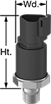
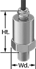
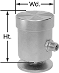
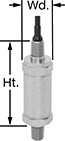
High-Accuracy Pressure Transmitters
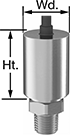 |
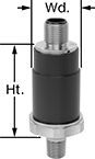
At least four times as accurate as standard pressure transmitters, these transmitters are ideal for use in laboratories and analytical testing applications. All come with a calibration certificate traceable to NIST that states they’ve passed a test for accuracy. Also known as transducers, pressure transmitters convert pressure to an electrical signal that can be interpreted by receiving devices, such as remote displays, programmable logic controllers, and motor speed controls to monitor pressure or control equipment. As pressure increases, the output signal from the transmitter will increase. For your receiving device to interpret the signal from the transmitter, you will need to calibrate it for the transmitter's pressure range and output signal. Transmitters will only provide accurate readings within the rated pressure range.
These transmitters connect using two wires to send a 4-20mA output current. The same wire is used to send a signal to the receiver and to power the transmitter. Current doesn’t lose signal over long distances and isn’t affected by electrical interference from other devices.
All transmitters are CE marked, meaning they meet European safety standards. NEMA 4X rated transmitters are for use in washdown and corrosive environments. IP67 rated transmitters are protected from temporary submersion during washdowns.
Transmitters with Calibration Certificate Traceable to NIST | ||||||||||||||||
|---|---|---|---|---|---|---|---|---|---|---|---|---|---|---|---|---|
Pressure Range, psi | Max. Continuous Pressure, psi | Max. Short-Term Pressure, psi | Input Voltage, V DC | Pipe Size | Ht. | Wd. | Temp. Range, ° F | Enclosure Rating | For Use With | Pipe Connection | Housing Material | Connection Material | Each | |||
4 mA to 20 mA Output Signal—Wire Lead Connection | ||||||||||||||||
±0.25% Accuracy | ||||||||||||||||
| 0 to 250 | 250 | 500 | 9 to 30 | 1/4 | 2 1/8" | 1" | -40 to 255 | IP67, NEMA 4X | Air Argon Diesel Fuel Gasoline Hydraulic Fluid Nitrogen Water | NPT Male | 304 Stainless Steel | 17-4 PH Stainless Steel | 3920N15 | 0000000 | ||
| 0 to 500 | 500 | 1,000 | 9 to 30 | 1/4 | 2 1/8" | 1" | -40 to 255 | IP67, NEMA 4X | Air Argon Diesel Fuel Gasoline Hydraulic Fluid Nitrogen Water | NPT Male | 304 Stainless Steel | 17-4 PH Stainless Steel | 3920N16 | 000000 | ||
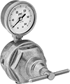
Panel-Mount High-Pressure-Regulating Valves for Air and Inert Gas
 |
Withstand inlet pressures up to 3,500 psi. These valves automatically reduce a high, variable inlet pressure to a lower, stable outlet pressure. Adjust the outlet pressure within the range. Valves have threads below the adjustment knob and come with a panel-mount nut. All have two gauge ports. An internal strainer traps debris.
Inlet | Outlet | Gauge Port | |||||||||||||||||
|---|---|---|---|---|---|---|---|---|---|---|---|---|---|---|---|---|---|---|---|
Pipe Size | Location | Max. Pressure, psi | Pipe Size | Location | Pressure Adjustment Method | Pressure Gauge Included | Pipe Size | Location | Connection | End-to-End Lg. | Panel Cutout Dia. | For Use With | Temp. Range, ° F | Specs. Met | Outlet Pressure, psi | Each | |||
NPT Female | |||||||||||||||||||
Brass Body—316 Stainless Steel Diaphragm and PTFE Seal with Internal Strainer | |||||||||||||||||||
| 1/4 | Side | 3,500 | 1/4 | Side | Knob | No | 1/4 | Side | NPT Female | 2" | 1 3/8" | Air, Nitrogen, Argon, Helium | -40 to 165 | ASME B31.3 | 0 to 500 | 3811T11 | 0000000 | ||
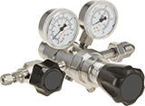
Tank-Mount Pressure-Regulating Valves for Moisture Removal
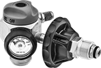 |
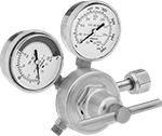
Designed for nitrogen gas purging in air conditioning, refrigeration, and plumbing systems, these valves automatically reduce a high inlet pressure to a lower, stable outlet pressure. They have Compressed Gas Association (CGA) numbered inlet fittings for secure connections to compressed gas tanks. Choose a valve with the same CGA number as your tank and other system components. Valves have 45° flared tube outlet fittings for a tight seal on metal tubing. They come with a gauge to monitor inlet pressure from the tank. They are single stage and reduce pressure in one step, which causes the outlet pressure to fluctuate slightly as you empty the tank.
Choose a valve with a maximum outlet pressure that’s approximately twice your application’s normal operating pressure. Your operating pressure should never exceed 75% of the valve’s maximum outlet pressure.
Inlet | Outlet | |||||||||||||||
|---|---|---|---|---|---|---|---|---|---|---|---|---|---|---|---|---|
CGA No. | Location | Thread Direction | Pressure Gauge Reading Range, psi | No. of Stages | For Tube OD | Location | Thread Direction | Purging Flow Range, ft³/hr | Brazing Flow Range, ft³/hr | Testing Pressure Range, psi | For Use With | Temp. Range, ° F | Each | |||
NGO Male Inlet × 45° Flared UN/UNF (SAE 45°) Male Outlet with 7/16"-20 End | ||||||||||||||||
Brass Body—PTFE Seal | ||||||||||||||||
| 580 | Side | Right Hand | 0 to 3,000 | Single | 1/4" | Side | Right Hand | 25 to 35 | 3 to 6 | 0 to 500 | Nitrogen | 32 to 120 | 66325A52 | 0000000 | ||
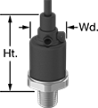
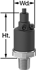
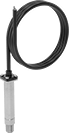
Pressure Transmitters
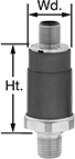
4 mA to 20 mA Output Signal—Wire Lead Connection
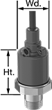 |
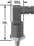
Transmitters with output current connect using two wires. The same wire is used to send a signal to the receiver and to power the transmitter. Current doesn’t lose signal over long distances and isn’t affected by electrical interference from other devices.
Pressure Range, psi | Max. Continuous Pressure, psi | Max. Short-Term Pressure, psi | Input Voltage, V DC | Ht. | Wd. | Enclosure Rating | Certification | For Use With | Accuracy | Housing Material | Connection Material | Temp. Range, ° F | Each | |||
|---|---|---|---|---|---|---|---|---|---|---|---|---|---|---|---|---|
1/4 NPT Male Pipe Connection | ||||||||||||||||
| 0 to 500 | 500 | 1,000 | 9 to 36 | 1 15/16" | 15/16" | IP67, NEMA 4X | UL Recognized Component, C-UL Recognized Component, CE Marked | Air Argon Diesel Fuel Gasoline Hydraulic Fluid Nitrogen Water | ±1.0% | Glass-Filled Nylon | 304 Stainless Steel | -40 to 255 | 3196K566 | 0000000 | ||
4 mA to 20 mA Output Signal—4-Pole M12 Plug Connection
 |
Transmitters with output current connect using two wires. The same wire is used to send a signal to the receiver and to power the transmitter. Current doesn’t lose signal over long distances and isn’t affected by electrical interference from other devices.
Transmitters with a M12 plug connection are compatible with M12 connectors.
Pressure Range, psi | Max. Continuous Pressure, psi | Max. Short-Term Pressure, psi | Input Voltage, V DC | Ht. | Wd. | Enclosure Rating | Certification | For Use With | Accuracy | Housing Material | Connection Material | Temp. Range, ° F | Each | |||
|---|---|---|---|---|---|---|---|---|---|---|---|---|---|---|---|---|
1/4 NPT Male Pipe Connection | ||||||||||||||||
| 0 to 500 | 500 | 1,000 | 9 to 36 | 1 11/16" | 15/16" | IP67, NEMA 4X | UL Recognized Component, C-UL Recognized Component, CE Marked | Air Argon Diesel Fuel Gasoline Hydraulic Fluid Nitrogen Water | ±1.0% | Glass-Filled Nylon | 304 Stainless Steel | -40 to 255 | 3196K127 | 0000000 | ||
4 mA to 20 mA Output Signal—DIN A Wire Connection
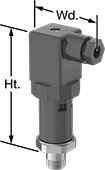 |
Transmitters with output current connect using two wires. The same wire is used to send a signal to the receiver and to power the transmitter. Current doesn’t lose signal over long distances and isn’t affected by electrical interference from other devices.
Pressure Range, psi | Max. Continuous Pressure, psi | Max. Short-Term Pressure, psi | Input Voltage, V DC | Electrical Connection Thread Size | Ht. | Wd. | Enclosure Rating | Certification | For Use With | Accuracy | Housing Material | Connection Material | Temp. Range, ° F | Each | |||
|---|---|---|---|---|---|---|---|---|---|---|---|---|---|---|---|---|---|
1/4 NPT Male Pipe Connection | |||||||||||||||||
| 0 to 500 | 500 | 1,000 | 9 to 36 | PG-9 | 3 7/16" | 1 5/16" | IP65, NEMA 4X | UL Recognized Component, C-UL Recognized Component, CE Marked | Air Argon Diesel Fuel Gasoline Hydraulic Fluid Nitrogen Water | ±1.0% | Glass-Filled Nylon | 304 Stainless Steel | -40 to 255 | 3196K606 | 0000000 | ||
4 mA to 20 mA Output Signal—DIN C Wire Connection
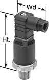 |
Transmitters with output current connect using two wires. The same wire is used to send a signal to the receiver and to power the transmitter. Current doesn’t lose signal over long distances and isn’t affected by electrical interference from other devices.
Pressure Transmitters with Calibration Certificate Traceable to NIST—Transmitters with calibration certificate traceable to NIST include documentation that states they've passed a test for accuracy.
Pressure Transmitters | Pressure Transmitters with Calibration Certificate Traceable to NIST | ||||||||||||||||||
|---|---|---|---|---|---|---|---|---|---|---|---|---|---|---|---|---|---|---|---|
Pressure Range, psi | Max. Continuous Pressure, psi | Max. Short-Term Pressure, psi | Input Voltage, V DC | Electrical Connection Thread Size | Ht. | Wd. | Enclosure Rating | Certification | For Use With | Accuracy | Housing Material | Connection Material | Temp. Range, ° F | Each | Each | ||||
1/8 NPT Male Pipe Connection | |||||||||||||||||||
| 0 to 500 | 500 | 1,000 | 9 to 36 | PG-7 | 2 5/8" | 1 3/8" | IP65, NEMA 4X | UL Recognized Component, C-UL Recognized Component, CE Marked | Air Argon Diesel Fuel Gasoline Hydraulic Fluid Nitrogen Water | ±1.0% | Glass-Filled Nylon | 304 Stainless Steel | -40 to 255 | 3196K384 | 0000000 | ——— | 0 | ||
1/4 NPT Male Pipe Connection | |||||||||||||||||||
| 0 to 500 | 500 | 1,000 | 9 to 36 | PG-7 | 2 5/8" | 1 3/8" | IP65, NEMA 4X | UL Recognized Component, C-UL Recognized Component, CE Marked | Air Argon Diesel Fuel Gasoline Hydraulic Fluid Nitrogen Water | ±1.0% | Glass-Filled Nylon | 304 Stainless Steel | -40 to 255 | 3196K58 | 000000 | 3196K78 | 0000000 | ||
4 mA to 20 mA Output Signal—Aptiv MP 150 Plug Connection
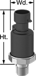 |
Transmitters with output current connect using two wires. The same wire is used to send a signal to the receiver and to power the transmitter. Current doesn’t lose signal over long distances and isn’t affected by electrical interference from other devices.
Pressure Range, psi | Max. Continuous Pressure, psi | Max. Short-Term Pressure, psi | Input Voltage, V DC | Ht. | Wd. | Enclosure Rating | Certification | For Use With | Accuracy | Housing Material | Connection Material | Temp. Range, ° F | Each | |||
|---|---|---|---|---|---|---|---|---|---|---|---|---|---|---|---|---|
1/4 NPT Male Pipe Connection | ||||||||||||||||
| 0 to 500 | 500 | 1,000 | 9 to 36 | 2 1/16" | 1 1/16" | IP67, NEMA 4X | UL Recognized Component, C-UL Recognized Component, CE Marked | Air Argon Diesel Fuel Gasoline Hydraulic Fluid Nitrogen Water | ±1.0% | Glass-Filled Nylon | 304 Stainless Steel | -40 to 255 | 3196K447 | 0000000 | ||
4 mA to 20 mA Output Signal—3-Pole DT Deutsch Style Plug Connection
 |
Transmitters with output current connect using two wires. The same wire is used to send a signal to the receiver and to power the transmitter. Current doesn’t lose signal over long distances and isn’t affected by electrical interference from other devices.
Pressure Range, psi | Max. Continuous Pressure, psi | Max. Short-Term Pressure, psi | Input Voltage, V DC | Ht. | Wd. | Enclosure Rating | Certification | For Use With | Accuracy | Housing Material | Connection Material | Temp. Range, ° F | Each | |||
|---|---|---|---|---|---|---|---|---|---|---|---|---|---|---|---|---|
1/4 NPT Male Pipe Connection | ||||||||||||||||
| 0 to 500 | 500 | 1,000 | 9 to 36 | 2 1/16" | 1 1/16" | IP67, NEMA 4X | UL Recognized Component, C-UL Recognized Component, CE Marked | Air Argon Diesel Fuel Gasoline Hydraulic Fluid Nitrogen Water | ±1.0% | Glass-Filled Nylon | 304 Stainless Steel | -40 to 255 | 3196K461 | 0000000 | ||
0V DC to 5V DC Output Signal—4-Pole Wire Lead Connection
|
Transmitters with output voltage connect using three wires—two wires into the power supply and a separate wire that sends a signal to the receiver. The receiver and the transmitter share a common ground wire back to the power supply.
Pressure Range, psi | Max. Continuous Pressure, psi | Max. Short-Term Pressure, psi | Input Voltage, V DC | Ht. | Wd. | Enclosure Rating | Certification | For Use With | Accuracy | Housing Material | Connection Material | Temp. Range, ° F | Each | |||
|---|---|---|---|---|---|---|---|---|---|---|---|---|---|---|---|---|
1/4 NPT Male Pipe Connection | ||||||||||||||||
| 0 to 500 | 500 | 1,000 | 9 to 36 | 1 15/16" | 15/16" | IP67, NEMA 4X | UL Recognized Component, C-UL Recognized Component, CE Marked | Air Argon Diesel Fuel Gasoline Hydraulic Fluid Nitrogen Water | ±1.0% | Glass-Filled Nylon | 304 Stainless Steel | -40 to 255 | 3196K523 | 0000000 | ||
1V DC to 5V DC Output Signal—Wire Lead Connection
|
Transmitters with output voltage connect using three wires—two wires into the power supply and a separate wire that sends a signal to the receiver. The receiver and the transmitter share a common ground wire back to the power supply.
Pressure Range, psi | Max. Continuous Pressure, psi | Max. Short-Term Pressure, psi | Input Voltage, V DC | Ht. | Wd. | Enclosure Rating | Certification | For Use With | Accuracy | Housing Material | Connection Material | Temp. Range, ° F | Each | |||
|---|---|---|---|---|---|---|---|---|---|---|---|---|---|---|---|---|
1/4 NPT Male Pipe Connection | ||||||||||||||||
| 0 to 500 | 500 | 1,000 | 9 to 36 | 1 15/16" | 15/16" | IP67, NEMA 4X | UL Recognized Component, C-UL Recognized Component, CE Marked | Air Argon Diesel Fuel Gasoline Hydraulic Fluid Nitrogen Water | ±1.0% | Glass-Filled Nylon | 304 Stainless Steel | -40 to 255 | 3196K537 | 0000000 | ||
1V DC to 5V DC Output Signal—4-Pole M12 Plug Connection
|
Transmitters with output voltage connect using three wires—two wires into the power supply and a separate wire that sends a signal to the receiver. The receiver and the transmitter share a common ground wire back to the power supply.
Transmitters with a M12 plug connection are compatible with M12 connectors.
Pressure Range, psi | Max. Continuous Pressure, psi | Max. Short-Term Pressure, psi | Input Voltage, V DC | Ht. | Wd. | Enclosure Rating | Certification | For Use With | Accuracy | Housing Material | Connection Material | Temp. Range, ° F | Each | |||
|---|---|---|---|---|---|---|---|---|---|---|---|---|---|---|---|---|
1/4 NPT Male Pipe Connection | ||||||||||||||||
| 0 to 500 | 500 | 1,000 | 9 to 36 | 1 11/16" | 7/8" | IP67, NEMA 4X | UL Recognized Component, C-UL Recognized Component, CE Marked | Air Argon Diesel Fuel Gasoline Hydraulic Fluid Nitrogen Water | ±1.0% | Glass-Filled Nylon | 304 Stainless Steel | -40 to 255 | 3196K508 | 0000000 | ||
1V DC to 5V DC Output Signal—DIN A Wire Connection
|
Transmitters with output voltage connect using three wires—two wires into the power supply and a separate wire that sends a signal to the receiver. The receiver and the transmitter share a common ground wire back to the power supply.
Pressure Range, psi | Max. Continuous Pressure, psi | Max. Short-Term Pressure, psi | Input Voltage, V DC | Electrical Connection Thread Size | Ht. | Wd. | Enclosure Rating | Certification | For Use With | Accuracy | Housing Material | Connection Material | Temp. Range, ° F | Each | |||
|---|---|---|---|---|---|---|---|---|---|---|---|---|---|---|---|---|---|
1/4 NPT Male Pipe Connection | |||||||||||||||||
| 0 to 500 | 500 | 1,000 | 9 to 36 | PG-9 | 3 7/16" | 1 5/16" | IP65, NEMA 4X | UL Recognized Component, C-UL Recognized Component, CE Marked | Air Argon Diesel Fuel Gasoline Hydraulic Fluid Nitrogen Water | ±1.0% | Glass-Filled Nylon | 304 Stainless Steel | -40 to 255 | 3196K579 | 0000000 | ||
1V DC to 5V DC Output Signal—DIN C Wire Connection
|
Transmitters with output voltage connect using three wires—two wires into the power supply and a separate wire that sends a signal to the receiver. The receiver and the transmitter share a common ground wire back to the power supply.
Pressure Range, psi | Max. Continuous Pressure, psi | Max. Short-Term Pressure, psi | Input Voltage, V DC | Electrical Connection Thread Size | Ht. | Wd. | Enclosure Rating | Certification | For Use With | Accuracy | Housing Material | Connection Material | Temp. Range, ° F | Each | |||
|---|---|---|---|---|---|---|---|---|---|---|---|---|---|---|---|---|---|
1/4 NPT Male Pipe Connection | |||||||||||||||||
| 0 to 500 | 500 | 1,000 | 9 to 36 | PG-7 | 2 5/8" | 1 3/8" | IP65, NEMA 4X | UL Recognized Component, C-UL Recognized Component, CE Marked | Air Argon Diesel Fuel Gasoline Hydraulic Fluid Nitrogen Water | ±1.0% | Glass-Filled Nylon | 304 Stainless Steel | -40 to 255 | 3196K344 | 0000000 | ||
0V DC to 10V DC Output Signal—Wire Lead Connection
|
Transmitters with output voltage connect using three wires—two wires into the power supply and a separate wire that sends a signal to the receiver. The receiver and the transmitter share a common ground wire back to the power supply.
Pressure Range, psi | Max. Continuous Pressure, psi | Max. Short-Term Pressure, psi | Input Voltage, V DC | Ht. | Wd. | Enclosure Rating | Certification | For Use With | Accuracy | Housing Material | Connection Material | Temp. Range, ° F | Each | |||
|---|---|---|---|---|---|---|---|---|---|---|---|---|---|---|---|---|
1/4 NPT Male Pipe Connection | ||||||||||||||||
| 0 to 500 | 500 | 1,000 | 14 to 36 | 1 15/16" | 15/16" | IP67, NEMA 4X | UL Recognized Component, C-UL Recognized Component, CE Marked | Air Argon Diesel Fuel Gasoline Hydraulic Fluid Nitrogen Water | ±1.0% | Glass-Filled Nylon | 304 Stainless Steel | -40 to 255 | 3196K552 | 0000000 | ||
0V DC to 10V DC Output Signal—4-Pole M12 Plug Connection
|
Transmitters with output voltage connect using three wires—two wires into the power supply and a separate wire that sends a signal to the receiver. The receiver and the transmitter share a common ground wire back to the power supply.
Transmitters with a M12 plug connection are compatible with M12 connectors.
Pressure Range, psi | Max. Continuous Pressure, psi | Max. Short-Term Pressure, psi | Input Voltage, V DC | Ht. | Wd. | Enclosure Rating | Certification | For Use With | Accuracy | Housing Material | Connection Material | Temp. Range, ° F | Each | |||
|---|---|---|---|---|---|---|---|---|---|---|---|---|---|---|---|---|
1/4 NPT Male Pipe Connection | ||||||||||||||||
| 0 to 500 | 500 | 1,000 | 14 to 36 | 1 11/16" | 15/16" | IP67, NEMA 4X | UL Recognized Component, C-UL Recognized Component, CE Marked | Air Argon Diesel Fuel Gasoline Hydraulic Fluid Nitrogen Water | ±1.0% | Glass-Filled Nylon | 304 Stainless Steel | -40 to 255 | 3196K331 | 0000000 | ||
0V DC to 10V DC Output Signal—DIN A Wire Connection
|
Transmitters with output voltage connect using three wires—two wires into the power supply and a separate wire that sends a signal to the receiver. The receiver and the transmitter share a common ground wire back to the power supply.
Pressure Range, psi | Max. Continuous Pressure, psi | Max. Short-Term Pressure, psi | Input Voltage, V DC | Electrical Connection Thread Size | Ht. | Wd. | Enclosure Rating | Certification | For Use With | Accuracy | Housing Material | Connection Material | Temp. Range, ° F | Each | |||
|---|---|---|---|---|---|---|---|---|---|---|---|---|---|---|---|---|---|
1/4 NPT Male Pipe Connection | |||||||||||||||||
| 0 to 500 | 500 | 1,000 | 14 to 36 | PG-9 | 3 7/16" | 1 5/16" | IP65, NEMA 4X | UL Recognized Component, C-UL Recognized Component, CE Marked | Air Argon Diesel Fuel Gasoline Hydraulic Fluid Nitrogen Water | ±1.0% | Glass-Filled Nylon | 304 Stainless Steel | -40 to 255 | 3196K593 | 0000000 | ||
0V DC to 10V DC Output Signal—DIN C Wire Connection
|
Transmitters with output voltage connect using three wires—two wires into the power supply and a separate wire that sends a signal to the receiver. The receiver and the transmitter share a common ground wire back to the power supply.
Pressure Transmitters with Calibration Certificate Traceable to NIST—Transmitters with calibration certificate traceable to NIST include documentation that states they've passed a test for accuracy.
Pressure Transmitters | Pressure Transmitters with Calibration Certificate Traceable to NIST | ||||||||||||||||||
|---|---|---|---|---|---|---|---|---|---|---|---|---|---|---|---|---|---|---|---|
Pressure Range, psi | Max. Continuous Pressure, psi | Max. Short-Term Pressure, psi | Input Voltage, V DC | Electrical Connection Thread Size | Ht. | Wd. | Enclosure Rating | Certification | For Use With | Accuracy | Housing Material | Connection Material | Temp. Range, ° F | Each | Each | ||||
1/4 NPT Male Pipe Connection | |||||||||||||||||||
| 0 to 500 | 500 | 1,000 | 14 to 36 | PG-7 | 2 5/8" | 1 3/8" | IP65, NEMA 4X | UL Recognized Component, C-UL Recognized Component, CE Marked | Air Argon Diesel Fuel Gasoline Hydraulic Fluid Nitrogen Water | ±1.0% | Glass-Filled Nylon | 304 Stainless Steel | -40 to 255 | 3196K208 | 0000000 | 3196K98 | 0000000 | ||
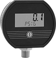
High-Accuracy Digital Pressure Test Gauges
Aluminum Case with 316 Stainless Steel Connection—Battery Powered
 | |
Bottom Connection |
Dial | Bottom Connection | |||||||||||||||
|---|---|---|---|---|---|---|---|---|---|---|---|---|---|---|---|---|
Pressure | Pressure Resolution, psi | Accuracy | Digit Ht. | Ht. | Wd. | Environment Temp. Range, ° F | Process Temp. Range, ° F | Enclosure Rating | Hazardous Location Rating | For Use With | Features | Batteries Included | Each | |||
NPT Male | ||||||||||||||||
1/4 Pipe Size | ||||||||||||||||
| 0 psi to 500 psi 0 MPa to 3.5 MPa 0 bar to 35 bar | 0.1 | ±0.25% Full Scale (Not Rated) | 1/2" | 2 7/8" | 3 3/8" | 0 to 185 | -40 to 200 | NEMA 2 | — | Air, Hydraulic Fluid, Water | 5-min. Automatic Shut-Off | Yes | 3943K122 | 0000000 | ||
| 0 psi to 500 psi 0 MPa to 3.5 MPa 0 bar to 35 bar | 0.1 | ±0.25% Full Scale (Not Rated) | 1/2" | 2 7/8" | 3 3/8" | 0 to 185 | -40 to 200 | NEMA 2 | Ex Ia IIC T4-T3; NEC Class I Divisions 1, 2 Groups A, B, C, D; NEC Zone 0 Groups IIC, IIB, IIA | Air, Diesel Fuel, Gasoline, Hydraulic Fluid, Natural Gas, Water | 5-min. Automatic Shut-Off | Yes | 3943K318 | 000000 | ||
NPT Male—Calibration Certificate Traceable to NIST | ||||||||||||||||
1/4 Pipe Size | ||||||||||||||||
| 0 psi to 500 psi 0 MPa to 3.5 MPa 0 bar to 35 bar | 0.1 | ±0.25% Full Scale (Not Rated) | 1/2" | 2 7/8" | 3 3/8" | 0 to 185 | -40 to 200 | NEMA 2 | — | Air, Hydraulic Fluid, Water | 5-min. Automatic Shut-Off | Yes | 3943K218 | 000000 | ||
| 0 psi to 500 psi 0 MPa to 3.5 MPa 0 bar to 35 bar | 0.1 | ±0.25% Full Scale (Not Rated) | 1/2" | 2 7/8" | 3 3/8" | 0 to 185 | -40 to 200 | NEMA 2 | Ex Ia IIC T4-T3; NEC Class I Divisions 1, 2 Groups A, B, C, D; NEC Zone 0 Groups IIC, IIB, IIA | Air, Diesel Fuel, Gasoline, Hydraulic Fluid, Natural Gas, Water | 5-min. Automatic Shut-Off | Yes | 3943K338 | 000000 | ||
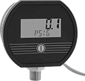
Aluminum Case with 316 Stainless Steel Connection—Electric 8-24V AC, 9-32V DC
 | |
Bottom Connection |
Dial | Bottom Connection | |||||||||||||
|---|---|---|---|---|---|---|---|---|---|---|---|---|---|---|
Pressure | Pressure Resolution, psi | Accuracy | Digit Ht. | Ht. | Wd. | Environment Temp. Range, ° F | Process Temp. Range, ° F | Enclosure Rating | For Use With | Wire Connection | Each | |||
NPT Male | ||||||||||||||
1/4 Pipe Size | ||||||||||||||
| 0 psi to 500 psi 0 MPa to 3.5 MPa 0 bar to 35 bar | 0.1 | ±0.25% Full Scale (Not Rated) | 1/2" | 2 7/8" | 3 3/8" | 0 to 185 | -40 to 200 | NEMA 2 | Air, Hydraulic Fluid, Water | Wire Leads | 3943K152 | 0000000 | ||
NPT Male—Calibration Certificate Traceable to NIST | ||||||||||||||
1/4 Pipe Size | ||||||||||||||
| 0 psi to 500 psi 0 MPa to 3.5 MPa 0 bar to 35 bar | 0.1 | ±0.25% Full Scale (Not Rated) | 1/2" | 2 7/8" | 3 3/8" | 0 to 185 | -40 to 200 | NEMA 2 | Air, Hydraulic Fluid, Water | Wire Leads | 3943K238 | 000000 | ||
Powder-Coated Aluminum Case with 316 Stainless Steel Connection—Electric 4-20 mA Output Signal
| |
Bottom Connection |
Dial | Bottom Connection | |||||||||||||||
|---|---|---|---|---|---|---|---|---|---|---|---|---|---|---|---|---|
Pressure, psi | Pressure Resolution, psi | Accuracy | Digit Ht. | Ht. | Wd. | Environment Temp. Range, ° F | Process Temp. Range, ° F | Case Color | Enclosure Rating | For Use With | Wire Connection | Input Voltage, V DC | Each | |||
NPT Male | ||||||||||||||||
1/4 Pipe Size | ||||||||||||||||
| 0 to 500 | 0.1 | ±0.25% Full Scale (Not Rated) | 1/2" | 2 7/8" | 3 3/8" | 0 to 185 | -40 to 200 | Blue, White | NEMA 2 | Air, Hydraulic Fluid, Water | Wire Leads | 8 to 32 | 2821K128 | 0000000 | ||
NPT Male—Calibration Certificate Traceable to NIST | ||||||||||||||||
1/4 Pipe Size | ||||||||||||||||
| 0 to 500 | 0.1 | ±0.25% Full Scale (Not Rated) | 1/2" | 2 7/8" | 3 3/8" | 0 to 185 | -40 to 200 | Blue, White | NEMA 2 | Air, Hydraulic Fluid, Water | Wire Leads | 8 to 32 | 2821K148 | 000000 | ||
Pressure and Vacuum Transmitters
4 mA to 20 mA Output Signal—Wire Leads
 |
Transmitters with current output connect using two wires. The same wire is used to send a signal to the receiver and to power the transmitter. Current doesn’t lose signal over long distances and isn’t affected by electrical interference from other devices.
IP67 Enclosure Rating—IP67 rated transmitters are protected from temporary submersion during washdowns.
Max. Pressure, psi | ||||||||||||||||
|---|---|---|---|---|---|---|---|---|---|---|---|---|---|---|---|---|
Pressure Range, psi | Vacuum Range, in. Hg | Continuous | Short-Term | Input Voltage, V DC | Pipe Size | Ht. | Wd. | Enclosure Rating | For Use With | Accuracy | Temp. Range, ° F | Connection Material | Each | |||
Glass-Filled Nylon Housing | ||||||||||||||||
| 0 to 500 | 0 to 30 | 1,000 | 1,000 | 9 to 36 | 1/4 NPT Male | 1 15/16" | 15/16" | IP67, NEMA 4X | Air, Argon, Diesel Fuel, Gasoline, Hydraulic Fluid, Nitrogen, Water | ±1.0% | -40 to 255 | 304 Stainless Steel | 4674N368 | 0000000 | ||
4 mA to 20 mA Output Signal—4-Pole M12 Plug-In Connection
 |
Transmitters with current output connect using two wires. The same wire is used to send a signal to the receiver and to power the transmitter. Current doesn’t lose signal over long distances and isn’t affected by electrical interference from other devices.
IP67 Enclosure Rating—IP67 rated transmitters are protected from temporary submersion during washdowns.
Max. Pressure, psi | ||||||||||||||||
|---|---|---|---|---|---|---|---|---|---|---|---|---|---|---|---|---|
Pressure Range, psi | Vacuum Range, in. Hg | Continuous | Short-Term | Input Voltage, V DC | Pipe Size | Ht. | Wd. | Enclosure Rating | For Use With | Accuracy | Temp. Range, ° F | Connection Material | Each | |||
Glass-Filled Nylon Housing | ||||||||||||||||
| 0 to 500 | 0 to 30 | 1,000 | 1,000 | 9 to 36 | 1/4 NPT Male | 1 11/16" | 7/8" | IP67, NEMA 4X | Air, Argon, Diesel Fuel, Gasoline, Hydraulic Fluid, Nitrogen, Water | ±1.0% | -40 to 255 | 304 Stainless Steel | 4674N371 | 0000000 | ||
4 mA to 20 mA Output Signal—DIN C Connection
 |
Transmitters with current output connect using two wires. The same wire is used to send a signal to the receiver and to power the transmitter. Current doesn’t lose signal over long distances and isn’t affected by electrical interference from other devices.
IP65 Enclosure Rating—IP65 rated transmitters are protected from dust and low-pressure jets of water.
Max. Pressure, psi | |||||||||||||||||
|---|---|---|---|---|---|---|---|---|---|---|---|---|---|---|---|---|---|
Pressure Range, psi | Vacuum Range, in. Hg | Continuous | Short-Term | Input Voltage, V DC | Pipe Size | Electrical Connection Thread Size | Ht. | Wd. | Enclosure Rating | For Use With | Accuracy | Temp. Range, ° F | Connection Material | Each | |||
Glass-Filled Nylon Housing | |||||||||||||||||
| 0 to 500 | 0 to 30 | 1,000 | 1,000 | 9 to 36 | 1/4 NPT Male | PG-7 | 2 1/2" | 15/16" | IP65, NEMA 4X | Air, Argon, Diesel Fuel, Gasoline, Hydraulic Fluid, Nitrogen, Water | ±1.0% | -40 to 255 | 304 Stainless Steel | 4674N369 | 0000000 | ||
1V DC to 5V DC Output Signal—Wire Leads
|
Transmitters with voltage output connect using three wires—two wires into the power supply and a separate wire that sends a signal to the receiver. The receiver and the transmitter share a common ground wire back to the power supply.
IP67 Enclosure Rating—IP67 rated transmitters are protected from temporary submersion during washdowns.
Max. Pressure, psi | ||||||||||||||||
|---|---|---|---|---|---|---|---|---|---|---|---|---|---|---|---|---|
Pressure Range, psi | Vacuum Range, in. Hg | Continuous | Short-Term | Input Voltage, V DC | Pipe Size | Ht. | Wd. | Enclosure Rating | For Use With | Accuracy | Temp. Range, ° F | Connection Material | Each | |||
Glass-Filled Nylon Housing | ||||||||||||||||
| 0 to 500 | 0 to 30 | 1,000 | 1,000 | 9 to 36 | 1/4 NPT Male | 1 15/16" | 15/16" | IP67, NEMA 4X | Air, Argon, Diesel Fuel, Gasoline, Hydraulic Fluid, Nitrogen, Water | ±1.0% | -40 to 255 | 304 Stainless Steel | 4674N363 | 0000000 | ||
0V DC to 10V DC Output Signal—Wire Leads
|
Transmitters with voltage output connect using three wires—two wires into the power supply and a separate wire that sends a signal to the receiver. The receiver and the transmitter share a common ground wire back to the power supply.
IP67 Enclosure Rating—IP67 rated transmitters are protected from temporary submersion during washdowns.
Max. Pressure, psi | ||||||||||||||||
|---|---|---|---|---|---|---|---|---|---|---|---|---|---|---|---|---|
Pressure Range, psi | Vacuum Range, in. Hg | Continuous | Short-Term | Input Voltage, V DC | Pipe Size | Ht. | Wd. | Enclosure Rating | For Use With | Accuracy | Temp. Range, ° F | Connection Material | Each | |||
Glass-Filled Nylon Housing | ||||||||||||||||
| 0 to 500 | 0 to 30 | 1,000 | 1,000 | 14 to 36 | 1/4 NPT Male | 1 15/16" | 15/16" | IP67, NEMA 4X | Air, Argon, Diesel Fuel, Gasoline, Hydraulic Fluid, Nitrogen, Water | ±1.0% | -40 to 255 | 304 Stainless Steel | 4674N353 | 0000000 | ||
0V DC to 10V DC Output Signal—DIN C Connection
|
Transmitters with voltage output connect using three wires—two wires into the power supply and a separate wire that sends a signal to the receiver. The receiver and the transmitter share a common ground wire back to the power supply.
IP65 Enclosure Rating—IP65 rated transmitters are protected from dust and low-pressure jets of water.
Max. Pressure, psi | |||||||||||||||||
|---|---|---|---|---|---|---|---|---|---|---|---|---|---|---|---|---|---|
Pressure Range, psi | Vacuum Range, in. Hg | Continuous | Short-Term | Input Voltage, V DC | Pipe Size | Electrical Connection Thread Size | Ht. | Wd. | Enclosure Rating | For Use With | Accuracy | Temp. Range, ° F | Connection Material | Each | |||
Glass-Filled Nylon Housing | |||||||||||||||||
| 0 to 500 | 0 to 30 | 1,000 | 1,000 | 14 to 36 | 1/4 NPT Male | PG-7 | 2 1/2" | 15/16" | IP65, NEMA 4X | Air, Argon, Diesel Fuel, Gasoline, Hydraulic Fluid, Nitrogen, Water | ±1.0% | -40 to 255 | 304 Stainless Steel | 4674N37 | 0000000 | ||
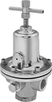
DIN-Mount Precision Compressed Air Regulators
Relieving Regulators
 |
Pipe Size | Overall | |||||||||||||||
|---|---|---|---|---|---|---|---|---|---|---|---|---|---|---|---|---|
Pressure Regulation, psi | Inlet | Outlet | Max. Flow Rate @ Pressure | Max. Pressure, psi | Gauge Included | No. of Gauge Ports | For DIN Rail Ht., mm | Wd. | Ht. | Housing Material | Max. Temp., ° F | Includes | Each | |||
NPT Female Inlet × NPT Female Outlet | ||||||||||||||||
±0.2% Regulating Accuracy | ||||||||||||||||
| 0 to 10 | 1/4 | 1/4 | 60 scfm @ 100 psi | 500 | No | 1 | 35 | 3" | 7" | Aluminum | 200 | DIN-Rail Mounting Bracket, Wall-Mounting Bracket | 1810T11 | 0000000 | ||
| 0 to 10 | 3/8 | 3/8 | 60 scfm @ 100 psi | 500 | No | 1 | 35 | 3" | 7" | Aluminum | 200 | DIN-Rail Mounting Bracket, Wall-Mounting Bracket | 1810T21 | 000000 | ||
| 0 to 10 | 1/2 | 1/2 | 60 scfm @ 100 psi | 500 | No | 1 | 35 | 3" | 7" | Aluminum | 200 | DIN-Rail Mounting Bracket, Wall-Mounting Bracket | 1810T31 | 000000 | ||
| 0.5 to 30 | 1/4 | 1/4 | 60 scfm @ 100 psi | 500 | No | 1 | 35 | 3" | 7" | Aluminum | 200 | DIN-Rail Mounting Bracket, Wall-Mounting Bracket | 1810T12 | 000000 | ||
| 0.5 to 30 | 3/8 | 3/8 | 60 scfm @ 100 psi | 500 | No | 1 | 35 | 3" | 7" | Aluminum | 200 | DIN-Rail Mounting Bracket, Wall-Mounting Bracket | 1810T22 | 000000 | ||
| 0.5 to 30 | 1/2 | 1/2 | 60 scfm @ 100 psi | 500 | No | 1 | 35 | 3" | 7" | Aluminum | 200 | DIN-Rail Mounting Bracket, Wall-Mounting Bracket | 1810T32 | 000000 | ||
| 1 to 60 | 1/4 | 1/4 | 60 scfm @ 100 psi | 500 | No | 1 | 35 | 3" | 7" | Aluminum | 200 | DIN-Rail Mounting Bracket, Wall-Mounting Bracket | 1810T13 | 000000 | ||
| 1 to 60 | 3/8 | 3/8 | 60 scfm @ 100 psi | 500 | No | 1 | 35 | 3" | 7" | Aluminum | 200 | DIN-Rail Mounting Bracket, Wall-Mounting Bracket | 1810T23 | 000000 | ||
| 1 to 60 | 1/2 | 1/2 | 60 scfm @ 100 psi | 500 | No | 1 | 35 | 3" | 7" | Aluminum | 200 | DIN-Rail Mounting Bracket, Wall-Mounting Bracket | 1810T33 | 000000 | ||
| 2 to 150 | 1/4 | 1/4 | 60 scfm @ 100 psi | 500 | No | 1 | 35 | 3" | 7" | Aluminum | 200 | DIN-Rail Mounting Bracket, Wall-Mounting Bracket | 1810T14 | 000000 | ||
| 2 to 150 | 3/8 | 3/8 | 60 scfm @ 100 psi | 500 | No | 1 | 35 | 3" | 7" | Aluminum | 200 | DIN-Rail Mounting Bracket, Wall-Mounting Bracket | 1810T24 | 000000 | ||
| 2 to 150 | 1/2 | 1/2 | 60 scfm @ 100 psi | 500 | No | 1 | 35 | 3" | 7" | Aluminum | 200 | DIN-Rail Mounting Bracket, Wall-Mounting Bracket | 1810T34 | 000000 | ||
| 5 to 300 | 1/4 | 1/4 | 60 scfm @ 100 psi | 500 | No | 1 | 35 | 3" | 7" | Aluminum | 200 | DIN-Rail Mounting Bracket, Wall-Mounting Bracket | 1810T15 | 000000 | ||
| 5 to 300 | 3/8 | 3/8 | 60 scfm @ 100 psi | 500 | No | 1 | 35 | 3" | 7" | Aluminum | 200 | DIN-Rail Mounting Bracket, Wall-Mounting Bracket | 1810T25 | 000000 | ||
| 5 to 300 | 1/2 | 1/2 | 60 scfm @ 100 psi | 500 | No | 1 | 35 | 3" | 7" | Aluminum | 200 | DIN-Rail Mounting Bracket, Wall-Mounting Bracket | 1810T35 | 000000 | ||
| 5 to 400 | 1/4 | 1/4 | 60 scfm @ 100 psi | 500 | No | 1 | 35 | 3" | 7" | Aluminum | 200 | DIN-Rail Mounting Bracket, Wall-Mounting Bracket | 1810T16 | 000000 | ||
| 5 to 400 | 3/8 | 3/8 | 60 scfm @ 100 psi | 500 | No | 1 | 35 | 3" | 7" | Aluminum | 200 | DIN-Rail Mounting Bracket, Wall-Mounting Bracket | 1810T26 | 000000 | ||
| 5 to 400 | 1/2 | 1/2 | 60 scfm @ 100 psi | 500 | No | 1 | 35 | 3" | 7" | Aluminum | 200 | DIN-Rail Mounting Bracket, Wall-Mounting Bracket | 1810T36 | 000000 | ||
Tank-Mount Pressure-Regulating Valves for Fuel Gases
Single Stage
 |  |  |  |
Male Outlet × Female Inlet Single-Stage Valve With T-Handle | Male Outlet × Female Inlet Single-Stage Valve With Knob | Male Outlet × Male Inlet Single-Stage Valve With T-Handle | Male Outlet × Male Inlet Single-Stage Valve With Knob |
Inlet | Outlet | Material | ||||||||||||||
|---|---|---|---|---|---|---|---|---|---|---|---|---|---|---|---|---|
CGA No. | Location | Thread Direction | Pressure Gauge Reading Range, psi | Thread Size | Location | Thread Direction | Pressure Range, psi | Pressure Adjustment Method | Body | Seal | Diaphragm | Temp. Range, ° F | Each | |||
For Acetylene | ||||||||||||||||
UNF Male Outlet × NGO Female Inlet | ||||||||||||||||
| 300 | Side | Right Hand | 0 to 400 | 9/16"-18 | Side | Left Hand | 0 to 15 | T-Handle | Brass | PTFE | Rubber | -20 to 120 | 7897A2 | 0000000 | ||
| 300 | Side | Right Hand | 0 to 400 | 9/16"-18 | Side | Left Hand | 0 to 15 | Knob | Brass/Steel | PTFE | Rubber | -20 to 120 | 7897A62 | 000000 | ||
UNF Male Outlet × NGO Male Inlet | ||||||||||||||||
| 510 | Side | Left Hand | 0 to 400 | 9/16"-18 | Side | Left Hand | 0 to 15 | T-Handle | Brass | PTFE | Rubber | -20 to 120 | 7897A7 | 000000 | ||
| 510 | Side | Left Hand | 0 to 400 | 9/16"-18 | Side | Left Hand | 0 to 15 | T-Handle | Brass | PTFE | Stainless Steel | -20 to 120 | 7897A53 | 000000 | ||
| 510 | Side | Left Hand | 0 to 400 | 9/16"-18 | Side | Left Hand | 0 to 15 | Knob | Brass/Steel | PTFE | Rubber | -20 to 120 | 7897A63 | 000000 | ||
For Propane and Propylene | ||||||||||||||||
UNF Male Outlet × NGO Male Inlet | ||||||||||||||||
| 510 | Side | Left Hand | 0 to 400 | 9/16"-18 | Side | Left Hand | 5 to 50 | Knob | Brass/Steel | PTFE | Rubber | -20 to 120 | 7897A66 | 000000 | ||
Two Stage
 |  |
Male Outlet × Female Inlet Two-Stage Valve With T-Handle | Male Outlet × Male Inlet Two-Stage Valve With T-Handle |
Two-stage valves progressively reduce pressure over two steps for more consistent outlet pressure at all times. They’re often used in applications that require a constant outlet pressure regardless of the tank level.
Brass Body—Valves with a brass body have a longer service life than valves with a brass and steel body.
Inlet | Outlet | Material | ||||||||||||||
|---|---|---|---|---|---|---|---|---|---|---|---|---|---|---|---|---|
CGA No. | Location | Thread Direction | Pressure Gauge Reading Range, psi | Thread Size | Location | Thread Direction | Pressure Range, psi | Pressure Adjustment Method | Body | Seal | Diaphragm | Temp. Range, ° F | Each | |||
For Acetylene | ||||||||||||||||
UNF Male Outlet × NGO Female Inlet | ||||||||||||||||
| 300 | Side | Right Hand | 0 to 400 | 9/16"-18 | Side | Left Hand | 0 to 15 | T-Handle | Brass/Steel | PTFE | Rubber | -20 to 120 | 7897A4 | 0000000 | ||
UNF Male Outlet × NGO Male Inlet | ||||||||||||||||
| 510 | Side | Left Hand | 0 to 400 | 9/16"-18 | Side | Left Hand | 0 to 15 | T-Handle | Brass/Steel | PTFE | Rubber | -20 to 120 | 7897A14 | 000000 | ||
For Propane and Propylene | ||||||||||||||||
UNF Male Outlet × NGO Male Inlet | ||||||||||||||||
| 510 | Side | Left Hand | 0 to 400 | 9/16"-18 | Side | Left Hand | 0 to 50 | T-Handle | Brass/Steel | PTFE | Rubber | -20 to 120 | 7897A18 | 000000 | ||
Economy Pressure Transmitters
4 mA to 20 mA Output Signal—Wire Lead Connection
 |
Pressure Range, psi | Max. Continuous Pressure, psi | Max. Short-Term Pressure, psi | Input Voltage, V DC | Ht. | Wd. | Enclosure Rating | Certification | For Use With | Accuracy | Housing Material | Connection Material | Temp. Range, ° F | Each | |||
|---|---|---|---|---|---|---|---|---|---|---|---|---|---|---|---|---|
1/4 NPT Male Pipe Connection | ||||||||||||||||
| 0 to 500 | 500 | 750 | 12 to 36 | 1 13/16" | 15/16" | IP65 | CE Marked | Air Argon Diesel Fuel Hydraulic Fluid Nitrogen Water | ±1.5% | 304 Stainless Steel | 304 Stainless Steel | -20 to 220 | 6017N17 | 0000000 | ||
Cleaned and Bagged Pressure-Regulating Valves for Air and Inert Gas
 |
Often used for oxygen service and other high-purity applications, these valves are cleaned and bagged to meet CGA G-4.1 standards to prevent contamination. They automatically reduce a high, variable inlet pressure to a lower, stable outlet pressure. Adjust the outlet pressure within the range. Valves have two gauge ports. They are no-bleed style, so they keep process gases contained in the valve.
Inlet | Outlet | Gauge Port | ||||||||||||||||
|---|---|---|---|---|---|---|---|---|---|---|---|---|---|---|---|---|---|---|
Pipe Size | Location | Max. Pressure, psi | Pipe Size | Location | Pressure Adjustment Method | Pressure Gauge Included | Pipe Size | Location | Connection | End-to-End Lg. | For Use With | Temp. Range, ° F | Specs. Met | Choose an Outlet Pressure, psi | Each | |||
NPT Female | ||||||||||||||||||
Brass Body—Buna-N Diaphragm and Fluoroelastomer Seal | ||||||||||||||||||
| 1/2 | Side | 500 | 1/2 | Side | T-Handle | No | 1/4 | Side | NPT Female | 2 13/16" | Nitrogen, Oxygen, Argon, Helium, Neon | -40 to 165 | CGA G-4.1 | 5 to 55, 40 to 110, 100 to 200, 175 to 300 | 49305K21 | 0000000 | ||
| 3/4 | Side | 500 | 3/4 | Side | T-Handle | No | 1/4 | Side | NPT Female | 3 5/16" | Nitrogen, Oxygen, Argon, Helium, Neon | -40 to 165 | CGA G-4.1 | 5 to 55, 40 to 110, 100 to 200, 175 to 275 | 49305K22 | 000000 | ||
| 1 | Side | 500 | 1 | Side | T-Handle | No | 1/4 | Side | NPT Female | 3 5/16" | Nitrogen, Oxygen, Argon, Helium, Neon | -40 to 165 | CGA G-4.1 | 5 to 55, 40 to 110, 100 to 200, 175 to 275 | 49305K23 | 000000 | ||
High-Purity Tank-Mount Pressure-Regulating Valves for Fuel Gases
 |
Two Stage |
Designed to reduce contaminants in high-purity applications using hydrogen and methane gas, these valves have a smooth finish to reduce dust collection and internal components designed to protect the seal and diaphragm from contamination. They’re often used in research sample systems, emission monitoring systems, and chromatography. Valves automatically reduce a high inlet pressure from compressed gas tanks to a lower, stable outlet pressure. All have Compressed Gas Association (CGA) numbered inlet fittings for secure connections to compressed gas tanks. Choose a valve with the same CGA number as your tank and other system components. Outlet fittings are Swagelok® for a leak-free seal around hard metal tubing in high-pressure lines. Also known as instrumentation fittings, Swagelok® fittings are compatible with Parker A-Lok, Gyrolok, Bilok, and Tylok fittings. Valves come with a gauge to monitor outlet pressure and a gauge to monitor inlet pressure from the tank.
Choose a valve with a maximum outlet pressure that’s approximately twice your application’s normal operating pressure. Your operating pressure should never exceed 75% of the valve’s maximum outlet pressure.
Two Stage—Two-stage valves progressively reduce pressure over two steps for more consistent outlet pressure at all times. They’re often used in applications that require a constant outlet pressure regardless of the tank level.
Inlet | Outlet | |||||||||||||
|---|---|---|---|---|---|---|---|---|---|---|---|---|---|---|
CGA No. | Location | Thread Direction | Pressure Gauge Reading Range, psi | No. of Stages | For Tube OD | Location | Pressure Range, psi | Pressure Adjustment Method | For Use With | Temp. Range, ° F | Each | |||
NGO Female Inlet × Swagelok® Female Outlet | ||||||||||||||
Brass Body—316 Stainless Steel Diaphragm and PTFE Seal with Relief Valve | ||||||||||||||
| 350 | Side | Left Hand | 0 to 4,000 | Two | 1/4" | Side | 0 to 500 | Knob | Hydrogen, Methane | -20 to 120 | 7951A71 | 0000000 | ||
Tank-Mount Pressure-Regulating Valves for Cryogenic Cylinders
 |
Automatically reduce a high inlet pressure from compressed gas tanks to a lower, stable outlet pressure. These valves can remove gases from liquid cryogenic cylinders. They have Compressed Gas Association (CGA) numbered inlet fittings for secure connections to compressed gas tanks. Choose a valve with the same CGA number as your tank and other system components. Valves come with a gauge to monitor outlet pressure. They are single stage and reduce pressure in one step, which causes the outlet pressure to fluctuate slightly as you empty the tank.
Choose a valve with a maximum outlet pressure that’s approximately twice your application’s normal operating pressure. Your operating pressure should never exceed 75% of the valve’s maximum outlet pressure.
Inlet | Outlet | |||||||||||||
|---|---|---|---|---|---|---|---|---|---|---|---|---|---|---|
For Use With | CGA No. | Location | Thread Direction | No. of Stages | Thread Size | Location | Thread Direction | Pressure Range, psi | Pressure Adjustment Method | Temp. Range, ° F | Each | |||
UNF Male Outlet × NGO Female Inlet | ||||||||||||||
Brass Body—Stainless Steel Diaphragm and PTFE Seal | ||||||||||||||
| Carbon Dioxide | 320 | Side | Right Hand | Single | 9/16"-18 | Bottom | Right Hand | 0 to 350 | T-Handle | -20 to 120 | 7897A83 | 0000000 | ||
UNF Male Outlet × NGO Male Inlet | ||||||||||||||
Brass Body—Stainless Steel Diaphragm and PTFE Seal | ||||||||||||||
| Nitrogen, Argon | 580 | Side | Right Hand | Single | 9/16"-18 | Bottom | Right Hand | 0 to 350 | T-Handle | -20 to 120 | 7897A87 | 000000 | ||
Corrosion-Resistant Pressure Test Gauges
304 Stainless Steel Case with 316 Stainless Steel Connection—Single Scale (Pounds per Square Inch)
 | |
Bottom Connection | Bottom Connection |
Pressure, psi | Bottom Connection | |||||||||
|---|---|---|---|---|---|---|---|---|---|---|
Range | Graduations | Numeric Increments | Accuracy | Environment Temp. Range, ° F | Process Temp. Range, ° F | For Use With | Each | |||
NPT Male—Calibration Certificate Traceable to NIST | ||||||||||
4 1/2" Diameter Dial—1/2 Pipe Size | ||||||||||
| 0 to 500 | 5 | 50 | ±0.5% Full Scale (Grade 2A) | -40 to 150 | -40 to 225 | Air, Hydraulic Fluid, Natural Gas, Water | 3702K449 | 0000000 | ||
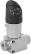
Pressure-Regulating Valves for Fuel Gases
 |
With T-Handle |
Install these valves directly in gas distribution pipelines for acetylene, hydrogen, or propane. They automatically reduce a high inlet pressure to a lower, stable outlet pressure. Valves have two outlets to fit various pipe configurations and come with a plug to close the unused outlet. The gauge monitors outlet pressure. All valves are single stage and reduce pressure in one step, which causes the outlet pressure to fluctuate.
Choose a valve with a maximum outlet pressure that’s approximately twice your application’s normal operating pressure. Your operating pressure should never exceed 75% of the valve’s maximum outlet pressure.
Inlet | Outlet | Lg. | ||||||||||||
|---|---|---|---|---|---|---|---|---|---|---|---|---|---|---|
For Use With | Pipe Size | Location | Max. Pressure, psi | Pipe Size | Location | Pressure Adjustment Method | Pressure Gauge Measurement Range, psi | Temp. Range, ° F | End-to-End | Port-to-Port | Each | |||
NPT Female | ||||||||||||||
Brass Body—Stainless Steel Diaphragm and Neoprene Seal | ||||||||||||||
| Hydrogen, Propane | 1/4 | Side | 500 | 1/4 | Bottom, Side | T-Handle | 0 to 200 | 0 to 120 | 2.400" | 1.01" | 7864A12 | 0000000 | ||
Cleaned and Bagged Panel-Mount Pressure-Regulating Valves for Air and Inert Gas
Commonly used for oxygen service and other high-purity applications, these valves come cleaned and bagged to prevent contamination. All automatically reduce a high, variable inlet pressure to a lower, stable outlet pressure. Adjust the outlet pressure within the range. Valves have threads below the adjustment knob and come with a panel-mount nut. They can also be surface mounted. All have two gauge ports. Body is 316 stainless steel for exceptional corrosion resistance. Valves are no-bleed style, so they keep process gases contained in the valve.
Inlet | Outlet | Gauge Port | ||||||||||||||||
|---|---|---|---|---|---|---|---|---|---|---|---|---|---|---|---|---|---|---|
Pipe Size | Location | Max. Pressure, psi | Pipe Size | Location | Pressure Range, psi | Pressure Adjustment Method | Pressure Gauge Included | Pipe Size | Location | Connection | End-to-End Lg. | Panel Cutout Dia. | For Use With | Temp. Range, ° F | Each | |||
NPT Female | ||||||||||||||||||
316 Stainless Steel Body—316 Stainless Steel Diaphragm and PTFE Seal | ||||||||||||||||||
| 1/4 | Side | 3,500 | 1/4 | Side | 0 to 500 | Knob | No | 1/4 | Side | NPT Female | 5 3/8" | 1.37" | Air, Nitrogen, Argon, Helium | -40 to 165 | 8166T44 | 0000000 | ||
| 1/2 | Side | 500 | 1/2 | Side | 0 to 25 | Knob | No | 1/4 | Side | NPT Female | 5 1/2" | 1.37" | Air, Nitrogen, Argon, Helium | -40 to 165 | 8166T45 | 00000000 | ||
| 1/2 | Side | 500 | 1/2 | Side | 0 to 100 | Knob | No | 1/4 | Side | NPT Female | 5 1/2" | 1.37" | Air, Nitrogen, Argon, Helium | -40 to 165 | 8166T46 | 00000000 | ||
| 1/2 | Side | 500 | 1/2 | Side | 0 to 150 | Knob | No | 1/4 | Side | NPT Female | 5 1/2" | 1.37" | Air, Nitrogen, Argon, Helium | -40 to 165 | 8166T47 | 00000000 | ||
Sanitary Pressure Transmitters
4 mA to 20 mA Output Signal—5-Pole M12 Plug Connection
 |
For Tube OD | For Flange OD | Pressure Range, psi | Max. Continuous Pressure, psi | Max. Short-Term Pressure, psi | Input Voltage, V DC | Ht. | Wd. | Enclosure Rating | Food Industry Std. | Certification | For Use With | Accuracy | Housing Material | Connection Material | Temp. Range, ° F | Each | |||
|---|---|---|---|---|---|---|---|---|---|---|---|---|---|---|---|---|---|---|---|
Connects to Quick-Clamp Tube | |||||||||||||||||||
| 1 1/2" | 1.984" | 0 to 500 | 500 | 1,000 | 10 to 40 | 2 5/16" | 2 7/16" | IP66, IP69K, NEMA 4X | 3-A Certified 74-06 | CE Marked | Air Argon Diesel Fuel Gasoline Hydraulic Fluid Nitrogen Water | ±0.5% | 304 Stainless Steel | 316 Stainless Steel | 30 to 300 | 2954N125 | 0000000 | ||
| 2" | 2.516" | 0 to 500 | 500 | 1,000 | 10 to 40 | 2 5/16" | 2 7/16" | IP66, IP69K, NEMA 4X | 3-A Certified 74-06 | CE Marked | Air Argon Diesel Fuel Gasoline Hydraulic Fluid Nitrogen Water | ±0.5% | 304 Stainless Steel | 316 Stainless Steel | 30 to 300 | 2954N135 | 000000 | ||
Hazardous-Location Pressure Transmitters
4 mA to 20 mA Output Signal—Wire Lead Connection
 |
Pressure Range, psi | Max. Continuous Pressure, psi | Max. Short-Term Pressure, psi | Input Voltage, V DC | Ht. | Wd. | Hazardous Location Rating | Enclosure Rating | Certification | For Use With | Accuracy | Housing Material | Connection Material | Temp. Range, ° F | Each | |||
|---|---|---|---|---|---|---|---|---|---|---|---|---|---|---|---|---|---|
1/4 NPT Male Pipe Connection | |||||||||||||||||
| 0 to 500 | 500 | 875 | 10 to 30 | 3 5/16" | 1 1/16" | NEC Class I Divisions 1, 2 Groups A, B, C, D | IP67 | CE Marked, CSA Certified, FM Approved | Air Argon Diesel Fuel Gasoline Hydraulic Fluid Nitrogen Water | ±0.25% | 316 Stainless Steel | 316 Stainless Steel | -40 to 130 | 5484N14 | 0000000 | ||
Absolute Pressure Transmitters
4 mA to 20 mA Output Signal—Wire Lead Connection
 |
Transmitters with output current connect using two wires. The same wire is used to send a signal to the receiver and to power the transmitter. Current doesn’t lose signal over long distances and isn’t affected by electrical interference from other devices.
NEMA 4X Enclosure Rating—Transmitters that are rated NEMA 4X also protect against weather and corrosion.
Pressure Range, psi | Max. Continuous Pressure, psi | Max. Short-Term Pressure, psi | Input Voltage, V DC | Ht. | Wd. | Enclosure Rating | Certification | For Use With | Accuracy | Housing Material | Connection Material | Temp. Range, ° F | Each | |||
|---|---|---|---|---|---|---|---|---|---|---|---|---|---|---|---|---|
1/4 NPT Male Pipe Connection | ||||||||||||||||
| 0 to 500 | 1,000 | 1,000 | 9 to 36 | 1 15/16" | 15/16" | IP67, NEMA 4X | UL Recognized Component, C-UL Recognized Component, CE Marked | Air Argon Diesel Fuel Gasoline Hydraulic Fluid Nitrogen Water | ±1.5% | Glass-Filled Nylon | 316L Stainless Steel | -40 to 255 | 3861N17 | 0000000 | ||
Differential Pressure Transmitters for Liquids
316 Stainless Steel Housing%20--%3e%3csvg%20version='1.1'%20id='Layer_1'%20xmlns='http://www.w3.org/2000/svg'%20xmlns:xlink='http://www.w3.org/1999/xlink'%20x='0px'%20y='0px'%20viewBox='0%200%20400%20400'%20style='enable-background:new%200%200%20400%20400;'%20xml:space='preserve'%3e%3cstyle%20type='text/css'%3e%20.st0{fill:%231A70A0;}%20.st1{opacity:0.5;}%20%3c/style%3e%3cg%3e%3cg%3e%3cpath%20class='st0'%20d='M200,56.9c38.35,0,74.4,14.93,101.51,42.05c27.11,27.11,42.05,63.17,42.05,101.51s-14.93,74.4-42.05,101.51%20S238.35,344.02,200,344.02s-74.4-14.93-101.51-42.05c-27.11-27.11-42.05-63.17-42.05-101.51s14.93-74.4,42.05-101.51%20S161.65,56.9,200,56.9%20M200,12.9C96.41,12.9,12.44,96.88,12.44,200.46c0,103.59,83.97,187.56,187.56,187.56%20c103.59,0,187.56-83.97,187.56-187.56C387.56,96.88,303.59,12.9,200,12.9L200,12.9z'/%3e%3c/g%3e%3cg%3e%3cg%20class='st1'%3e%3cpath%20class='st0'%20d='M235.49,152.24h16.15l-27.46,111.87c-1.94,7.8-2.91,12.5-2.91,14.1c0,1.82,0.58,3.29,1.73,4.41%20c1.16,1.12,2.69,1.68,4.61,1.68c5.23,0,11.78-3.85,19.63-11.55l17.22,21.34c-16.95,17.33-34.87,26-53.78,26%20c-8.37,0-15.45-1.47-21.23-4.41c-5.79-2.94-10.44-7.25-13.95-12.92c-3.51-5.67-5.27-11.18-5.27-16.53c0-1.93,0.35-5.24,1.05-9.94%20c1-6.94,2.05-12.54,3.15-16.82l15.22-62.15h-32.69l7.65-30.97C190.89,163.58,214.53,158.88,235.49,152.24z%20M230.44,80.84%20c8.24,0,14.66,2.62,19.26,7.86c4.6,5.24,6.9,11.55,6.9,18.94c0,5.46-1.42,10.7-4.25,15.73c-2.83,5.03-6.88,9.07-12.12,12.12%20c-5.24,3.05-10.33,4.57-15.24,4.57c-4.6,0-9.17-1.23-13.72-3.69c-4.55-2.46-8.02-5.78-10.43-9.95%20c-2.41-4.17-3.61-8.67-3.61-13.48c0-5.35,1.52-10.64,4.57-15.89c3.05-5.24,7.03-9.25,11.96-12.04%20C218.68,82.23,224.24,80.84,230.44,80.84z'/%3e%3c/g%3e%3cg%3e%3cpath%20class='st0'%20d='M214.08,152.24h16.15l-27.46,111.87c-1.94,7.8-2.91,12.5-2.91,14.1c0,1.82,0.58,3.29,1.73,4.41%20c1.16,1.12,2.69,1.68,4.61,1.68c5.23,0,11.78-3.85,19.63-11.55l17.22,21.34c-16.95,17.33-34.87,26-53.78,26%20c-8.37,0-15.45-1.47-21.23-4.41c-5.79-2.94-10.44-7.25-13.95-12.92c-3.51-5.67-5.27-11.18-5.27-16.53c0-1.93,0.35-5.24,1.05-9.94%20c1-6.94,2.05-12.54,3.15-16.82l15.22-62.15h-32.69l7.65-30.97C169.48,163.58,193.11,158.88,214.08,152.24z%20M209.03,80.84%20c8.24,0,14.66,2.62,19.26,7.86c4.6,5.24,6.9,11.55,6.9,18.94c0,5.46-1.42,10.7-4.25,15.73c-2.83,5.03-6.88,9.07-12.12,12.12%20c-5.24,3.05-10.33,4.57-15.24,4.57c-4.6,0-9.17-1.23-13.72-3.69c-4.55-2.46-8.02-5.78-10.43-9.95%20c-2.41-4.17-3.61-8.67-3.61-13.48c0-5.35,1.52-10.64,4.57-15.89c3.05-5.24,7.03-9.25,11.96-12.04%20C197.26,82.23,202.83,80.84,209.03,80.84z'/%3e%3c/g%3e%3c/g%3e%3c/g%3e%3c/svg%3e)
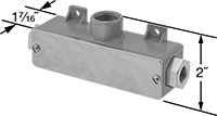 |
IP66 Enclosure Rating— IP66 rated transmitters are dust tight and protect against washdowns.
NEMA 4X Enclosure Rating—NEMA 4X rated transmitters protect against weather, washdowns, and corrosion.
Mounting Holes | Connection | ||||||||||||||||||||
|---|---|---|---|---|---|---|---|---|---|---|---|---|---|---|---|---|---|---|---|---|---|
Pressure Differential, psi | Max. Input Pressure, psi | Input Voltage, V DC | Pipe Size | For No. of Wires | Mounting Hardware Included | Dia. | No. of | Ht. | Wd. | Certification | Enclosure Rating | For Use With | Accuracy | Pipe | Fitting | Material | Temp. Range, ° F | Each | |||
4 to 20 mA Output Signal—Screw Terminals | |||||||||||||||||||||
| 0 to 100 | 500 | 10 to 35 | 1/4 | 2 | No | 1/4" | 2 | 2" | 1 7/16" | CE Marked | IP66, NEMA 4X | Diesel Fuel, Gasoline, Hydraulic Fluid, Water | ±0.5% | NPT Female | Threaded | 316 Stainless Steel | 0 to 200 | 3257N15 | 0000000 | ||
Differential Pressure Transmitters with Electronic Switch Outputs
 |
Configurable Analog Transmitter Output | Configurable Digital Switch Output | Mounting Holes | Connection | |||||||||||||||||||
|---|---|---|---|---|---|---|---|---|---|---|---|---|---|---|---|---|---|---|---|---|---|---|
Pressure Differential, psi | Max. Input Pressure, psi | Input Voltage, V DC | Pipe Size | Ht. | Wd. | No. of | Analog Signal | No. of | Digital Signal | Mounting Hardware Included | Dia. | No. of | Enclosure Rating | For Use With | Accuracy | Pipe | Material | Temp. Range, ° F | Each | |||
5 Poles M12 Plug In | ||||||||||||||||||||||
Glass-Filled Polyester Plastic Housing | ||||||||||||||||||||||
| 0 to 500 | 2,500 | 15 to 32 | 1/4 | 4 13/16" | 3" | 1 | 0 to 10V DC, 4 to 20 mA | 2 | PNP, NPN | No | 3/16" | 2 | IP65, IP67, NEMA 4X, NEMA 6 | Air, Hydraulic Fluid, Water | ±0.5% | NPT Female | 316L Stainless Steel | 14 to 158 | 4682N13 | 000000000 | ||
Tank-Mount Pressure-Regulating Valves for Air and Inert Gas
Single Stage
Inlet | Outlet | Material | |||||||||||||
|---|---|---|---|---|---|---|---|---|---|---|---|---|---|---|---|
CGA No. | Location | Thread Direction | Pressure Gauge Reading Range, psi | Location | Thread Direction | Pressure Range, psi | Pressure Adjustment Method | Body | Seal | Diaphragm | Temp. Range, ° F | Each | |||
For Argon, Helium, and Nitrogen | |||||||||||||||
45° Flared UN/UNF (SAE 45°) Male Outlet × NGO Male Inlet | |||||||||||||||
| 580 | Side | Right Hand | 0 to 4,000 | Side | Right Hand | 0 to 500 | T-Handle | Brass | PTFE | Neoprene | -20 to 120 | 66325A23 | 0000000 | ||
Pressure Transmitters for Oxygen
4 mA to 20 mA Output Signal—Wire Lead Connection
 |
Pressure Range, psi | Max. Continuous Pressure, psi | Max. Short-Term Pressure, psi | Input Voltage, V DC | Ht. | Wd. | Enclosure Rating | Certification | For Use With | Accuracy | Housing Material | Connection Material | Temp. Range, ° F | Each | |||
|---|---|---|---|---|---|---|---|---|---|---|---|---|---|---|---|---|
1/4 NPT Male Pipe Connection | ||||||||||||||||
| 0 to 500 | 1,000 | 1,000 | 9 to 36 | 2 3/8" | 1 5/16" | IP65, NEMA 4X | UL Recognized Component, C-UL Recognized Component, CE Marked | Oxygen | ±1.0% | Glass-Filled Nylon | 304 Stainless Steel | -40 to 255 | 3914A15 | 0000000 | ||
High-Purity Tank-Mount Pressure-Regulating Valves for Inert Gas
For Argon, Helium, and Nitrogen
 |
Chrome-Plated Brass Body—Chrome-plated valves add a layer of corrosion resistance.
Single Stage—Single-stage valves reduce pressure in one step, which causes the outlet pressure to fluctuate slightly as you empty the tank. They’re best for applications where a constant outlet pressure isn’t critical.
Inlet | Outlet | ||||||||||||
|---|---|---|---|---|---|---|---|---|---|---|---|---|---|
CGA No. | Location | Thread Direction | Pressure Gauge Reading Range, psi | No. of Stages | For Tube OD | Location | Pressure Range, psi | Pressure Adjustment Method | Temp. Range, ° F | Each | |||
NGO Male Inlet × Swagelok® Female Outlet | |||||||||||||
Chrome-Plated Brass Body—316 Stainless Steel Diaphragm and PTFE Seal | |||||||||||||
| 580 | Side | Right Hand | 0 to 4,000 | Single | 1/4" | Side | 0 to 500 | Knob | -20 to 120 | 7951A76 | 0000000 | ||
Adjustable-Range Pressure Transmitters
 |
±1% Accuracy | ±0.5% Accuracy | |||||||||||||||||
|---|---|---|---|---|---|---|---|---|---|---|---|---|---|---|---|---|---|---|
Pressure Range, psi | Max. Continuous Pressure, psi | Max. Short-Term Pressure, psi | Input Voltage, V DC | Pipe Size | Ht. | Wd. | Enclosure Rating | For Use With | Pipe Connection | Housing Material | Connection Material | Temp. Range, ° F | Each | Each | ||||
4 mA to 20 mA Output Signal—Wire Lead Connection | ||||||||||||||||||
| 0 to 500 | 500 | 1,000 | 10 to 36 | 1/4 | 3" | 7/8" | NEMA 4X | Air Diesel Fuel Gasoline Hydraulic Fluid Water | NPT Male | 304 Stainless Steel | 304 Stainless Steel | -20 to 180 | 31685K629 | 0000000 | 31685K646 | 0000000 | ||
1V DC to 5V DC Output Signal—Wire Lead Connection | ||||||||||||||||||
| 0 to 500 | 500 | 1,000 | 10 to 36 | 1/4 | 3" | 7/8" | NEMA 4X | Air Diesel Fuel Gasoline Hydraulic Fluid Water | NPT Male | 304 Stainless Steel | 304 Stainless Steel | -20 to 180 | 31685K617 | 000000 | 31685K638 | 000000 | ||
