Filter by
System of Measurement
Maximum Pressure
Connection Location
For Use With

Measurement Unit
Fitting Connection

Pressure Numeric Increments
Connection Material
Dial Type

DFARS Specialty Metals
Export Control Classification Number (ECCN)

About Pressure Gauges
Find a gauge with the right connection material and dial type—many with traceable calibration certificates.
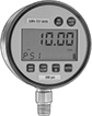
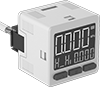
Digital-Display High-Accuracy Pressure Gauges
Polycarbonate Case with 17-4 PH Stainless Steel Connection—(Pounds per Square Inch, Atmospheres, Bar, Kilograms per Square Centimeter)
 | |
Bottom Connection |
Pressure Gauges | 9V Alkaline Disposable Batteries | |||||||||||||||||||
|---|---|---|---|---|---|---|---|---|---|---|---|---|---|---|---|---|---|---|---|---|
Temp. Range, ° F | Batteries | Bottom Connection | ||||||||||||||||||
Ht. | Wd. | Dp. | Pipe Size | Case Color | Environment | Process | Included | Size | No. of Req. | Features | For Use With | Accuracy | Choose a Pressure Range | Each | Pkg. Qty. | Pkg. | ||||
Any-Angle Mount | ||||||||||||||||||||
NPT Female | ||||||||||||||||||||
| 4 1/16" | 2 11/16" | 1 7/8" | 1/8 | Gray | -40 to 150 | 35 to 130 | No | 9V | 1 | 1-hr. Automatic Shut-Off | Air | ±0.5% Full Scale (Not Rated) | 0 to 100 psi/0 to 6.8 atm/0 to 6.8 bar/0 to 7 kg per cm², 0 to 1,000 psi/0 to 68 atm/0 to 68.9 bar/0 to 70.3 kg per cm² | 3840K911 | 0000000 | 1 | 71455K56 | 00000 | ||
ABS Case with Brass Connection—(Pounds per Square Inch, Bar, Kilograms per Square Centimeter, Megapascals)
 |  |
Center-Back Connection |
Temp. Range, ° F | Batteries | Center-Back Connection | ||||||||||||
|---|---|---|---|---|---|---|---|---|---|---|---|---|---|---|
Dial Dia. | Pipe Size | Case Color | Environment | Process | Included | Size | Features | For Use With | Accuracy | Pressure Range | Each | |||
Any-Angle Mount | ||||||||||||||
NPT Male | ||||||||||||||
| 1 3/4" | 1/8 | Black | -10 to 140 | -10 to 140 | Yes | CR2450 | 5-min. Automatic Shut-Off | Air Carbon Dioxide Hydrogen Natural Gas Nitrogen | ±1% Full Scale (Grade 1A) | 0 to 145 psi/0 to 10 bar/0 to 10 kg per cm²/0 to 1 MPa | 1287N1 | 000000 | ||
| 1 3/4" | 1/4 | Black | -10 to 140 | -10 to 140 | Yes | CR2450 | 5-min. Automatic Shut-Off | Air Carbon Dioxide Hydrogen Natural Gas Nitrogen | ±1% Full Scale (Grade 1A) | 0 to 145 psi/0 to 10 bar/0 to 10 kg per cm²/0 to 1 MPa | 1287N2 | 00000 | ||
NPT Male with Calibration Certificate Traceable to NIST | ||||||||||||||
| 1 3/4" | 1/8 | Black | -10 to 140 | -10 to 140 | Yes | CR2450 | 5-min. Automatic Shut-Off | Air Carbon Dioxide Hydrogen Natural Gas Nitrogen | ±1% Full Scale (Grade 1A) | 0 to 145 psi/0 to 10 bar/0 to 10 kg per cm²/0 to 1 MPa | 1287N311 | 000000 | ||
| 1 3/4" | 1/4 | Black | -10 to 140 | -10 to 140 | Yes | CR2450 | 5-min. Automatic Shut-Off | Air Carbon Dioxide Hydrogen Natural Gas Nitrogen | ±1% Full Scale (Grade 1A) | 0 to 145 psi/0 to 10 bar/0 to 10 kg per cm²/0 to 1 MPa | 1287N312 | 000000 | ||
3-in-1 Pressure and Vacuum Gauges
 | |
Bottom Connection |
These portable gauges have three different dials to display pressure and vacuum measurements on a low, medium, and high scale. Also known as compound gauges, they measure both pressure and vacuum in hydraulic applications.
Left Gauge | Bottom Connection | |||||||||||||
|---|---|---|---|---|---|---|---|---|---|---|---|---|---|---|
Dial Dia. | Pipe Size | Pressure Range | Vacuum Range | Middle Gauge Pressure Range | Right Gauge Pressure Range | Environment Temp. Range, ° F | Process Temp. Range, ° F | Overall Dia. | For Use With | Accuracy | Each | |||
Steel Case with Steel Connection—Dual Scale (Centimeters of Mercury, Inches of Mercury, Kilograms per Square Centimeter, Pounds per Square Inch) | ||||||||||||||
NPTF Male | ||||||||||||||
| 2" | 1/8 | 0 psi to 150 psi, 0 kg/cm² to 10 kg/cm² | 0 in. Hg to 30 in. Hg, 0 cm Hg to 76 cm Hg | 0 psi to 5,000 psi; 0 kg/cm² to 350 kg/cm² | 0 psi to 600 psi, 0 kg/cm² to 42 kg/cm² | -40 to 120 | -40 to 190 | 6 7/16" | Air, Hydraulic Fluid | ±2% Midscale (Grade B) | 4054K64 | 0000000 | ||
Ultra-High-Accuracy Digital Pressure Test Gauges
304 Stainless Steel Case with 316 Stainless Steel Connection—Battery Powered
 | |
Bottom Connection | ||||||||||||||
|---|---|---|---|---|---|---|---|---|---|---|---|---|---|---|
Pressure | Pressure Resolution, psi | Accuracy | Environment Temp. Range, ° F | Process Temp. Range, ° F | Enclosure Rating | Hazardous Location Rating | Features | Digit Ht. | For Use With | Batteries Included | Each | |||
NPT Male—Calibration Certificate Traceable to NIST | ||||||||||||||
3" Diameter Dial—1/4 Pipe Size | ||||||||||||||
| 0 psi to 10 psi 0 in. H₂O to 270 in. H₂O 0 kPa to 65 kPa 0 MPa to 0.06 MPa 0 bar to 0.6 bar 0 kg/cm² to 0.7 kg/cm² | 0.001 | ±0.05% Full Scale (Grade 5A) | -40 to 180 | 0 to 150 | IP65 | NEC Class I Divisions 1, 2 Groups A, B, C, D; NEC Class II Divisions 1, 2 Groups E, F, G; NEC Class III Divisions 1, 2 | Configurable Automatic Shut-Off (2 min., 5 min., 15 min., 30 min., or Never) | 1 1/8" | Air, Diesel Fuel, Gasoline, Hydraulic Fluid, Natural Gas, Water | Yes | 3584K11 | 000000000 | ||
| 0 psi to 15 psi 0 in. H₂O to 410 in. H₂O 0 kPa to 100 kPa 0 MPa to 0.1 MPa 0 bar to 1 bar 0 kg/cm² to 1 kg/cm² | 0.001 | ±0.05% Full Scale (Grade 5A) | -40 to 180 | 0 to 150 | IP65 | NEC Class I Divisions 1, 2 Groups A, B, C, D; NEC Class II Divisions 1, 2 Groups E, F, G; NEC Class III Divisions 1, 2 | Configurable Automatic Shut-Off (2 min., 5 min., 15 min., 30 min., or Never) | 1 1/8" | Air, Diesel Fuel, Gasoline, Hydraulic Fluid, Natural Gas, Water | Yes | 3584K12 | 00000000 | ||
| 0 psi to 30 psi 0 in. H₂O to 830 in. H₂O 0 kPa to 200 kPa 0 MPa to 0.2 MPa 0 bar to 2 bar 0 kg/cm² to 2 kg/cm² | 0.001 | ±0.05% Full Scale (Grade 5A) | -40 to 180 | 0 to 150 | IP65 | NEC Class I Divisions 1, 2 Groups A, B, C, D; NEC Class II Divisions 1, 2 Groups E, F, G; NEC Class III Divisions 1, 2 | Configurable Automatic Shut-Off (2 min., 5 min., 15 min., 30 min., or Never) | 1 1/8" | Air, Diesel Fuel, Gasoline, Hydraulic Fluid, Natural Gas, Water | Yes | 3584K13 | 00000000 | ||
| 0 psi to 60 psi 0 in. H₂O to 1,600 in. H₂O 0 kPa to 410 kPa 0 MPa to 0.4 MPa 0 bar to 4 bar 0 kg/cm² to 4 kg/cm² | 0.001 | ±0.05% Full Scale (Grade 5A) | -40 to 180 | 0 to 150 | IP65 | NEC Class I Divisions 1, 2 Groups A, B, C, D; NEC Class II Divisions 1, 2 Groups E, F, G; NEC Class III Divisions 1, 2 | Configurable Automatic Shut-Off (2 min., 5 min., 15 min., 30 min., or Never) | 1 1/8" | Air, Diesel Fuel, Gasoline, Hydraulic Fluid, Natural Gas, Water | Yes | 3584K14 | 00000000 | ||
| 0 psi to 100 psi 0 in. H₂O to 2,700 in. H₂O 0 kPa to 680 kPa 0 MPa to 0.6 MPa 0 bar to 6 bar 0 kg/cm² to 7 kg/cm² | 0.01 | ±0.05% Full Scale (Grade 5A) | -40 to 180 | 0 to 150 | IP65 | NEC Class I Divisions 1, 2 Groups A, B, C, D; NEC Class II Divisions 1, 2 Groups E, F, G; NEC Class III Divisions 1, 2 | Configurable Automatic Shut-Off (2 min., 5 min., 15 min., 30 min., or Never) | 1 1/8" | Air, Diesel Fuel, Gasoline, Hydraulic Fluid, Natural Gas, Water | Yes | 3584K15 | 00000000 | ||
| 0 psi to 160 psi 0 in. H₂O to 4,400 in. H₂O 0 kPa to 1,100 kPa 0 MPa to 1.1 MPa 0 bar to 11 bar 0 kg/cm² to 11 kg/cm² | 0.01 | ±0.05% Full Scale (Grade 5A) | -40 to 180 | 0 to 150 | IP65 | NEC Class I Divisions 1, 2 Groups A, B, C, D; NEC Class II Divisions 1, 2 Groups E, F, G; NEC Class III Divisions 1, 2 | Configurable Automatic Shut-Off (2 min., 5 min., 15 min., 30 min., or Never) | 1 1/8" | Air, Diesel Fuel, Gasoline, Hydraulic Fluid, Natural Gas, Water | Yes | 3584K16 | 00000000 | ||
| 0 psi to 200 psi 0 in. H₂O to 5,500 in. H₂O 0 kPa to 1,300 kPa 0 MPa to 1.3 MPa 0 bar to 13 bar 0 kg/cm² to 14 kg/cm² | 0.01 | ±0.05% Full Scale (Grade 5A) | -40 to 180 | 0 to 150 | IP65 | NEC Class I Divisions 1, 2 Groups A, B, C, D; NEC Class II Divisions 1, 2 Groups E, F, G; NEC Class III Divisions 1, 2 | Configurable Automatic Shut-Off (2 min., 5 min., 15 min., 30 min., or Never) | 1 1/8" | Air, Diesel Fuel, Gasoline, Hydraulic Fluid, Natural Gas, Water | Yes | 3584K17 | 00000000 | ||
| 0 psi to 300 psi 0 in. H₂O to 8,300 in. H₂O 0 kPa to 2,000 kPa 0 MPa to 2 MPa 0 bar to 20 bar 0 kg/cm² to 20 kg/cm² | 0.01 | ±0.05% Full Scale (Grade 5A) | -40 to 180 | 0 to 150 | IP65 | NEC Class I Divisions 1, 2 Groups A, B, C, D; NEC Class II Divisions 1, 2 Groups E, F, G; NEC Class III Divisions 1, 2 | Configurable Automatic Shut-Off (2 min., 5 min., 15 min., 30 min., or Never) | 1 1/8" | Air, Diesel Fuel, Gasoline, Hydraulic Fluid, Natural Gas, Water | Yes | 3584K18 | 00000000 | ||
| 0 psi to 600 psi 0 in. H₂O to 16,600 in. H₂O 0 kPa to 4,100 kPa 0 MPa to 4 MPa 0 bar to 40 bar 0 kg/cm² to 40 kg/cm² | 0.01 | ±0.05% Full Scale (Grade 5A) | -40 to 180 | 0 to 150 | IP65 | NEC Class I Divisions 1, 2 Groups A, B, C, D; NEC Class II Divisions 1, 2 Groups E, F, G; NEC Class III Divisions 1, 2 | Configurable Automatic Shut-Off (2 min., 5 min., 15 min., 30 min., or Never) | 1 1/8" | Air, Diesel Fuel, Gasoline, Hydraulic Fluid, Natural Gas, Water | Yes | 3584K19 | 00000000 | ||
| 0 psi to 800 psi 0 in. H₂O to 22,100 in. H₂O 0 kPa to 5,500 kPa 0 MPa to 5 MPa 0 bar to 55 bar 0 kg/cm² to 55 kg/cm² | 0.01 | ±0.05% Full Scale (Grade 5A) | -40 to 180 | 0 to 150 | IP65 | NEC Class I Divisions 1, 2 Groups A, B, C, D; NEC Class II Divisions 1, 2 Groups E, F, G; NEC Class III Divisions 1, 2 | Configurable Automatic Shut-Off (2 min., 5 min., 15 min., 30 min., or Never) | 1 1/8" | Air, Diesel Fuel, Gasoline, Hydraulic Fluid, Natural Gas, Water | Yes | 3584K21 | 00000000 | ||
| 0 psi to 1,000 psi 0 in. H₂O to 27,700 in. H₂O 0 kPa to 6,800 kPa 0 MPa to 6 MPa 0 bar to 65 bar 0 kg/cm² to 70 kg/cm² | 0.1 | ±0.05% Full Scale (Grade 5A) | -40 to 180 | 0 to 150 | IP65 | NEC Class I Divisions 1, 2 Groups A, B, C, D; NEC Class II Divisions 1, 2 Groups E, F, G; NEC Class III Divisions 1, 2 | Configurable Automatic Shut-Off (2 min., 5 min., 15 min., 30 min., or Never) | 1 1/8" | Air, Diesel Fuel, Gasoline, Hydraulic Fluid, Natural Gas, Water | Yes | 3584K22 | 00000000 | ||
| 0 psi to 2,000 psi 0 in. H₂O to 55,400 in. H₂O 0 kPa to 13,700 kPa 0 MPa to 13 MPa 0 bar to 135 bar 0 kg/cm² to 140 kg/cm² | 0.1 | ±0.05% Full Scale (Grade 5A) | -40 to 180 | 0 to 150 | IP65 | NEC Class I Divisions 1, 2 Groups A, B, C, D; NEC Class II Divisions 1, 2 Groups E, F, G; NEC Class III Divisions 1, 2 | Configurable Automatic Shut-Off (2 min., 5 min., 15 min., 30 min., or Never) | 1 1/8" | Air, Diesel Fuel, Gasoline, Hydraulic Fluid, Natural Gas, Water | Yes | 3584K24 | 00000000 | ||
| 0 psi to 3,000 psi 0 in. H₂O to 83,100 in. H₂O 0 kPa to 20,600 kPa 0 MPa to 20 MPa 0 bar to 205 bar 0 kg/cm² to 210 kg/cm² | 0.1 | ±0.05% Full Scale (Grade 5A) | -40 to 180 | 0 to 150 | IP65 | NEC Class I Divisions 1, 2 Groups A, B, C, D; NEC Class II Divisions 1, 2 Groups E, F, G; NEC Class III Divisions 1, 2 | Configurable Automatic Shut-Off (2 min., 5 min., 15 min., 30 min., or Never) | 1 1/8" | Air, Diesel Fuel, Gasoline, Hydraulic Fluid, Natural Gas, Water | Yes | 3584K25 | 00000000 | ||
| 0 psi to 5,000 psi 0 kPa to 34,400 kPa 0 MPa to 30 MPa 0 bar to 340 bar 0 kg/cm² to 350 kg/cm² | 0.1 | ±0.05% Full Scale (Grade 5A) | -40 to 180 | 0 to 150 | IP65 | NEC Class I Divisions 1, 2 Groups A, B, C, D; NEC Class II Divisions 1, 2 Groups E, F, G; NEC Class III Divisions 1, 2 | Configurable Automatic Shut-Off (2 min., 5 min., 15 min., 30 min., or Never) | 1 1/8" | Air, Diesel Fuel, Gasoline, Hydraulic Fluid, Natural Gas, Water | Yes | 3584K26 | 00000000 | ||
Low-Pressure Gauges for Chemicals
Painted Steel Case with PVC Connection—Dual Scale (Pounds per Square Inch, Kilograms per Square Centimeter)
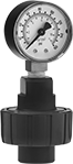 |  |
PVC Guard | Bottom Connection (PVC, CPVC, and Polypropylene Guards) |
Temp. Range, ° F | Bottom Connection | ||||||||||||
|---|---|---|---|---|---|---|---|---|---|---|---|---|---|
Dial Dia. | Pipe Size | Case Color | Environment | Process | For Use With | Accuracy | Guard Material | Guard Color | Choose a Pressure Range | Each | |||
NPT Female | |||||||||||||
| 2" | 1/4 | Black | 40 to 140 | 40 to 140 | Boric Acid Carbon Dioxide Hydraulic Fluid Salt Water Sodium Hypochlorite (Bleach) Water | ±2% Midscale (Grade B) | PVC | Gray | 0 to 30 psi/0 to 2.1 kg per cm², 0 to 60 psi/0 to 4.2 kg per cm², 0 to 150 psi/0 to 11.2 kg per cm² | 4091K23 | 0000000 | ||
| 2" | 1/2 | Black | 40 to 140 | 40 to 140 | Boric Acid Carbon Dioxide Hydraulic Fluid Salt Water Sodium Hypochlorite (Bleach) Water | ±2% Midscale (Grade B) | PVC | Gray | 0 to 30 psi/0 to 2.1 kg per cm², 0 to 60 psi/0 to 4.2 kg per cm², 0 to 150 psi/0 to 11.2 kg per cm² | 4091K24 | 000000 | ||
Painted Steel Case with CPVC Connection—Dual Scale (Pounds per Square Inch, Kilograms per Square Centimeter)
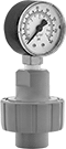 | |
CPVC Guard | Bottom Connection (PVC, CPVC, and Polypropylene Guards) |
Temp. Range, ° F | Bottom Connection | ||||||||||||
|---|---|---|---|---|---|---|---|---|---|---|---|---|---|
Dial Dia. | Pipe Size | Case Color | Environment | Process | For Use With | Accuracy | Guard Material | Guard Color | Choose a Pressure Range | Each | |||
NPT Female | |||||||||||||
| 2" | 1/4 | Black | 40 to 190 | 40 to 190 | Boric Acid Carbon Dioxide Hydraulic Fluid Salt Water Sodium Hypochlorite (Bleach) Water | ±2% Midscale (Grade B) | CPVC | Gray | 0 to 30 psi/0 to 2.1 kg per cm², 0 to 60 psi/0 to 4.2 kg per cm², 0 to 150 psi/0 to 11.2 kg per cm² | 4147K41 | 0000000 | ||
| 2" | 1/2 | Black | 40 to 190 | 40 to 190 | Boric Acid Carbon Dioxide Hydraulic Fluid Salt Water Sodium Hypochlorite (Bleach) Water | ±2% Midscale (Grade B) | CPVC | Gray | 0 to 30 psi/0 to 2.1 kg per cm², 0 to 60 psi/0 to 4.2 kg per cm², 0 to 150 psi/0 to 11.2 kg per cm² | 4147K42 | 000000 | ||
Painted Steel Case with Polypropylene Connection—Dual Scale (Pounds per Square Inch, Kilograms per Square Centimeter)
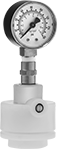 | |
Polypropylene Guard | Bottom Connection (PVC, CPVC, and Polypropylene Guards) |
Temp. Range, ° F | Bottom Connection | ||||||||||||
|---|---|---|---|---|---|---|---|---|---|---|---|---|---|
Dial Dia. | Pipe Size | Case Color | Environment | Process | For Use With | Accuracy | Guard Material | Guard Color | Choose a Pressure Range | Each | |||
NPT Female | |||||||||||||
| 2" | 1/4 | Black | 40 to 240 | 40 to 240 | Boric Acid Carbon Dioxide Hydraulic Fluid Salt Water Water | ±2% Midscale (Grade B) | Polypropylene | White | 0 to 30 psi/0 to 2.1 kg per cm², 0 to 60 psi/0 to 4.2 kg per cm², 0 to 150 psi/0 to 11.2 kg per cm² | 4134K23 | 0000000 | ||
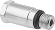
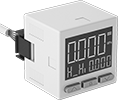
Pressure Transmitters for Compressed Air
 |
With a pressure range common to most compressed air systems, use these transmitters to monitor your system's air pressure. Also known as transducers, these transmitters convert pressure to an electrical signal that can be interpreted by receiving devices such as remote displays and motor speed controls. They can also connect to a programmable logic controller (PLC) with two digital PNP switch outputs, so you can activate automated controls or alarms when a set pressure is reached. They have a digital display with buttons to change settings.
For your receiving device to interpret the signal from the transmitter, you will need to calibrate it for the transmitter's pressure range and output signal. As pressure increases, the output signal from the transmitter will increase. Transmitters will only provide accurate readings within the rated pressure range.
UL and C-UL recognized components, CSA certified, and CE marked, they meet American, Canadian, and European safety standards.
Transmitters with Wire Lead Connection
Analog Transmitter Output | Digital Switch Output | Pressure, psi | |||||||||||||||||||
|---|---|---|---|---|---|---|---|---|---|---|---|---|---|---|---|---|---|---|---|---|---|
Analog Signal | No. of | Digital Signal | No. of | Range | Set Point Range | Max. Continuous Pressure, psi | Max. Short-Term Pressure, psi | Input Voltage, V DC | Ht. | Wd. | Enclosure Rating | Certification | For Use With | Accuracy | Housing Material | Connection Material | Temp. Range, ° F | Each | |||
1/8 NPT Male Pipe Connection | |||||||||||||||||||||
| 2.4 mA to 20 mA | 1 | PNP | 2 | 14.5 to 145 | 14.5 to 145 | 145 | 218 | 12 to 24 | 1 3/16" | 1 3/16" | IP40 | UL Recognized Component, C-UL Recognized Component, CE Marked, CSA Certified | Air Argon Nitrogen | ±0.2% | Polybutylene | Nickel-Plated Brass | 25 to 120 | 4276N13 | 000000 | ||
| 0.6V DC to 5V DC | 1 | PNP | 2 | 14.5 to 145 | 14.5 to 145 | 145 | 218 | 12 to 24 | 1 3/16" | 1 3/16" | IP40 | UL Recognized Component, C-UL Recognized Component, CE Marked, CSA Certified | Air Argon Nitrogen | ±0.2% | Polybutylene | Nickel-Plated Brass | 25 to 120 | 4276N11 | 00000 | ||
1/4" OD Push-to-Connect Tube Connection | |||||||||||||||||||||
| 2.4 mA to 20 mA | 1 | PNP | 2 | 14.5 to 145 | 14.5 to 145 | 145 | 218 | 12 to 24 | 1 3/16" | 1 3/16" | IP40 | UL Recognized Component, C-UL Recognized Component, CE Marked, CSA Certified | Air Argon Nitrogen | ±0.2% | Polybutylene | Nickel-Plated Brass | 25 to 120 | 4276N14 | 00000 | ||
| 0.6V DC to 5V DC | 1 | PNP | 2 | 14.5 to 145 | 14.5 to 145 | 145 | 218 | 12 to 24 | 1 3/16" | 1 3/16" | IP40 | UL Recognized Component, C-UL Recognized Component, CE Marked, CSA Certified | Air Argon Nitrogen | ±0.2% | Polybutylene | Nickel-Plated Brass | 25 to 120 | 4276N12 | 00000 | ||
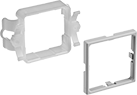 |
For Panel Cutout | |||||
|---|---|---|---|---|---|
Ht. | Wd. | Mounting Hole Style | Each | ||
| 1 7/32" | 1 7/32" | Straight | 3167K22 | 00000 | |
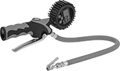
Inflator Tire Gauges
Indicator Bar Readout
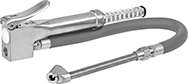 | 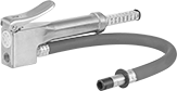 |
Angled Head 2 Heads | With One Straight Head |
Indicator bar readouts slide out of the top of the gauge to display pressure readings.
Rubber Sleeve—Gauges with a rubber sleeve prevent metal-to-metal contact with your tire to avoid damaging it.
Hose | Air Inlet | Air Outlet | |||||||||||||||
|---|---|---|---|---|---|---|---|---|---|---|---|---|---|---|---|---|---|
Head Type | No. of Heads | Pressure Range | Pressure Numeric Increments, psi | Indicator Bar Material | Lg. | Material | Connection Port | Pipe Size | Thread Type | Thread Size | Thread Type | Schrader Valve Connection Type | Features | Each | |||
Zinc-Plated Zinc Alloy | |||||||||||||||||
| Angled | 2 | 10 psi to 120 psi, 1 kg/cm² to 5 kg/cm² | 2 | Brass | 12" | Rubber | Pipe | 1/4 | NPT | 0.305"-32 | Schrader | Press-and-Hold | Rubber Sleeve | 6113A102 | 000000 | ||
| Straight | 1 | 10 psi to 90 psi, 1 kg/cm² to 5 kg/cm² | 2 | Brass | 12" | Rubber | Pipe | 1/4 | NPT | 0.305"-32 | Schrader | Press-and-Hold | Rubber Sleeve | 6113A101 | 00000 | ||
Digital Readout
 | 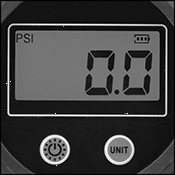 |
Straight Head 1 Head |
Hose | Air Inlet | Air Outlet | ||||||||||||||
|---|---|---|---|---|---|---|---|---|---|---|---|---|---|---|---|---|
Head Type | No. of Heads | Pressure Range | Pressure Numeric Increments, psi | Lg., ft. | Material | Connection Port | Pipe Size | Thread Type | Thread Size | Thread Type | Specs. Met | Schrader Valve Connection Type | Each | |||
Chrome-Plated Zinc Alloy | ||||||||||||||||
| Straight | 1 | 0 psi to 150 psi; 0 kPa to 1,030 kPa | 0.1 | 5 | Rubber | Pipe | 1/4 | NPT | 0.305"-32 | Schrader | OSHA Compliant 29 CFR 1910.177 | Clip On | 6647A101 | 0000000 | ||
| Straight | 1 | 0 psi to 150 psi; 0 kPa to 1,030 kPa | 0.1 | 10 | Rubber | Pipe | 1/4 | NPT | 0.305"-32 | Schrader | OSHA Compliant 29 CFR 1910.177 | Clip On | 6647A103 | 000000 | ||
| Straight | 1 | 0 psi to 150 psi; 0 kPa to 1,030 kPa | 0.1 | 15 | Rubber | Pipe | 1/4 | NPT | 0.305"-32 | Schrader | OSHA Compliant 29 CFR 1910.177 | Clip On | 6647A102 | 000000 | ||
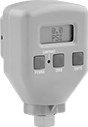
Pressure and Vacuum Transmitters for Compressed Air
 |
Specifically made for compressed air and gas systems, these transmitters remotely monitor pressure and vacuum. Also known as transducers, they convert both pressure and vacuum into an electrical signal that can be interpreted by receiving devices, such as remote displays, and motor speed controls. They also have two digital PNP switch outputs that you can connect to your programmable logic controller (PLC) to activate automated controls or alarms when a set pressure or vacuum is reached. Change settings with the buttons on the digital display.
For your receiving device to interpret the signal from the transmitter, you will need to calibrate it for the transmitter's pressure or vacuum range and output signal. As pressure increases, the output signal from the transmitter will increase. Transmitters will only provide accurate readings within the rated pressure or vacuum range.
UL and C-UL recognized components, CSA certified, and CE marked, they meet American, Canadian, and European safety standards.
Wire Leads
Analog Transmitter Output | Digital Switch Output | Max. Pressure, psi | Setpoint Range | ||||||||||||||||||
|---|---|---|---|---|---|---|---|---|---|---|---|---|---|---|---|---|---|---|---|---|---|
Analog Signal | No. Of | Digital Signal | No. of | Pressure Range, psi | Vacuum Range, in. Hg | Continuous | Short-Term | Pressure, psi | Vacuum, in. Hg | Input Voltage, V DC | Ht. | Wd. | Enclosure Rating | For Use With | Accuracy | Connection Material | Temp. Range, ° F | Each | |||
Polybutylene Housing | |||||||||||||||||||||
1/8 Male NPT Pipe Threaded Fitting Connection | |||||||||||||||||||||
| 4 mA to 20 mA | 1 | PNP | 2 | 0 to 14.5 | 0 to 29 | 14.5 | 72 | 0 to 14 1/2 | 0 to 29 | 12 to 24 | 1 13/16" | 1 13/16" | IP40 | Air, Argon, Nitrogen | ±2% | Nickel-Plated Brass | 25 to 120 | 4263N13 | 000000 | ||
| 1V DC to 5V DC | 1 | PNP | 2 | 0 to 14.5 | 0 to 29 | 14.5 | 72 | 0 to 14 1/2 | 0 to 29 | 12 to 24 | 1 13/16" | 1 13/16" | IP40 | Air, Argon, Nitrogen | ±2% | Nickel-Plated Brass | 25 to 120 | 4263N11 | 00000 | ||
1/4" OD Tube Push-to-Connect Fitting Connection | |||||||||||||||||||||
| 4 mA to 20 mA | 1 | PNP | 2 | 0 to 14.5 | 0 to 29 | 14.5 | 72 | 0 to 14 1/2 | 0 to 29 | 12 to 24 | 1 13/16" | 1 13/16" | IP40 | Air, Argon, Nitrogen | ±2% | Nickel-Plated Brass | 25 to 120 | 4263N14 | 00000 | ||
| 1V DC to 5V DC | 1 | PNP | 2 | 0 to 14.5 | 0 to 29 | 14.5 | 72 | 0 to 14 1/2 | 0 to 29 | 12 to 24 | 1 13/16" | 1 13/16" | IP40 | Air, Argon, Nitrogen | ±2% | Nickel-Plated Brass | 25 to 120 | 4263N12 | 00000 | ||
|
For Panel Cutout | |||||
|---|---|---|---|---|---|
Ht. | Wd. | Mounting Hole Style | Each | ||
| 1 7/32" | 1 7/32" | Straight | 3167K22 | 00000 | |
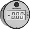
Compressed Air Vacuum Transmitters
 |
Analog Transmitter Output | Digital Switch Output | |||||||||||||||
|---|---|---|---|---|---|---|---|---|---|---|---|---|---|---|---|---|
Analog Signal | No. of | Digital Signal | No. of | Vacuum Range, in. Hg | Max. Continuous Pressure, psi | Max. Short-Term Pressure, psi | Pressure Set Point, in. Hg | Input Voltage, V DC | Ht. | Wd. | Enclosure Rating | Certification | Each | |||
Wire Lead Connection | ||||||||||||||||
1/8 NPT Male Threaded Pipe Connection | ||||||||||||||||
| 1V DC to 5V DC | 1 | PNP | 2 | 0 to 30 | 15 | 72 | 0 to 30 | 12 to 24 | 1 3/16" | 1 3/16" | IP40 | UL Recognized Component, C-UL Recognized Component, CSA Certified, CE Marked | 3859N11 | 000000 | ||
| 4 mA to 20 mA | 1 | PNP | 2 | 0 to 30 | 15 | 72 | 0 to 30 | 12 to 24 | 1 3/16" | 1 3/16" | IP40 | UL Recognized Component, C-UL Recognized Component, CSA Certified, CE Marked | 3859N13 | 00000 | ||
1/4" OD Push-to-Connect Tube Connection | ||||||||||||||||
| 1V DC to 5V DC | 1 | PNP | 2 | 0 to 30 | 15 | 72 | 0 to 30 | 12 to 24 | 1 3/16" | 1 3/16" | IP40 | UL Recognized Component, C-UL Recognized Component, CSA Certified, CE Marked | 3859N12 | 00000 | ||
| 4 mA to 20 mA | 1 | PNP | 2 | 0 to 30 | 15 | 72 | 0 to 30 | 12 to 24 | 1 3/16" | 1 3/16" | IP40 | UL Recognized Component, C-UL Recognized Component, CSA Certified, CE Marked | 3859N14 | 00000 | ||
|
For Panel Cutout | |||||
|---|---|---|---|---|---|
Ht. | Wd. | Mounting Hole Style | Each | ||
| 1 7/32" | 1 7/32" | Straight | 3167K22 | 00000 | |
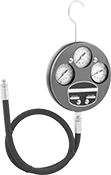
Compression Testers
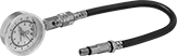 |
Dial Readout |
Check engine compression to maintain top performance.
Add an adapter if you tester does not come with an adapter that matches your engine's spark plug thread size.
Quick-Release Coupler—Testers with a quick-release coupler make it easy to connect and disconnect the gauge and the hose.
Hose | |||||||||||||
|---|---|---|---|---|---|---|---|---|---|---|---|---|---|
Readout Type | Measurement Unit | Pressure Range, psi | Accuracy | Dial Dia. | Lg. | Material | Reinforcement | Includes | Features | Each | |||
For Gasoline Engines | |||||||||||||
| Dial | Pounds per Square Inch, Kilograms per Square Centimeter, Bar, Kilopascals | 0 to 300 | ±2% | 3" | 15" | Rubber | Fiber Braid | M14×1.25 mm Spark Plug Adapter, Replacement Valve Core | Quick-Release Coupler | 6136A24 | 000000 | ||