Filter by
Material


Mount Type
Strike Plate Material
System of Measurement
Door Thickness
Push-to-Close Latch Type
Ball Material
Pull Strength
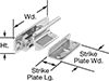
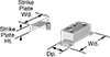
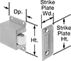
Width
Height
Projection
Strike Plate Height
Export Control Classification Number (ECCN)
DFARS Specialty Metals
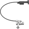
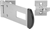
Push-to-Close Latches
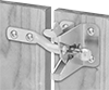
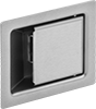
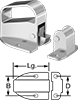
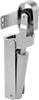
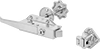
Push-to-Close Latches with Handle
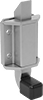
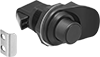
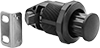
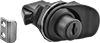
Push-to-Close Latches with Push-Button Release
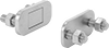
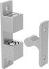
Push-to-Close Latches
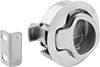
Push-to-Close Latches with Pop-Out Knob
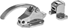
Keyed Push-to-Close Locking Latches with Handle


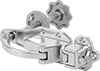
Padlockable Push-to-Close Latches with Handle
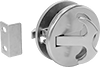
Keyed Push-to-Close Locking Latches

Other Products