


Measure your pipe and fittings to identify their pipe size, thread size, schedule, and thread type. Then, find compatible components.
Medium-Pressure Stainless Steel Butt-Weld Pipe Fittings
Low-Pressure Iron and Steel Butt-Weld Pipe Fittings

Low-Pressure Stainless Steel Butt-Weld Pipe Fittings

 |
Straight Adapter |
304/304L Stainless Steel | 316/316L Stainless Steel | ||||||||
|---|---|---|---|---|---|---|---|---|---|
Pipe Size | Wall Thk. | Flange OD | Construction | Pipe Schedule | Each | Each | |||
| 4 | 0.12" | 6 3/16" | Welded | 10 | 45735K299 | 000000 | 43645K399 | 000000 | |
| 6 | 0.134" | 8 1/2" | Welded | 10 | 45735K312 | 000000 | 43645K154 | 000000 | |
| 8 | 0.148" | 10 5/8" | Welded | 10 | 45735K116 | 000000 | 43645K155 | 000000 | |
| 10 | 0.134" | 12 3/4" | Welded | 10 | 45735K622 | 000000 | ——— | 0 | |
| 12 | 0.156" | 15" | Welded | 10 | 45735K623 | 000000 | ——— | 0 | |
Standard-Wall Plastic Pipe Fittings for Water
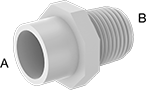 |
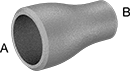
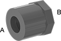
Female × Male |
Pipe Size | |||||||||||
|---|---|---|---|---|---|---|---|---|---|---|---|
(A) | (B) | Pipe Schedule | Body Shape | Material | Color | Max. Pressure @ Temp. | Food Industry Std. | Each | |||
Cement Socket Female × NPT Male | |||||||||||
| 8 | 6 | 40 | Hex | PVC | White | Not Rated | NSF/ANSI 61 | 4880K449 | 0000000 | ||
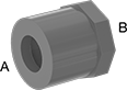
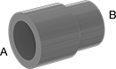
 |  |
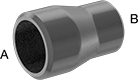
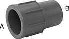
Cement Socket Male × NPT Female | Cement Socket Male × Cement Socket Female |
Pipe Size | |||||||||||
|---|---|---|---|---|---|---|---|---|---|---|---|
(A) | (B) | Pipe Schedule | Body Shape | Material | Color | Max. Pressure @ Temp. | Food Industry Std. | Each | |||
Cement Socket Male × Cement Socket Female | |||||||||||
| 8 | 3 | 40 | Hex | PVC | White | Not Rated | NSF/ANSI 61 | 4880K927 | 000000 | ||
| 8 | 4 | 40 | Hex | PVC | White | Not Rated | NSF/ANSI 61 | 4880K185 | 00000 | ||
| 8 | 6 | 40 | Hex | PVC | White | Not Rated | NSF/ANSI 61 | 4880K186 | 00000 | ||
| 10 | 8 | 40 | Round | PVC | White | Not Rated | NSF/ANSI 61 | 4880K928 | 000000 | ||
 |
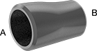
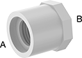
Female × Female |
Pipe Size | ||||||||||
|---|---|---|---|---|---|---|---|---|---|---|
(A) | (B) | Pipe Schedule | Material | Color | Max. Pressure @ Temp. | Food Industry Std. | Each | |||
Cement Socket Female × Cement Socket Female | ||||||||||
| 8 | 2 | 40 | PVC | White | Not Rated | NSF/ANSI 61 | 4880K023 | 0000000 | ||
| 8 | 4 | 40 | PVC | White | Not Rated | NSF/ANSI 61 | 4880K024 | 00000 | ||
| 8 | 6 | 40 | PVC | White | Not Rated | NSF/ANSI 61 | 4880K689 | 00000 | ||
| 10 | 8 | 40 | PVC | White | Not Rated | NSF/ANSI 61 | 4880K911 | 000000 | ||
| 12 | 8 | 40 | PVC | White | Not Rated | NSF/ANSI 61 | 4880K027 | 000000 | ||
 |
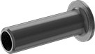
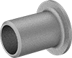
Female |
Thick-Wall Plastic Pipe Fittings for Water
 |
Cement Socket Male × Cement Socket Female |
Pipe Size | |||||||||||
|---|---|---|---|---|---|---|---|---|---|---|---|
(A) | (B) | Pipe Schedule | Body Shape | Material | Color | Max. Pressure @ Temp. | Food Industry Std. | Each | |||
Cement Socket Male × Cement Socket Female | |||||||||||
| 8 | 2 | 80 | Hex | PVC | Dark Gray | Not Rated | NSF/ANSI 61 | 4881K691 | 0000000 | ||
| 8 | 3 | 80 | Hex | PVC | Dark Gray | Not Rated | NSF/ANSI 61 | 4881K658 | 000000 | ||
| 8 | 4 | 80 | Hex | PVC | Dark Gray | Not Rated | NSF/ANSI 61 | 4881K692 | 000000 | ||
| 8 | 6 | 80 | Hex | PVC | Dark Gray | Not Rated | NSF/ANSI 61 | 4881K678 | 00000 | ||
| 10 | 8 | 80 | Hex | PVC | Dark Gray | Not Rated | NSF/ANSI 61 | 4881K694 | 000000 | ||
| 12 | 8 | 80 | Hex | PVC | Dark Gray | Not Rated | NSF/ANSI 61 | 4881K414 | 000000 | ||
 |
Cement Socket Female × Cement Socket Female |
Pipe Size | ||||||||||
|---|---|---|---|---|---|---|---|---|---|---|
(A) | (B) | Pipe Schedule | Material | Color | Max. Pressure @ Temp. | Food Industry Std. | Each | |||
Cement Socket Female × Cement Socket Female | ||||||||||
| 8 | 4 | 80 | PVC | Dark Gray | Not Rated | NSF/ANSI 61 | 4881K755 | 0000000 | ||
| 8 | 6 | 80 | PVC | Dark Gray | Not Rated | NSF/ANSI 61 | 4881K139 | 000000 | ||
| 10 | 8 | 80 | PVC | Dark Gray | Not Rated | NSF/ANSI 61 | 4881K067 | 000000 | ||
| 12 | 8 | 80 | PVC | Dark Gray | Not Rated | NSF/ANSI 61 | 4881K068 | 00000000 | ||
 |
Cement Socket Female × Cement Socket Female |
Pipe Size | ||||||||||
|---|---|---|---|---|---|---|---|---|---|---|
(A) | (B) | Pipe Schedule | Material | Color | Max. Pressure @ Temp. | Food Industry Std. | Each | |||
Cement Socket Female × Cement Socket Female | ||||||||||
| 8 | 6 | 80 | PVC | Dark Gray | Not Rated | NSF/ANSI 61 | 4881K461 | 0000000 | ||
 |
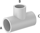
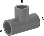
Cement Socket Female x NPT Female x Cement Socket Female |
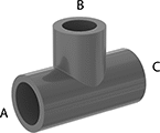 |
Cement Socket Female |
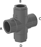 |
Cement Socket Female |
Pipe Size | ||||||||||||
|---|---|---|---|---|---|---|---|---|---|---|---|---|
(A) | (B) | (C) | (D) | Pipe Schedule | Material | Color | Max. Pressure @ Temp. | Food Industry Std. | Each | |||
Cement Socket Female × Cement Socket Female × Cement Socket Female × Cement Socket Female | ||||||||||||
| 8 | 6 | 8 | 6 | 80 | PVC | Dark Gray | Not Rated | NSF/ANSI 61 | 4881K091 | 0000000 | ||
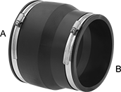
Drain, Waste, and Vent PVC Clamp-On Pipe Fittings for Water
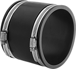 | 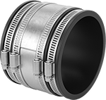 |
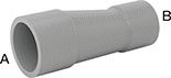
Pipe End × Pipe End | Pipe End × Pipe End—300 Series Stainless Steel Sleeve |
For Pipe Size | For Pipe OD | Material | Max. Pressure @ Temp. | Clamp Material | Sleeve Material | Certification | Each | |||
|---|---|---|---|---|---|---|---|---|---|---|
Clamp-On Female for Pipe Ends × Clamp-On Female for Pipe Ends | ||||||||||
| 8 | 8 5/8" | PVC | 4 psi @ 72° F | 300 Series Stainless Steel | 300 Series Stainless Steel | ICC-ES Listed | 4511K331 | 0000000 | ||
| 8 | 8 5/8" | PVC | 4 psi @ 72° F | 316 Stainless Steel | — | CSA Certified, ICC-ES Listed | 4693K84 | 00000 | ||
 | 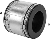 |
Pipe End × Pipe End | Pipe End × Pipe End—300 Series Stainless Steel Sleeve |
For Pipe Size | ||||||||||
|---|---|---|---|---|---|---|---|---|---|---|
(A) | (B) | Material | Max. Pressure @ Temp. | Clamp Material | Sleeve Material | Certification | Each | |||
Clamp-On Female for Pipe Ends × Clamp-On Female for Pipe Ends | ||||||||||
| 8 | 4 | PVC | 4 psi @ 72° F | 300 Series Stainless Steel | — | CSA Certified, ICC-ES Listed | 4511K64 | 000000 | ||
| 8 | 6 | PVC | 4 psi @ 72° F | 300 Series Stainless Steel | — | CSA Certified, ICC-ES Listed | 4511K65 | 00000 | ||
| 8 | 6 | PVC | 4 psi @ 72° F | 300 Series Stainless Steel | 300 Series Stainless Steel | ICC-ES Listed | 4511K421 | 000000 | ||
| 10 | 8 | PVC | 4 psi @ 72° F | 300 Series Stainless Steel | — | CSA Certified, ICC-ES Listed | 4511K66 | 00000 | ||
| 10 | 8 | PVC | 4 psi @ 72° F | 316 Stainless Steel | — | CSA Certified, ICC-ES Listed | 4693K66 | 00000 | ||
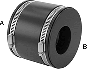 |
Clamp On × Clamp On |
For Pipe Size | ||||||||
|---|---|---|---|---|---|---|---|---|
(A) | (B) | Material | Max. Pressure @ Temp. | Clamp Material | Each | |||
Clamp-On Female for Pipe Ends × Clamp-On Female for Pipe Ends | ||||||||
| 8 | 6 | PVC | 4 psi @ 72° F | 300 Series Stainless Steel | 4511K251 | 0000000 | ||
CPVC Pipe Fittings for Chemicals
 |
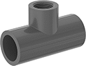
Cement Socket Male × Cement Socket Female, Hex Body |
Pipe Size | |||||||||||
|---|---|---|---|---|---|---|---|---|---|---|---|
(A) | (B) | Pipe Schedule | Body Shape | Material | Color | Max. Pressure @ Temp. | Food Industry Std. | Each | |||
Cement Socket Male × Cement Socket Female | |||||||||||
| 8 | 6 | 80 | Hex | CPVC | Light Gray | Not Rated | NSF/ANSI 61 | 6826K184 | 0000000 | ||
 |
Cement Socket Female × Cement Socket Female |
 |
Cement Socket Female |
Pipe Size | |||||||||||
|---|---|---|---|---|---|---|---|---|---|---|---|
(A) | (B) | (C) | Pipe Schedule | Material | Color | Max. Pressure @ Temp. | Food Industry Std. | Each | |||
Cement Socket Female × Cement Socket Female × Cement Socket Female | |||||||||||
| 8 | 6 | 8 | 80 | CPVC | Light Gray | Not Rated | NSF/ANSI 61 | 6826K325 | 0000000 | ||
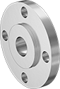
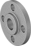
Low-Pressure Stainless Steel Threaded Pipe Flanges
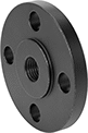
 |  |  |
Reducing Flange | Front | Raised Surface on Back |
Bolt Hole | 304/304L Stainless Steel | |||||||||||||
|---|---|---|---|---|---|---|---|---|---|---|---|---|---|---|
Pipe Size (A) | For Flange Pipe Size (B) | Flanged Connection Surface (B) | Flange OD | For Bolt Dia. | Dia. | No. Of | Bolt Circle Dia. | Pressure Class | Max. Pressure @ Temp. | Max. Steam Pressure @ Temp. | Each | |||
NPT Female | ||||||||||||||
| 6 | 8 | Raised | 13 1/2" | 3/4" | 0.88" | 8 | 11 3/4" | 150 | 230 psi @ 72° F | 150 psi @ 360° F | 44685K246 | 0000000 | ||
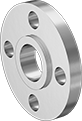
Low-Pressure Iron and Steel Threaded Pipe Flanges
 |  | 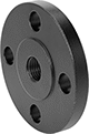 |
Reducing Flange | Raised Surface on Back | Front |
Bolt Hole | |||||||||||||||
|---|---|---|---|---|---|---|---|---|---|---|---|---|---|---|---|
Pipe Size (A) | For Flange Pipe Size (B) | Flanged Connection Surface (B) | Flange OD | For Bolt Dia. | Dia. | No. Of | Bolt Circle Dia. | Pressure Class | Material | Max. Pressure @ Temp. | Max. Steam Pressure @ Temp. | Each | |||
NPT Female | |||||||||||||||
| 6 | 8 | Raised | 13 1/2" | 3/4" | 7/8" | 8 | 11 3/4" | 150 | Steel | 285 psi @ 72° F | 230 psi @ 300° F | 1802N49 | 0000000 | ||
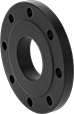
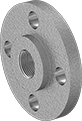
Low-Pressure Stainless Steel Unthreaded Pipe Flanges
|  |  |
Reducing Flange | Slip-On Front | Slip-On Raised Surface on Back |
Bolt Hole | 304/304L Stainless Steel | |||||||||||||
|---|---|---|---|---|---|---|---|---|---|---|---|---|---|---|
Pipe Size (A) | For Flange Pipe Size (B) | Flanged Connection Surface (B) | Flange OD | For Bolt Dia. | Dia. | No. Of | Bolt Circle Dia. | Pressure Class | Max. Pressure @ Temp. | Max. Steam Pressure @ Temp. | Each | |||
Slip-On Weld Female | ||||||||||||||
| 6 | 8 | Raised | 13 1/2" | 3/4" | 7/8" | 8 | 11 3/4" | 150 | 230 psi @ 72° F | 150 psi @ 360° F | 44685K135 | 0000000 | ||
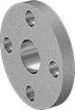
Low-Pressure Iron and Steel Unthreaded Pipe Flanges
 | 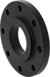 |
Front | Raised Surface on Back |
Bolt Hole | |||||||||||||||
|---|---|---|---|---|---|---|---|---|---|---|---|---|---|---|---|
Pipe Size (A) | For Flange Pipe Size (B) | Flanged Connection Surface (B) | Flange OD | For Bolt Dia. | Dia. | No. Of | Bolt Circle Dia. | Pressure Class | Material | Max. Pressure @ Temp. | Max. Steam Pressure @ Temp. | Each | |||
Slip-On Weld Female | |||||||||||||||
| 6 | 8 | Raised | 13 1/2" | 3/4" | 7/8" | 8 | 11 3/4" | 150 | Steel | 285 psi @ 72° F | 230 psi @ 300° F | 68095K66 | 0000000 | ||
Pipe Expansion Joint Reducers with Flanged Ends
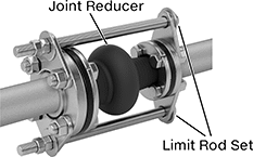 | 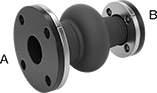 |
Shown Installed on a Flanged Pipe |
Unthreaded Bolt Holes | ||||||||||||||||||||
|---|---|---|---|---|---|---|---|---|---|---|---|---|---|---|---|---|---|---|---|---|
Flange OD | Pipe Size | No. of Bolt Holes | Distance | Bolt Hole Size | ||||||||||||||||
(A) | (B) | (A) | (B) | Lg. | (A) | (B) | Compression | Expansion | Offset | Max. Pressure @ Temp. | Expansion Joint Type | Flange Material | For Use With | Temp. Range, ° F | Max. Vacuum @ Temp. | (A) | (B) | Each | ||
| 13 1/2" | 11" | 8 | 6 | 8" | 8 | 8 | 1 9/16" | 3/4" | 1/2" | 190 psi @ 72° F | Single Bulb | EPDM | Air, Alcohol, Grain Alcohol, Calcium Chloride, Coolant, Grease, Hydraulic Fluid, Water, Sodium Carbonate (Soda Ash) | -20 to 250 | 26 in. Hg @ 72° F | 7/8" | 7/8" | 4983N17 | 000000000 | |
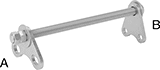 |
For Pipe Size | |||||||
|---|---|---|---|---|---|---|---|
(A) | (B) | Rod Lg. | Includes | Pkg. Qty. | Pkg. | ||
| 8 | 6 | 17" | Four Limit Rod Plates, Two Limit Rods with Nuts | 2 | 4983N175 | 0000000 | |
Low-Pressure Aluminum Unthreaded Pipe Flanges
 |  |  |
Slip-On Weld | Front | Flat Surface on Back |
Bolt Hole | ||||||||||||||
|---|---|---|---|---|---|---|---|---|---|---|---|---|---|---|
Pipe Size (A) | For Flange Pipe Size (B) | Flanged Connection Surface (B) | Flange OD | For Bolt Dia. | Dia. | No. Of | Bolt Circle Dia. | Pressure Class | Material | Max. Pressure @ Temp. | Each | |||
Slip-On Weld Female | ||||||||||||||
| 6 | 8 | Flat | 13 1/2" | 3/4" | 7/8" | 8 | 11 3/4" | 125 | 356 Aluminum | 150 psi @ 72° F | 44705K771 | 0000000 | ||
Low-Pressure Aluminum Threaded Pipe Flanges
 | 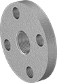 |
Front | Flat Surface on Back |
Bolt Hole | ||||||||||||||
|---|---|---|---|---|---|---|---|---|---|---|---|---|---|---|
Pipe Size (A) | For Flange Pipe Size (B) | Flanged Connection Surface (B) | Flange OD | For Bolt Dia. | Dia. | No. Of | Bolt Circle Dia. | Pressure Class | Material | Max. Pressure @ Temp. | Each | |||
NPT Female | ||||||||||||||
| 6 | 8 | Flat | 13 1/2" | 3/4" | 7/8" | 8 | 11 3/4" | 125 | 356 Aluminum | 150 psi @ 72° F | 44705K742 | 0000000 | ||
