


Filter by
Switching Voltage
Mounting Location
Operation Type


Switch Starting Position
Electrical Connection
Control Current
Wire Connection
Timer Function
Switch Action
U.S.–Mexico–Canada Agreement (USMCA) Qualifying
DFARS Specialty Metals
REACH
Export Control Classification Number (ECCN)
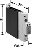
DIN-Rail Mount Solid State Relays
 | 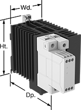 | 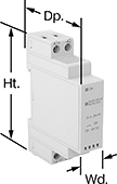 |
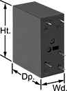
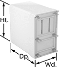
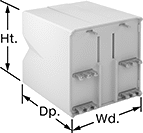
Relay with Integrated Heat Sink | Relay with Integrated Heat Sink and Fan | Relay |
Unlike mechanical relays, these solid state relays have no moving parts, so they require less maintenance and last longer, switch faster, and are quieter. They mount on 35 mm DIN rail (also known as DIN 3) for fast installation. An LED indicator lights up when these relays are connected, so you can quickly confirm that they’re wired correctly. IP20 rated, their terminals are recessed, so they prevent fingers and other objects from touching live circuits.
Integrated Heat Sink—Relays with an integrated heat sink disperse heat to increase the relay’s current rating.
No. of Terminals | Input Voltage | Control Current, mA | Switching Current @ Voltage (Load Type) | Max. Switching Voltage, V AC | Ht. | Wd. | Dp. | Features | Each | |||
|---|---|---|---|---|---|---|---|---|---|---|---|---|
1 Circuit Controlled with 1 Off—SPST-NO | ||||||||||||
Single Phase | ||||||||||||
| 4 | 24V AC, 90V AC, 120V AC, 240V AC, 24V DC, 48V DC, 60V DC, 120V DC, 275V AC | 12 | 5 amp @ 24V AC (Full) 10 amp @ 24V AC (Resistive) 10 amp @ 240V AC | 240 | 4.173" | 0.7" | 2.56" | Integrated Heat Sink, LED Indicator | 8299K34 | 000000 | ||
Circuit Board Relays
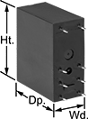 |  |  |  |
8 Terminals | 5 Terminals | 6 Terminals | 14 Terminals |
No. of Terminals | Input Voltage | Control Current, mA | Switching Current @ Voltage | Max. Switching Voltage, V AC | Mechanical Life Cycles | Ht. | Wd. | Dp. | Pin Lg. | Each | |||
|---|---|---|---|---|---|---|---|---|---|---|---|---|---|
Mechanical Operation | |||||||||||||
1 Circuit Controlled with 1 Off or 1 On—SPDT | |||||||||||||
| 5 | 24V AC, 24V DC | 12 | 6 amp @ 240V AC | 250 | 10,000,000 | 1.1" | 0.2" | 0.6" | 0.14" | 8262T21 | 00000 | ||
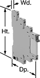
DIN-Rail Mount Interface Relays
2 Circuits Controlled with 2 Off or 2 On—DPDT
 |
With Spring-Clamp Terminals |
With Spring-Clamp Terminals—Relays with spring-clamp terminals connect and disconnect to wires without needing to turn screws. Because there is no screw, these connections have less risk of loosening over time than screw terminals, even when there is vibration.
PLC Output Protection—Relays with PLC output protection prevent voltage spikes created by the relay from damaging the output channel on your programmable logic controller (PLC).
Interface Relays | Replacement Relays | ||||||||||||||
|---|---|---|---|---|---|---|---|---|---|---|---|---|---|---|---|
No. of Terminals | Input Voltage | Control Current, mA | Switching Current @ Voltage | Max. Switching Voltage, V AC | hp @ Switching Voltage | Ht. | Wd. | Dp. | Features | Each | Each | ||||
With Spring-Clamp Terminals | |||||||||||||||
| 8 | 120V AC | 12 | 10 amp @ 240V AC | 250 | 1/3 hp @ 120V AC | 3.9" | 1.2" | 3.3" | LED Indicator, PLC Output Protection | 4144N123 | 000000 | 4144N134 | 000000 | ||
3 Circuits Controlled with 3 Off or 3 On—3PDT
 |
With Screw Terminals |
PLC Output Protection—Relays with PLC output protection prevent voltage spikes created by the relay from damaging the output channel on your programmable logic controller (PLC).
Interface Relays | Replacement Relays | ||||||||||||||
|---|---|---|---|---|---|---|---|---|---|---|---|---|---|---|---|
No. of Terminals | Input Voltage | Control Current, mA | Switching Current @ Voltage | Max. Switching Voltage, V AC | hp @ Switching Voltage | Ht. | Wd. | Dp. | Features | Each | Each | ||||
With Screw Terminals | |||||||||||||||
| 11 | 120V AC | 12 | 10 amp @ 240V AC | 250 | 1/3 hp @ 120V AC | 3.1" | 1.1" | 3.3" | LED Indicator, PLC Output Protection | 4144N116 | 000000 | 4144N131 | 000000 | ||
4 Circuits Controlled with 4 Off or 4 On—4PDT
 |
With Screw Terminals |
PLC Output Protection—Relays with PLC output protection prevent voltage spikes created by the relay from damaging the output channel on your programmable logic controller (PLC).
Interface Relays | Replacement Relays | ||||||||||||||
|---|---|---|---|---|---|---|---|---|---|---|---|---|---|---|---|
No. of Terminals | Input Voltage | Control Current, mA | Switching Current @ Voltage | Max. Switching Voltage, V AC | hp @ Switching Voltage | Ht. | Wd. | Dp. | Features | Each | Each | ||||
With Screw Terminals | |||||||||||||||
| 14 | 120V AC | 12 | 7 amp @ 240V AC | 250 | 1/8 hp @ 120V AC | 3.1" | 1.1" | 3.3" | LED Indicator, PLC Output Protection | 4144N111 | 000000 | 4144N125 | 000000 | ||
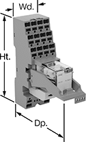
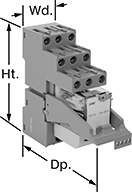
Solid State DIN-Rail Mount Multifunction Interface Timer Relays
 |
Considered solid state because they don’t have any moving parts, these timer relays last longer, switch faster, and are quieter than mechanical relays. They interface between your controller and components to isolate input and output circuits, preventing damage to your components from voltage spikes, amplifying the relay's signal, and reducing signal interference. Use these relays with switching applications, such as small motors and pilot lights. They offer multiple timing functions in one relay. The included relay socket mounts on 35 mm DIN rail (also known as DIN 3 rail) for fast installation. Relays disconnect from the socket for easy replacement.
Timer Relays | Replacement Relays | |||||||||||||||
|---|---|---|---|---|---|---|---|---|---|---|---|---|---|---|---|---|
Timing Range | ||||||||||||||||
No. of Terminals | Input Voltage | Control Current, mA | Timer Relay Function | No. of | Overall | Switching Current @ Voltage | Max. Switching Voltage | Ht. | Wd. | Dp. | Each | Each | ||||
1 Circuit Controlled with 1 Off—SPST-NO | ||||||||||||||||
| 5 | 24V AC, 24V DC | 12 | Delayed Start (Delay on Make) Interval Repeat Cycle | 4 | 0.1 sec. to 6 hr. | 2 amp @ 12V AC to 275V AC, 240V AC | 275V AC | 3 1/2" | 0.2" | 2.8" | 4799T13 | 000000 | 4799T22 | 000000 | ||
| 5 | 24V AC, 24V DC | 12 | Delayed Start (Delay on Make) Interval Repeat Cycle | 4 | 0.1 sec. to 6 hr. | 6 amp @ 2V DC to 33V DC, 24V DC | 33V DC | 3 1/2" | 0.2" | 2.8" | 4799T12 | 00000 | 4799T23 | 00000 | ||
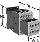
Safety Relays
SIL 3, PLe, Cat. 4 Max. System Safety Rating—DIN-Rail Mount, Surface Mount
 |
Relays that meet SIL 3 are tested for applications with a probability of failure of 0.01% to 0.1% and are used for preventing fires, explosions, or toxic releases.
Relays that meet Cat. 4 withstand circuit surges in electrical applications up to 600V.
Mirror Auxiliary Contacts—Relays with mirror auxiliary contacts have contacts that are normally closed and cannot be open at the same time as a normally open main contact.
Nondetachable Auxiliary Contacts—Relays with nondetachable contacts have auxiliary contacts that won’t separate from the relay if there is shock or vibration.
Self-Monitoring Circuitry—When a failure is detected, relays with self-monitoring circuitry signal the controller to remove power and prevent restarting until the issue is resolved.
hp @ Switching Voltage | |||||||||||||||
|---|---|---|---|---|---|---|---|---|---|---|---|---|---|---|---|
No. of Terminals | Input Voltage, V DC | Control Current, mA | Switching Current @ Voltage | Max. Switching Voltage, V AC | Single Phase | Three Phase | Aux. Contact Switch Starting Position | Ht. | Wd. | Dp. | Features | Each | |||
Screw-Terminal Wire Connection | |||||||||||||||
3 Circuits Controlled with 3 Off—3PST-NO | |||||||||||||||
| 18 | 24 | 12 | 7 amp @ 400V AC | 600 | 1/4 hp @ 120V AC 1 hp @ 240V AC | 2 hp @ 240V AC 3 hp @ 480V AC 5 hp @ 600V AC | 2 Off and 3 On | 2.7" | 1.8" | 4.6" | Inspection Window, Interlocked Opposing Contacts, Mirror Auxiliary Contacts, Nondetachable Auxiliary Contacts, Recessed Terminals, Self-Monitoring Circuitry | 6242N15 | 0000000 | ||
