


Filter by
Switching Voltage
Mounting Location
Horsepower @ Switching Voltage
Operation Type
Control Current


Switch Starting Position
Electrical Connection
Wire Connection


Switch Action
Load Type
Overall Timing
U.S.–Mexico–Canada Agreement (USMCA) Qualifying
DFARS Specialty Metals
Export Control Classification Number (ECCN)
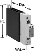
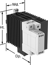
DIN-Rail Mount Solid State Relays
 |  | 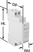 |
Relay with Integrated Heat Sink | Relay with Integrated Heat Sink and Fan | Relay |
Unlike mechanical relays, these solid state relays have no moving parts, so they require less maintenance and last longer, switch faster, and are quieter. They mount on 35 mm DIN rail (also known as DIN 3) for fast installation. An LED indicator lights up when these relays are connected, so you can quickly confirm that they’re wired correctly. IP20 rated, their terminals are recessed, so they prevent fingers and other objects from touching live circuits.
Integrated Heat Sink—Relays with an integrated heat sink disperse heat to increase the relay’s current rating.
Integrated Fan—Relays with an integrated fan are best for applications that generate more heat. The fan automatically turns on to provide additional cooling. When the temperature exceeds 176° F, an alarm sends a signal to an external device, such as a controller or indicating light.
No. of Terminals | Input Voltage | Control Current, mA | Switching Current @ Voltage (Load Type) | Max. Switching Voltage, V AC | hp @ Switching Voltage | Ht. | Wd. | Dp. | Features | Each | |||
|---|---|---|---|---|---|---|---|---|---|---|---|---|---|
2 Circuits Controlled with 2 Off—DPST-NO | |||||||||||||
Three Phase | |||||||||||||
| 8 | 24V AC, 120V AC, 208V AC, 240V AC, 277V AC/24V DC, 48V DC, 60V DC, 120V DC | 2 | 25 amp @ 220V AC (Full) | 242 | 1 1/2 hp @ 115V AC 3 hp @ 230V AC | 4.33" | 2.13" | 3.427" | Integrated Heat Sink, LED Indicator | 7456K81 | 0000000 | ||
| 8 | 24V AC, 120V AC, 208V AC, 240V AC, 277V AC/24V DC, 48V DC, 60V DC, 120V DC | 2 | 25 amp @ 600V AC (Full) | 660 | 5 hp @ 230V AC 10 hp @ 480V AC | 4.33" | 2.13" | 3.427" | Integrated Heat Sink, LED Indicator | 7456K82 | 000000 | ||
| 8 | 24V AC, 120V AC, 208V AC, 240V AC, 277V AC/24V DC, 48V DC, 60V DC, 120V DC | 2 | 40 amp @ 600V AC (Full) | 660 | 5 hp @ 230V AC 10 hp @ 480V AC | 4.33" | 2.84" | 4.66" | Integrated Heat Sink, LED Indicator | 6323T83 | 000000 | ||
| 15 | 24V AC, 120V AC, 208V AC, 240V AC, 277V AC/24V DC, 48V DC, 60V DC, 120V DC | 2 | 75 amp @ 600V AC (Full) | 660 | 10 hp @ 230V AC 20 hp @ 480V AC | 5.55" | 2.84" | 4.679" | Integrated Heat Sink, Integrated Fan, LED Indicator | 6323T85 | 000000 | ||
3 Circuits Controlled with 3 Off—3PST-NO | |||||||||||||
Three Phase | |||||||||||||
| 8 | 24V AC, 120V AC, 208V AC, 240V AC, 277V AC/24V DC, 48V DC, 60V DC, 120V DC | 2 | 20 amp @ 600V AC (Full) | 660 | 3 hp @ 230V AC 7 1/2 hp @ 480V AC | 4.33" | 2.1" | 3.427" | Integrated Heat Sink, LED Indicator | 6323T71 | 000000 | ||
| 8 | 24V AC, 120V AC, 208V AC, 240V AC, 277V AC/24V DC, 48V DC, 60V DC, 120V DC | 2 | 30 amp @ 600V AC (Full) | 660 | 5 hp @ 230V AC 10 hp @ 480V AC | 4.33" | 2.84" | 4.66" | Integrated Heat Sink, LED Indicator | 6323T87 | 000000 | ||
| 15 | 24V AC, 120V AC, 208V AC, 240V AC, 277V AC/24V DC, 48V DC, 60V DC, 120V DC | 2 | 40 amp @ 600V AC (Full) | 660 | 5 hp @ 230V AC 10 hp @ 480V AC | 5.31" | 2.13" | 3.739" | Integrated Heat Sink, Integrated Fan, LED Indicator | 6323T89 | 000000 | ||
| 15 | 24V AC, 120V AC, 208V AC, 240V AC, 277V AC/24V DC, 48V DC, 60V DC, 120V DC | 2 | 65 amp @ 600V AC (Full) | 660 | 10 hp @ 230V AC 20 hp @ 480V AC | 5.55" | 2.84" | 4.679" | Integrated Heat Sink, Integrated Fan, LED Indicator | 6323T92 | 000000 | ||
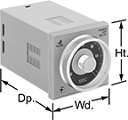
Solid State Versa-Mount Timer Relays
 | 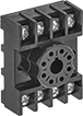 |
Sockets |
Mount these timer relays in a panel cutout or plug them into a relay socket for quick installation. Capable of fast switching, they are solid state and have no moving parts, so they require less maintenance, last longer, and are quieter than mechanical relays. Unlike standard relays that switch on and off immediately, timer relays delay before the circuit stops or starts.
Delayed Off—Delayed off relays let you set how long it takes for the relay to turn off after input voltage is removed. For example, a sensor detects when an item has been placed on a conveyor, triggering the relay to start the conveyor belt and a cooling fan. After the item has moved past another sensor, the input voltage is removed to stop the conveyor, while the cooling fan runs for a set time before shutting off.
Sockets—Relay sockets (sold separately) mount to 35 mm DIN rail (also known as DIN 3 rail) or can be mounted to a flat surface.
Timer Relays | Sockets | |||||||||||||
|---|---|---|---|---|---|---|---|---|---|---|---|---|---|---|
Timing Range | ||||||||||||||
No. of Terminals | Input Voltage | Control Current, mA | No. of | Overall | Switching Current @ Voltage | Ht. | Wd. | Dp. | Each | Each | ||||
Delayed Off | ||||||||||||||
2 Circuits Controlled with 2 Off or 2 On—DPDT | ||||||||||||||
| 8 | 120V AC | 2 | 4 | 0.05 sec. to 12 sec. | 5 amp @ 240V AC | 1.9" | 1.9" | 2.74" | 69695K74 | 0000000 | 7122K19 | 00000 | ||
| 8 | 120V AC | 2 | 4 | 3 sec. to 12 min. | 5 amp @ 240V AC | 1.9" | 1.9" | 2.74" | 69695K73 | 000000 | 7122K19 | 0000 | ||
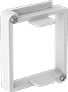 |
Mounting brackets are required to mount relays into a panel cutout.
Mounting Hole | |||||||||||
|---|---|---|---|---|---|---|---|---|---|---|---|
Material | Mounting Location | No. of | Ctr.-to-Ctr. | Dia., mm | Mounting Fasteners Included | Screw Size | Ht. | Wd. | Each | ||
| Polycarbonate | Panel | 2 | 3" | 5 | Yes | M5 | 2.28" | 1.89" | 6963K22 | 000000 | |
Safety Relays
SIL 3, PLe, Cat. 4 Max. System Safety Rating—DIN-Rail Mount, Surface Mount
 |
Relays that meet SIL 3 are tested for applications with a probability of failure of 0.01% to 0.1% and are used for preventing fires, explosions, or toxic releases.
Relays that meet Cat. 4 withstand circuit surges in electrical applications up to 600V.
Mirror Auxiliary Contacts—Relays with mirror auxiliary contacts have contacts that are normally closed and cannot be open at the same time as a normally open main contact.
Nondetachable Auxiliary Contacts—Relays with nondetachable contacts have auxiliary contacts that won’t separate from the relay if there is shock or vibration.
Self-Monitoring Circuitry—When a failure is detected, relays with self-monitoring circuitry signal the controller to remove power and prevent restarting until the issue is resolved.
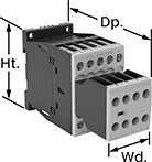
hp @ Switching Voltage | |||||||||||||||
|---|---|---|---|---|---|---|---|---|---|---|---|---|---|---|---|
No. of Terminals | Input Voltage, V AC | Control Current, mA | Switching Current @ Voltage | Max. Switching Voltage, V AC | Single Phase | Three Phase | Aux. Contact Switch Starting Position | Ht. | Wd. | Dp. | Features | Each | |||
Screw-Terminal Wire Connection | |||||||||||||||
3 Circuits Controlled with 3 Off—3PST-NO | |||||||||||||||
| 18 | 120 | 2 | 7 amp @ 400V AC | 600 | 1/4 hp @ 120V AC 1 hp @ 240V AC | 2 hp @ 240V AC 3 hp @ 480V AC 5 hp @ 600V AC | 2 Off and 3 On | 2.7" | 1.8" | 4.6" | Inspection Window, Interlocked Opposing Contacts, Mirror Auxiliary Contacts, Nondetachable Auxiliary Contacts, Recessed Terminals, Self-Monitoring Circuitry | 6242N11 | 0000000 | ||
| 18 | 120 | 2 | 9 amp @ 400V AC | 600 | 1/2 hp @ 120V AC 1 1/2 hp @ 240V AC | 3 hp @ 240V AC 5 hp @ 480V AC 7 1/2 hp @ 600V AC | 2 Off and 3 On | 2.7" | 1.8" | 4.6" | Inspection Window, Interlocked Opposing Contacts, Mirror Auxiliary Contacts, Nondetachable Auxiliary Contacts, Recessed Terminals, Self-Monitoring Circuitry | 6242N12 | 000000 | ||
| 18 | 120 | 2 | 12 amp @ 400V AC | 600 | 1 hp @ 120V AC 2 hp @ 240V AC | 3 hp @ 240V AC 10 hp @ 480V AC 10 hp @ 600V AC | 2 Off and 3 On | 2.7" | 1.8" | 4.6" | Inspection Window, Interlocked Opposing Contacts, Mirror Auxiliary Contacts, Nondetachable Auxiliary Contacts, Recessed Terminals, Self-Monitoring Circuitry | 6242N13 | 000000 | ||
