


Filter by
Product Family
Switching Voltage
Mounting Location
Control Current


Socket Connection
Wire Connection


Operation Type
Electrical Connection

Horsepower @ Switching Voltage
Switch Action
Switch Starting Position
Overall Timing
DFARS Specialty Metals
U.S.–Mexico–Canada Agreement (USMCA) Qualifying
Export Control Classification Number (ECCN)
RoHS
DIN-Rail Mount Interface Relays
1 Circuit Controlled with 1 Off or 1 On—SPDT
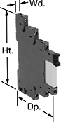 | 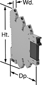 | 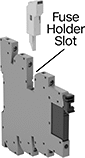 |
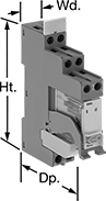
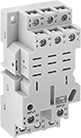
With Screw Terminals | With Spring-Clamp Terminals | Relay with Fuse Holder (Sold Separately) |
With Spring-Clamp Terminals—Relays with spring-clamp terminals connect and disconnect to wires without needing to turn screws. Because there is no screw, these connections have less risk of loosening over time than screw terminals, even when there is vibration.
Fuse Holder Slot—Relays with a fuse holder slot give you the option for additional overload protection. If the current exceeds the fuse’s rating, the fuse will blow and break the circuit. This prevents the relay from overheating, breaking, or causing a fire. The fuse holder is sold separately. You can use these relays without the fuse holder as a standard interface relay.
Interface Relays | Replacement Relays | Fuse Holders | ||||||||||||||
|---|---|---|---|---|---|---|---|---|---|---|---|---|---|---|---|---|
No. of Terminals | Input Voltage | Control Current, mA | Switching Current @ Voltage | Max. Switching Voltage, V AC | Ht. | Wd. | Dp. | Features | Each | Each | Each | |||||
With Screw Terminals | ||||||||||||||||
| 5 | 120V AC, 120V DC | 5 | 6 amp @ 240V AC | 250 | 3.5" | 0.2" | 3" | LED Indicator | 8262T12 | 000000 | 8262T22 | 00000 | ——— | 0 | ||
| 5 | 120V AC, 120V DC | 5 | 6 amp @ 240V AC | 250 | 3.7" | 0.2" | 3.5" | Fuse Holder Slot, LED Indicator | 4144N102 | 00000 | 8262T22 | 0000 | 4144N108 | 00000 | ||
With Spring-Clamp Terminals | ||||||||||||||||
| 5 | 120V AC, 120V DC | 5 | 6 amp @ 240V AC | 250 | 3.7" | 0.2" | 3" | LED Indicator | 4144N17 | 00000 | 8262T22 | 0000 | ——— | 0 | ||
| 5 | 120V AC, 120V DC | 5 | 6 amp @ 240V AC | 250 | 3.7" | 0.2" | 3.5" | Fuse Holder Slot, LED Indicator | 4144N104 | 00000 | 8262T22 | 0000 | 4144N108 | 0000 | ||
2 Circuits Controlled with 2 Off or 2 On—DPDT
 |
With Screw Terminals |
Compact Spade-Terminal Relays
 |  | 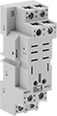 |
11-Terminal Relay Socket | 14-Terminal Relay Socket | 8-Terminal Relay Socket |
Fit these relays where standard spade-terminal relays are too big. You can connect them three ways. Plug them into a socket (sold separately), connect them with quick-disconnect terminals, or solder wires directly to the terminals. An LED indicator shows you the status of the relay, so you know it’s connected and wired correctly.
2 Circuits Controlled and 4 Circuits Controlled—Relays that control 2 or more circuits have a lockable test button, so you can test their function. When you press the button, the relay switches contacts. Use this button when checking a relay for proper function before installing it, or when investigating issues with wired relays.
Sockets with Screw Terminals—Relay sockets mount directly on 35 mm DIN rail (also known as DIN 3 rail) for fast installation. You can also mount them to a flat surface using screws.
Relays | Sockets with Screw Terminals | |||||||||||||||
|---|---|---|---|---|---|---|---|---|---|---|---|---|---|---|---|---|
No. of Terminals | Input Voltage, V AC | Control Current, mA | Switching Current @ Voltage | Max. Switching Voltage, V AC | hp @ Switching Voltage | Ht. | Wd. | Dp. | Quick-Disconnect Tab Wd. | Features | Each | Each | ||||
2 Circuits Controlled with 2 Off or 2 On—DPDT | ||||||||||||||||
Relay-Socket Mount | ||||||||||||||||
| 8 | 240 | 5 | 10 amp @ 120V AC/24V DC | 300 | 1/2 hp @ 120V AC 1 hp @ 277V AC | 1.1" | 0.8" | 1.6" | 0.11" | LED Indicator, Lockable Test Button, Mechanical Flag Indicator | 69585K113 | 000000 | 69585K6 | 00000 | ||
| 8 | 240 | 5 | 15 amp @ 120V AC 12 amp @ 24V DC | 300 | 1/2 hp @ 120V AC 1 hp @ 277V AC | 1.1" | 0.9" | 1.6" | 0.187" | LED Indicator, Lockable Test Button, Mechanical Flag Indicator | 69585K59 | 00000 | 69585K1 | 0000 | ||
4 Circuits Controlled with 4 Off or 4 On—4PDT | ||||||||||||||||
Relay-Socket Mount | ||||||||||||||||
| 14 | 240 | 5 | 8 amp @ 120V AC/24V DC | 300 | 1/2 hp @ 120V AC 1 hp @ 277V AC | 1.1" | 0.9" | 1.6" | 0.11" | LED Indicator, Lockable Test Button, Mechanical Flag Indicator | 69585K123 | 0000 | 69585K6 | 0000 | ||
High-Starting-Current DIN-Rail Mount Timer Relays
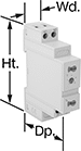 |
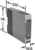
Reduce voltage fluctuations and stress on shafts and bearings when starting up three-phase motors. These timer relays start with motor contacts in a star configuration, then switch to a delta configuration after a set delay. Since star configuration takes less voltage to start than delta, these relays prevent voltage dips that often happen when a motor starts and are gentler on mechanical parts. Mount these relays directly to 35 mm DIN rail (also known as DIN 3 rail) for quick installation.
Timing Range | ||||||||||||||
|---|---|---|---|---|---|---|---|---|---|---|---|---|---|---|
No. of Terminals | Input Voltage | Control Current, mA | Timer Relay Function | No. of | Overall | Switching Current @ Voltage | Max. Switching Voltage, V AC | Ht. | Wd. | Dp. | Each | |||
2 Circuits Controlled with 2 Off—DPST-NO | ||||||||||||||
| 5 | 24V AC, 48V AC, 120V AC, 240V AC, 24V DC, 30V DC, 48V DC, 60V DC, 120V DC, 240V DC | 5 | Star-to-Delta | 6 | 0.1 sec. to 20 min. | 6 amp @ 12V AC to 250V AC, 240V AC | 250 | 3.4" | 0.7" | 2.4" | 8474N11 | 000000 | ||
Safety Relays
SIL 3, PLe Max. System Safety Rating—DIN-Rail Mount
 |
Relays that meet SIL 3 are tested for applications with a probability of failure of 0.01% to 0.1% and are used for preventing fires, explosions, or toxic releases.
Mirror Auxiliary Contacts—Relays with mirror auxiliary contacts have contacts that are normally closed and cannot be open at the same time as a normally open main contact.
Nondetachable Auxiliary Contacts—Relays with nondetachable contacts have auxiliary contacts that won’t separate from the relay if there is shock or vibration.
Self-Monitoring Circuitry—When a failure is detected, relays with self-monitoring circuitry signal the controller to remove power and prevent restarting until the issue is resolved.
No. of Terminals | Input Voltage | Control Current, mA | Switching Current @ Voltage | Max. Switching Voltage, V AC | Aux. Contact Switch Starting Position | Ht. | Wd. | Dp. | Features | Each | |||
|---|---|---|---|---|---|---|---|---|---|---|---|---|---|
Spring-Clamp-Terminal Wire Connection | |||||||||||||
3 Circuits Controlled with 3 Off—3PST-NO | |||||||||||||
| 18 | 24V AC, 24V DC | 5 | 5 amp @ 120V AC | 230 | 1 On | 3.9" | 0.9" | 4.8" | Interlocked Opposing Contacts, LED Indicator, Mirror Auxiliary Contacts, Nondetachable Auxiliary Contacts, Recessed Terminals, Self-Monitoring Circuitry | 6242N122 | 0000000 | ||
SIL 3, PLe, Cat. 4 Max. System Safety Rating—DIN-Rail Mount, Surface Mount
 |
Relays that meet SIL 3 are tested for applications with a probability of failure of 0.01% to 0.1% and are used for preventing fires, explosions, or toxic releases.
Relays that meet Cat. 4 withstand circuit surges in electrical applications up to 600V.
Mirror Auxiliary Contacts—Relays with mirror auxiliary contacts have contacts that are normally closed and cannot be open at the same time as a normally open main contact.
Nondetachable Auxiliary Contacts—Relays with nondetachable contacts have auxiliary contacts that won’t separate from the relay if there is shock or vibration.
Self-Monitoring Circuitry—When a failure is detected, relays with self-monitoring circuitry signal the controller to remove power and prevent restarting until the issue is resolved.
hp @ Switching Voltage | |||||||||||||||
|---|---|---|---|---|---|---|---|---|---|---|---|---|---|---|---|
No. of Terminals | Input Voltage, V AC | Control Current, mA | Switching Current @ Voltage | Max. Switching Voltage, V AC | Single Phase | Three Phase | Aux. Contact Switch Starting Position | Ht. | Wd. | Dp. | Features | Each | |||
Screw-Terminal Wire Connection | |||||||||||||||
3 Circuits Controlled with 3 Off—3PST-NO | |||||||||||||||
| 18 | 120 | 5 | 18 amp @ 400V AC | 600 | 2 hp @ 120V AC 3 hp @ 240V AC | 5 hp @ 240V AC 10 hp @ 480V AC 15 hp @ 600V AC | 2 Off and 3 On | 3.4" | 1.8" | 5.5" | Inspection Window, Interlocked Opposing Contacts, Mirror Auxiliary Contacts, Nondetachable Auxiliary Contacts, Recessed Terminals, Self-Monitoring Circuitry | 6242N14 | 0000000 | ||
| 18 | 120 | 5 | 25 amp @ 400V AC | 600 | 2 hp @ 120V AC 5 hp @ 240V AC | 10 hp @ 240V AC 15 hp @ 480V AC 20 hp @ 600V AC | 2 Off and 3 On | 3.4" | 1.8" | 5.5" | Inspection Window, Interlocked Opposing Contacts, Mirror Auxiliary Contacts, Nondetachable Auxiliary Contacts, Recessed Terminals, Self-Monitoring Circuitry | 6242N19 | 000000 | ||
