


Filter by
System of Measurement
Mounting Location
Timer Function
Switch Starting Position
Electrical Connection


Timing Adjustment Style
Operation Type
Mechanical Life Cycles
Control Current
Horsepower @ Switching Voltage
Wire Connection

Overall Timing
Socket Connection
Certification
U.S.–Mexico–Canada Agreement (USMCA) Qualifying
DFARS Specialty Metals
Export Control Classification Number (ECCN)
RoHS
Compact Spade-Terminal Relays
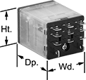 | 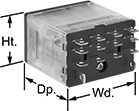 | 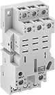 |
11-Terminal Relay | 14-Terminal Relay | 11-Terminal Relay Socket |
 | 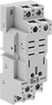 | |
14-Terminal Relay Socket | 8-Terminal Relay Socket |
Fit these relays where standard spade-terminal relays are too big. You can connect them three ways. Plug them into a socket (sold separately), connect them with quick-disconnect terminals, or solder wires directly to the terminals. An LED indicator shows you the status of the relay, so you know it’s connected and wired correctly.
3 Circuits Controlled and 4 Circuits Controlled—Relays that control 2 or more circuits have a lockable test button, so you can test their function. When you press the button, the relay switches contacts. Use this button when checking a relay for proper function before installing it, or when investigating issues with wired relays.
Sockets with Screw Terminals—Relay sockets mount directly on 35 mm DIN rail (also known as DIN 3 rail) for fast installation. You can also mount them to a flat surface using screws.
Relays | Sockets with Screw Terminals | |||||||||||||||
|---|---|---|---|---|---|---|---|---|---|---|---|---|---|---|---|---|
No. of Terminals | Input Voltage | Control Current, mA | Switching Current @ Voltage | Max. Switching Voltage, V AC | hp @ Switching Voltage | Ht. | Wd. | Dp. | Quick-Disconnect Tab Wd. | Features | Each | Each | ||||
3 Circuits Controlled with 3 Off or 3 On—3PDT | ||||||||||||||||
Relay-Socket Mount | ||||||||||||||||
| 11 | 240V AC | 6 | 15 amp @ 120V AC 12 amp @ 24V DC | 300 | 1/2 hp @ 120V AC 1 hp @ 277V AC | 1.1" | 1.2" | 1.6" | 0.187" | LED Indicator, Lockable Test Button, Mechanical Flag Indicator | 69585K71 | 000000 | 69585K2 | 000000 | ||
4 Circuits Controlled with 4 Off or 4 On—4PDT | ||||||||||||||||
Relay-Socket Mount | ||||||||||||||||
| 14 | 24V DC | 6 | 15 amp @ 120V AC 12 amp @ 24V DC | 300 | 1/2 hp @ 120V AC 1 hp @ 277V AC | 1.1" | 1.6" | 1.6" | 0.187" | LED Indicator, Lockable Test Button, Mechanical Flag Indicator | 69585K96 | 00000 | 69585K3 | 00000 | ||
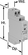
DIN-Rail Mount Multifunction Timer Relays
Timer Relays with Delayed, Interval, Switch On, and Repeat Cycles
 |
1 Circuit Controlled |
Timing Range | ||||||||||||||
|---|---|---|---|---|---|---|---|---|---|---|---|---|---|---|
No. of Terminals | Input Voltage | Control Current, mA | Timer Relay Function | No. of | Overall | Switching Current @ Voltage | Max. Switching Voltage, V AC | Ht. | Wd. | Dp. | Each | |||
1 Circuit Controlled with 1 Off or 1 On—SPDT | ||||||||||||||
| 8 | 12V AC, 24V AC, 48V AC, 120V AC, 240V AC, 12V DC, 24V DC, 48V DC, 60V DC, 120V DC, 240V DC | 6 | Delayed Start (Delay on Make) Delayed Switch Off (Delay on Break) Delayed Switch-On with Delayed Switch-Off Delayed Pulse Interval Interval Switch-Off Switch on (Single Shot) Repeat Cycle Start-Off Repeat Cycle Switch Fixed On/Off | 8 | 0.1 sec. to 10 day | 8 amp @ 240V AC | 250 | 4.1" | 0.7" | 2.6" | 6964K102 | 000000 | ||
