


Filter by
Product Family
Switching Voltage
Mounting Location
Operation Type
Socket Connection
Wire Connection

Horsepower @ Switching Voltage
Switch Starting Position


Timing Adjustment Style


Timer Function
Switch Action
DFARS Specialty Metals
Export Control Classification Number (ECCN)
Control Current
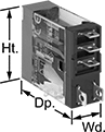
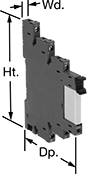
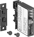
Thin Spade-Terminal Relays
 |  |  |  |
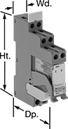
5-Terminal Relay | 8-Terminal Relay | Sockets with Spring-Clamp Terminals | Sockets with Screw Terminals |
Relays | Sockets with Screw Terminals | Sockets with Spring-Clamp Terminals | |||||||||||||||
|---|---|---|---|---|---|---|---|---|---|---|---|---|---|---|---|---|---|
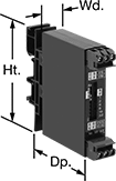
No. of Terminals | Input Voltage, V AC | Control Current, mA | Switching Current @ Voltage | Max. Switching Voltage, V AC | hp @ Switching Voltage | Ht. | Wd. | Dp. | Quick-Disconnect Tab Wd. | Each | Each | Each | |||||
1 Circuit Controlled with 1 Off or 1 On—SPDT | |||||||||||||||||
Relay-Socket Mount | |||||||||||||||||
| 5 | 120 | 8 | 10 amp @ 120V AC/24V DC | 380 | 1/3 hp @ 120V AC | 1.1" | 0.5" | 1.4" | 0.187" | 7098K12 | 000000 | 7098K21 | 00000 | 7098K23 | 00000 | ||
2 Circuits Controlled with 2 Off or 2 On—DPDT | |||||||||||||||||
Relay-Socket Mount | |||||||||||||||||
| 8 | 120 | 8 | 5 amp @ 120V AC/24V DC | 380 | 1/6 hp @ 120V AC | 1.1" | 0.5" | 1.4" | 0.098" | 7098K15 | 00000 | 7098K22 | 00000 | 7098K24 | 00000 | ||
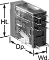
DIN-Rail Mount Interface Relays
1 Circuit Controlled with 1 Off or 1 On—SPDT
 |
With Screw Terminals |
PLC Output Protection—Relays with PLC output protection prevent voltage spikes created by the relay from damaging the output channel on your programmable logic controller (PLC).
Interface Relays | Replacement Relays | ||||||||||||||
|---|---|---|---|---|---|---|---|---|---|---|---|---|---|---|---|
No. of Terminals | Input Voltage | Control Current, mA | Switching Current @ Voltage | Max. Switching Voltage, V AC | hp @ Switching Voltage | Ht. | Wd. | Dp. | Features | Each | Each | ||||
With Screw Terminals | |||||||||||||||
| 5 | 120V AC | 8 | 16 amp @ 240V AC | 250 | 1/3 hp @ 120V AC | 3.3" | 0.6" | 2.7" | LED Indicator, PLC Output Protection | 7098K42 | 000000 | 7098K62 | 000000 | ||
2 Circuits Controlled with 2 Off or 2 On—DPDT
 |
With Screw Terminals |
PLC Output Protection—Relays with PLC output protection prevent voltage spikes created by the relay from damaging the output channel on your programmable logic controller (PLC).
Interface Relays | Replacement Relays | ||||||||||||||
|---|---|---|---|---|---|---|---|---|---|---|---|---|---|---|---|
No. of Terminals | Input Voltage | Control Current, mA | Switching Current @ Voltage | Max. Switching Voltage, V AC | hp @ Switching Voltage | Ht. | Wd. | Dp. | Features | Each | Each | ||||
With Screw Terminals | |||||||||||||||
| 8 | 120V AC | 8 | 8 amp @ 240V AC | 250 | 1/4 hp @ 120V AC | 3.3" | 0.6" | 2.7" | LED Indicator, PLC Output Protection | 7098K45 | 000000 | 7098K65 | 000000 | ||
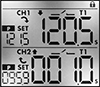
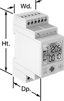
Dual-Channel DIN-Rail Mount Multifunction Timer Relays
 |  |
Timing Range | |||||||||||||||
|---|---|---|---|---|---|---|---|---|---|---|---|---|---|---|---|
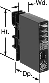
No. of Terminals | Input Voltage | Control Current, mA | Timer Relay Function | No. of | Overall | Switching Current @ Voltage | Max. Switching Voltage, V AC | Ht. | Wd. | Dp. | Features | Each | |||
2 Circuits Controlled with 2 Off and 2 On—DPDT | |||||||||||||||
| 12 | 12V AC, 24V AC, 12V DC, 24V DC | 8 | Manual Switch Control Fixed On/Off Switch on (Single Shot) Delayed Start (Delay on Make) Delayed Switch Off (Delay on Break) Delayed Switch-On with Delayed Switch-Off Interval Repeat Cycle Asymmetrical Repeat Cycle Switch-On Asymmetrical Repeat Cycle | 30 | 0.1 sec. to 9,999 hr. | 16 amp @ 240V AC | 240 | 3.4" | 1.4" | 2.2" | 2 Individually Programmable Timers, LCD Screen, Proximity Sensor Compatability (PNP and NPN) | 7105N11 | 0000000 | ||
Solid State DIN-Rail Mount Multifunction Timer Relays
 |  |  | 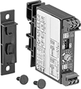 |
Relays with 1 Circuit Controlled, DIP Switches, and Quick-Disconnect Terminals | Relays with 1 Circuit Controlled, DIP Switches, and Screw Terminals | Relays with 1 Circuit Controlled, Knob, and Quick-Disconnect Terminals | Relays with 1 Circuit Controlled, Knob, and Screw Terminals |
Timing Range | |||||||||||||||
|---|---|---|---|---|---|---|---|---|---|---|---|---|---|---|---|
No. of Terminals | Input Voltage | Control Current, mA | Timer Relay Function | No. of | Overall | Switching Current @ Voltage | Max. Switching Voltage, V AC | Ht. | Wd. | Dp. | Wire Connection | Each | |||
Timing-Adjustment DIP Switch | |||||||||||||||
1 Circuit Controlled with 1 Off—SPST-NO | |||||||||||||||
| 4 | 24V AC, 48V AC, 120V AC, 240V AC | 8 | Delayed Start (Delay on Make) Interval Switch on (Single Shot) Delayed Switch Off (Delay on Break) Repeat Cycle | 4 | 0.1 sec. to 63 min. | 0.7 amp @ 240V AC | 240 | 3" | 0.7" | 2.4" | Quick-Disconnect Terminal | 7399K25 | 0000000 | ||
| 4 | 9V DC, 12V DC, 24V DC, 48V DC, 60V DC, 110V DC | 8 | Delayed Start (Delay on Make) Interval Switch on (Single Shot) Delayed Switch Off (Delay on Break) Repeat Cycle | 4 | 0.1 sec. to 63 min. | 0.7 amp @ 240V AC | 240 | 3" | 0.7" | 2.4" | Quick-Disconnect Terminal | 7399K26 | 000000 | ||
| 6 | 9V DC, 12V DC, 24V DC, 48V DC, 60V DC, 110V DC | 8 | Delayed Start (Delay on Make) Interval Switch on (Single Shot) Delayed Switch Off (Delay on Break) Repeat Cycle | 4 | 0.1 sec. to 63 min. | 0.7 amp @ 240V AC | 240 | 3" | 0.7" | 2.4" | Screw Terminal | 7399K28 | 000000 | ||
Timing-Adjustment Knob | |||||||||||||||
1 Circuit Controlled with 1 Off—SPST-NO | |||||||||||||||
| 4 | 24V AC, 48V AC, 120V AC, 240V AC | 8 | Delayed Start (Delay on Make) Interval Switch on (Single Shot) Delayed Switch Off (Delay on Break) Repeat Cycle | 4 | 0.1 sec. to 100 min. | 0.7 amp @ 240V AC | 240 | 3" | 0.7" | 2.4" | Quick-Disconnect Terminal | 7399K21 | 000000 | ||
| 4 | 9V DC, 12V DC, 24V DC, 48V DC, 60V DC, 110V DC | 8 | Delayed Start (Delay on Make) Interval Switch on (Single Shot) Delayed Switch Off (Delay on Break) Repeat Cycle | 4 | 0.1 sec. to 100 min. | 0.7 amp @ 240V AC | 240 | 3" | 0.7" | 2.4" | Quick-Disconnect Terminal | 7399K22 | 000000 | ||
| 6 | 24V AC, 48V AC, 120V AC, 240V AC | 8 | Delayed Start (Delay on Make) Interval Switch on (Single Shot) Delayed Switch Off (Delay on Break) Repeat Cycle | 4 | 0.1 sec. to 100 min. | 0.7 amp @ 240V AC | 240 | 3" | 0.7" | 2.4" | Screw Terminal | 7399K23 | 000000 | ||
| 6 | 9V DC, 12V DC, 24V DC, 48V DC, 60V DC, 110V DC | 8 | Delayed Start (Delay on Make) Interval Switch on (Single Shot) Delayed Switch Off (Delay on Break) Repeat Cycle | 4 | 0.1 sec. to 100 min. | 0.7 amp @ 240V AC | 240 | 3" | 0.7" | 2.4" | Screw Terminal | 7399K24 | 000000 | ||
Multifunction Timer Relays
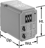 | 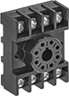 |
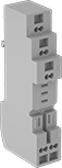
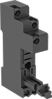
Relay Socket Mounting Location | Sockets |
Get a variety of timing functions in a single relay. All relays plug into relay sockets (sold separately) for fast installation and replacement.
Sockets—Relay sockets (sold separately) mount to 35 mm DIN rail (also known as DIN 3 rail) or can be mounted to a flat surface.
Timer Relays | Sockets | |||||||||||||||
|---|---|---|---|---|---|---|---|---|---|---|---|---|---|---|---|---|
Timing Range | ||||||||||||||||
No. of Terminals | Input Voltage | Control Current, mA | Timer Relay Function | No. of | Overall | Switching Current @ Voltage | Max. Switching Voltage, V AC | Ht. | Wd. | Dp. | Each | Each | ||||
2 Circuits Controlled with 2 Off or 2 On—DPDT | ||||||||||||||||
Relay-Socket Mount | ||||||||||||||||
| 11 | 240V AC | 8 | Delayed Start (Delay on Make) Interval Switch on (Single Shot) Delayed Switch Off (Delay on Break) Repeat Cycle | 5 | 0.05 sec. to 999 min. | 10 amp @ 240V AC | 240 | 2.4" | 1.8" | 3.7" | 6964K13 | 0000000 | 7122K21 | 00000 | ||
