


Filter by
Input Voltage
Timer Function
Mounting Location
Switching Voltage
Overall Timing
Switch Starting Position
Timing Adjustment Style


Wire Connection
Operation Type
Electrical Connection


Certification
Socket Connection
Export Control Classification Number (ECCN)
DFARS Specialty Metals
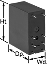
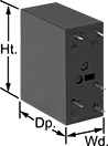
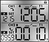
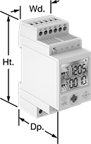
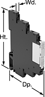
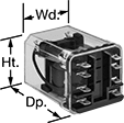
DIN-Rail Mount Multifunction Timer Relays
Timer Relays with Delayed, Interval, Switch On, and Repeat Cycles
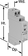 |
1 Circuit Controlled |
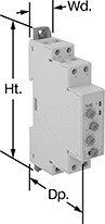 |
2 Circuits Controlled |
Timer relays with delayed, interval, switch-on, and repeat cycles have a broad range of applications. Use them to precisely control machines such as conveyors, lighting systems, and electric motors.
Delayed Start (Delay on Make) Timer—This function allows you to set how long it takes for the relay to turn on after input voltage is applied. For example, a drill starts pumping lubricant immediately, but it does not start rotating until the set time has elapsed.
Delayed Switch Off (Delay on Break) Timer—This function uses a switch instead of input voltage. When the switch is turned off, the relay remains on for a programmed amount of time before turning off. For example, a projector’s light is turned off with a switch, but its cooling fan continues to run for a set time.
Delayed Switch-On with Delayed Switch-Off Timer—This function uses a switch instead of input voltage. It allows you to set how long the relay takes to turn on after a switch is turned on, and how long it will stay on after the switch is turned off. For example, a furnace turns on, but the fan doesn’t start pushing air through the vents until it has been heated. When the furnace turns off, the fan keeps blowing to circulate all the hot air.
Delayed-Pulse Timer—This function uses input voltage to turn on the relay for a brief period after a preset time. For example, a light flashes a few seconds after a door closes.
Interval Timer—This function uses input voltage to turn on the relay for a programmed amount of time. For example, when a part moving down a conveyor reaches a certain location, a cleaning spray comes on for a set time.
Interval Switch-Off Timer—This function requires a switch to activate the relay, which stays off for the programmed amount of time. For example, lights in a storage room are turned on with a switch and stay on for a set time before turning off.
Switch on (Single Shot) Timer—This function requires a switch to activate the relay, which stays on for the programmed amount of time. For example, lights in a storage room are turned on with a switch and stay on for a set time before turning off.
Repeat-Cycle Timer—This function starts with an on cycle and then alternates between an on cycle and off cycle of equal durations until input voltage is removed. A common example would be a flashing light.
Start-Off Repeat Cycle Timer—This function starts with an off cycle and alternates between an on cycle and off cycle of equal durations until input voltage is removed. A common example would be a flashing light.
Switch Fixed On/Off Timer—This function requires a switch to activate the timing function instead of the input voltage (which is applied the entire time). It keeps the relay on whenever the switch is closed; it will only turn off if the switch is open.
Timing Range | ||||||||||||||
|---|---|---|---|---|---|---|---|---|---|---|---|---|---|---|
No. of Terminals | Input Voltage | Control Current, mA | Timer Relay Function | No. of | Overall | Switching Current @ Voltage | Max. Switching Voltage, V AC | Ht. | Wd. | Dp. | Each | |||
1 Circuit Controlled with 1 Off or 1 On—SPDT | ||||||||||||||
| 6 | 12V AC, 24V AC, 48V AC, 120V AC, 240V AC, 12V DC, 24V DC, 48V DC, 60V DC, 120V DC, 240V DC | 7 | Delayed Start (Delay on Make) Delayed Switch Off (Delay on Break) Delayed Switch-On with Delayed Switch-Off Interval Switch on (Single Shot) Repeat Cycle | 6 | 0.1 sec. to 24 hr. | 16 amp @ 240V AC | 250 | 3.5" | 0.7" | 2.4" | 6964K4 | 000000 | ||
| 8 | 12V AC, 24V AC, 48V AC, 120V AC, 240V AC, 12V DC, 24V DC, 48V DC, 60V DC, 120V DC, 240V DC | 6 | Delayed Start (Delay on Make) Delayed Switch Off (Delay on Break) Delayed Switch-On with Delayed Switch-Off Delayed Pulse Interval Interval Switch-Off Switch on (Single Shot) Repeat Cycle Start-Off Repeat Cycle Switch Fixed On/Off | 8 | 0.1 sec. to 10 day | 8 amp @ 240V AC | 250 | 4.1" | 0.7" | 2.6" | 6964K102 | 00000 | ||
2 Circuits Controlled with 2 Off or 2 On—DPDT | ||||||||||||||
| 8 | 12V AC, 24V AC, 48V AC, 120V AC, 240V AC, 12V DC, 24V DC, 48V DC, 60V DC, 120V DC, 240V DC | 7 | Delayed Start (Delay on Make) Delayed Switch Off (Delay on Break) Delayed Switch-On with Delayed Switch-Off Delayed Pulse Interval Interval Switch-Off Switch on (Single Shot) Repeat Cycle Start-Off Repeat Cycle Switch Fixed On/Off | 8 | 0.1 sec. to 10 day | 8 amp @ 240V AC | 250 | 4.1" | 0.7" | 2.6" | 6964K103 | 000000 | ||
Timer Relays with Asymmetrical Repeat Cycles
|
1 Circuit Controlled |
Use timer relays with asymmetrical repeat cycles when your repeat cycles have different on- and off-cycle durations.
Asymmetrical-Repeat-Cycle Timer—This function switches the relay on and alternates between different durations of on and off for as long as input voltage is applied. For example, a sprinkler system sprays in short bursts followed by longer rest periods, on and off until input voltage is removed.
Switch-On Asymmetrical Repeat Cycle Timer—This function switches the relay on and alternates between different durations of on and off for as long as input voltage is applied. It requires a switch to activate the timing function instead of the input voltage that’s being applied the entire time. You could use this function to turn on an electric motor for a short period and then turn it off for a longer rest period, repeating that pattern until the switch is turned off.
Timing Range | ||||||||||||||
|---|---|---|---|---|---|---|---|---|---|---|---|---|---|---|
No. of Terminals | Input Voltage | Control Current, mA | Timer Relay Function | No. of | Overall | Switching Current @ Voltage | Max. Switching Voltage, V AC | Ht. | Wd. | Dp. | Each | |||
1 Circuit Controlled with 1 Off or 1 On—SPDT | ||||||||||||||
| 6 | 12V AC, 24V AC, 48V AC, 120V AC, 240V AC, 12V DC, 24V DC, 48V DC, 60V DC, 120V DC, 240V DC | 7 | Asymmetrical Repeat Cycle Switch-On Asymmetrical Repeat Cycle | 6 | 0.1 sec. to 24 hr. | 16 amp @ 240V AC | 250 | 3.5" | 0.7" | 2.4" | 6964K17 | 000000 | ||
DIN-Rail Mount Interface Relays
1 Circuit Controlled with 1 Off or 1 On—SPDT
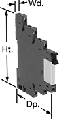 | 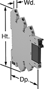 |
With Screw Terminals | With Spring-Clamp Terminals |
Interface Relays | Replacement Relays | |||||||||||||
|---|---|---|---|---|---|---|---|---|---|---|---|---|---|---|
No. of Terminals | Input Voltage | Control Current, mA | Switching Current @ Voltage | Max. Switching Voltage, V AC | Ht. | Wd. | Dp. | Features | Each | Each | ||||
With Screw Terminals | ||||||||||||||
| 5 | 12V AC, 12V DC | 16 | 6 amp @ 240V AC | 250 | 3.5" | 0.2" | 3" | LED Indicator | 8262T14 | 000000 | 8262T15 | 00000 | ||
With Spring-Clamp Terminals | ||||||||||||||
| 5 | 12V AC, 12V DC | 16 | 6 amp @ 240V AC | 250 | 3.7" | 0.2" | 3" | LED Indicator | 4144N15 | 00000 | 8262T15 | 0000 | ||
Circuit Board Relays
 |  |  |  |
8 Terminals | 5 Terminals | 6 Terminals | 14 Terminals |
No. of Terminals | Input Voltage | Control Current, mA | Switching Current @ Voltage | Max. Switching Voltage, V AC | Mechanical Life Cycles | Ht. | Wd. | Dp. | Pin Lg. | Each | |||
|---|---|---|---|---|---|---|---|---|---|---|---|---|---|
Mechanical Operation | |||||||||||||
1 Circuit Controlled with 1 Off or 1 On—SPDT | |||||||||||||
| 5 | 12V AC, 12V DC | 14 | 6 amp @ 240V AC | 250 | 10,000,000 | 1.1" | 0.2" | 0.6" | 0.14" | 8262T15 | 00000 | ||
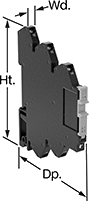
Dual-Channel DIN-Rail Mount Multifunction Timer Relays
 |  |
Timing Range | |||||||||||||||
|---|---|---|---|---|---|---|---|---|---|---|---|---|---|---|---|
No. of Terminals | Input Voltage | Control Current, mA | Timer Relay Function | No. of | Overall | Switching Current @ Voltage | Max. Switching Voltage, V AC | Ht. | Wd. | Dp. | Features | Each | |||
2 Circuits Controlled with 2 Off and 2 On—DPDT | |||||||||||||||
| 12 | 12V AC, 24V AC, 12V DC, 24V DC | 8 | Manual Switch Control Fixed On/Off Switch on (Single Shot) Delayed Start (Delay on Make) Delayed Switch Off (Delay on Break) Delayed Switch-On with Delayed Switch-Off Interval Repeat Cycle Asymmetrical Repeat Cycle Switch-On Asymmetrical Repeat Cycle | 30 | 0.1 sec. to 9,999 hr. | 16 amp @ 240V AC | 240 | 3.4" | 1.4" | 2.2" | 2 Individually Programmable Timers, LCD Screen, Proximity Sensor Compatability (PNP and NPN) | 7105N11 | 0000000 | ||
Circular-Pin Relays
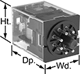 | 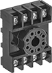 | 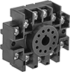 |
8-Terminal Relay (2 Circuits Controlled) | Relay Socket for 8-Terminal Relay | Relay Socket for 11-Terminal Socket |
The circular pin terminals plug into relay sockets for easy installation. Also known as ice cube relays.
Lockable Test Button—Relays with a lockable test button allow you to test whether a relay is working without an electrical signal. They’re helpful for testing relays before you install them, or for checking that installed relays are working properly.
Horsepower @ Switching Voltage—Relays rated for horsepower (hp) are built to handle tough, repetitive-use applications.
Sockets with Screw Terminals—Relay sockets (sold separately) mount to 35 mm DIN rail (also known as DIN 3 rail) or can be mounted to a flat surface.
Relays | Sockets with Screw Terminals | ||||||||||||||
|---|---|---|---|---|---|---|---|---|---|---|---|---|---|---|---|
No. of Terminals | Input Voltage, V AC | Control Current, mA | Switching Current @ Voltage | Max. Switching Voltage, V AC | hp @ Switching Voltage | Ht. | Wd. | Dp. | Features | Each | Each | ||||
2 Circuits Controlled with 2 Off or 2 On—DPDT | |||||||||||||||
Relay-Socket Mount | |||||||||||||||
| 8 | 12 | 193 | 10 amp @ 240V AC | 250 | — | 1.4" | 1.4" | 2.1" | Lockable Test Button | 7170K42 | 000000 | 7122K19 | 00000 | ||
| 8 | 12 | 250 | 10 amp @ 277V AC/30V DC | — | 1/3 hp @ 120V AC 1 hp @ 277V AC | 1.4" | 1.38" | 2.2" | — | 7580T45 | 00000 | 7122K19 | 0000 | ||
Solid State Screw Terminal Relays
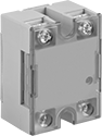 | 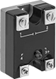 | 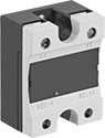 | 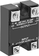 |
1-Circuit Relay with Covered Terminals and LED Indicator | 1-Circuit Relay with LED Indicator | 1-Circuit Relay with Covered Terminals | 1-Circuit Relay |
With no moving parts, these solid-state relays are fast switching and require less maintenance, last longer, and are quieter than mechanical switches.
Relays with High-Starting-Current Protection—Relays with high-starting-current protection are designed with integrated circuits that prevent damage from the large burst of electricity when a device, such as a motor or pump, turns on.
Switching Current @ Voltage | |||||||||||
|---|---|---|---|---|---|---|---|---|---|---|---|
No. of Terminals | Input Voltage | Without Heat Sink | With Heat Sink, amp | Max. Switching Voltage, V AC | Ht. | Wd. | Dp. | Each | |||
1 Circuit Controlled with 1 Off—SPST-NO | |||||||||||
Relays with High-Starting-Current Protection | |||||||||||
| 4 | 12V AC, 24V AC, 3V DC, 6V DC, 12V DC, 24V DC, 30V DC | 7.5 amp @ 300V AC | 25 | 300 | 2.3" | 1.8" | 1.1" | 7456K14 | 0000000 | ||
1 Circuit Controlled with 1 On—SPST-NC | |||||||||||
Relays with High-Starting-Current Protection | |||||||||||
| 4 | 12V AC, 24V AC, 3V DC, 6V DC, 12V DC, 24V DC, 30V DC | 7.5 amp @ 300V AC | 25 | 300 | 2.3" | 1.8" | 1.1" | 7456K16 | 000000 | ||
Hazardous Location Relays
 |  |
Screw Terminals | Spring-Clamp Terminals |
Sealed for safety, these relays are a good choice for hazardous locations where combustible or corrosive gases may be present.
Screw Terminals—Relays with screw terminals are considered interface relays, so they’re placed between your controller and components to isolate the input and output circuits. This means they protect your component from voltage spikes while amplifying the relay’s signal and reducing interference for reliable transmission. They are often used for switching applications, such as small motors and pilot lights. The included relay socket mounts on 35 mm DIN rail (also known as DIN 3 rail).
Spring-Clamp Terminals—Relays with spring-clamp terminals are considered interface relays, so they’re placed between your controller and components to isolate the input and output circuits. This means they protect your component from voltage spikes while amplifying the relay’s signal and reducing interference for reliable transmission. They are often used for switching applications, such as small motors and pilot lights. The included relay socket mounts on 35 mm DIN rail (also known as DIN 3 rail). Relays with spring-clamp terminals connect and disconnect to wires without needing to turn screws. With no screws to shake loose with vibration, the terminals hold tight over time.
No. of Terminals | Input Voltage | Control Current, mA | Switching Current @ Voltage | Max. Switching Voltage | Ht. | Wd. | Dp. | Enclosure Rating | Hazardous Location Rating | Each | |||
|---|---|---|---|---|---|---|---|---|---|---|---|---|---|
Screw Terminals | |||||||||||||
1 Circuit Controlled with 1 Off or 1 On—SPDT | |||||||||||||
| 5 | 12V AC, 12V DC | 15.5 | 6 amp @ 240V AC/30V DC | 400V AC/125V DC | 2.9" | 0.2" | 3.5" | IP20 | NEC Class I Division 2 Groups A, B, C, D | 4190N311 | 000000 | ||
| 5 | 12V AC, 12V DC | 29 | 12 amp @ 240V AC/24V DC | 400V AC/300V DC | 2.9" | 0.6" | 3.5" | IP20 | NEC Class I Division 2 Groups A, B, C, D | 4190N312 | 00000 | ||
Spring-Clamp Terminals | |||||||||||||
1 Circuit Controlled with 1 Off or 1 On—SPDT | |||||||||||||
| 5 | 12V AC, 12V DC | 15.5 | 6 amp @ 240V AC/30V DC | 400V AC/125V DC | 2.9" | 0.2" | 3.7" | IP20 | NEC Class I Division 2 Groups A, B, C, D | 8163N11 | 00000 | ||
| 5 | 12V AC, 12V DC | 29 | 12 amp @ 240V AC/24V DC | 400V AC/300V DC | 2.9" | 0.6" | 3.7" | IP20 | NEC Class I Division 2 Groups A, B, C, D | 8163N14 | 00000 | ||
Washdown Enclosed Relays
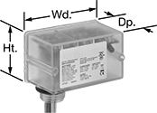 |
A NEMA 4X enclosure protects these relays from washdowns, dirt, and corrosion. It also keeps terminals from being bumped accidentally, so you can mount these relays near working areas. Hardwire to your equipment with the wire leads.
Wire Lead | Conduit Connection | |||||||||||||||
|---|---|---|---|---|---|---|---|---|---|---|---|---|---|---|---|---|
Input Voltage | Control Current, mA | Switching Current @ Voltage | Max. Switching Voltage, V AC | hp @ Switching Voltage | Ht. | Wd. | Dp. | Lg. | No. of | Gender | Trade Size | Thread Type | Each | |||
1 Circuit Controlled with 1 Off or 1 On—SPDT | ||||||||||||||||
| 12V AC, 24V AC, 120V AC, 12V DC, 24V DC, 30V DC | 28 | 10 amp @ 277V AC | 277 | 1/3 hp @ 240V AC | 1.7" | 2.8" | 1.5" | 16" | 6 | Male | 1/2 | NPT | 4766T11 | 000000 | ||
| 12V AC, 24V AC, 208V AC, 240V AC, 277V AC, 12V DC, 24V DC, 30V DC | 39 | 10 amp @ 277V AC | 277 | 1/3 hp @ 240V AC | 1.7" | 2.8" | 1.5" | 16" | 6 | Male | 1/2 | NPT | 4766T12 | 00000 | ||
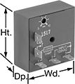
Smart DIN-Rail Mount Multifunction Timer Relays
 |
1 Circuit Controlled |
No. of Terminals | Input Voltage | Control Power, W | Timer Relay Function | Overall Timing Range | Switching Current @ Voltage | Max. Switching Voltage, V AC | Ht. | Wd. | Dp. | Operating System Compatibility | Features | Each | |||
|---|---|---|---|---|---|---|---|---|---|---|---|---|---|---|---|
1 Circuit Controlled with 1 Off or 1 On—SPDT | |||||||||||||||
| 8 | 12V AC, 24V AC, 48V AC, 120V AC, 240V AC, 12V DC, 24V DC, 48V DC, 60V DC, 120V DC, 240V DC | 0.15 | Manual Switch Control Fixed On/Off Switch on (Single Shot) Delayed Start (Delay on Make) Delayed Switch Off (Delay on Break) Delayed Switch-On with Delayed Switch-Off Interval Repeat Cycle Asymmetrical Repeat Cycle Switch-On Asymmetrical Repeat Cycle | 0.1 sec. to 999 day | 8 amp @ 240V AC | 250 | 4.1" | 0.7" | 2.5" | Android 5.0 or Later, iOS 14.4 or Later | LED Indicator | 8491N12 | 000000 | ||
Spade-Terminal Relays
Relay-Socket Mount
 |  |
8 Terminals | Sockets with Screw Terminals |
Relay-socket mount relays, also known as ice cube relays, offer three ways to connect. Plug them into a socket (sold separately), connect them with quick-disconnect terminals, or solder wires directly to the terminals.
Sockets with Screw Terminals—Relay sockets mount directly on 35 mm DIN rail (also known as DIN 3 rail) for fast installation. They can also mount to a flat surface.
Relays | Sockets with Screw Terminals | |||||||||||||
|---|---|---|---|---|---|---|---|---|---|---|---|---|---|---|
No. of Terminals | Input Voltage, V AC | Control Current, mA | Max. Switching Voltage, V AC | hp @ Switching Voltage | Ht. | Wd. | Dp. | Quick-Disconnect Tab Wd. | Each | Each | ||||
2 Circuits Controlled with 2 Off or 2 On—DPDT | ||||||||||||||
| 8 | 12 | 168 | 250 | 1/3 hp @ 120V AC 1/2 hp @ 240V AC | 1.4" | 1.5" | 1.9" | 0.187" | 7266K79 | 000000 | 7266K17 | 000000 | ||
Solid State Surface-Mount Timer Relays
 |
Attach these relays to a flat surface using the mounting hole. They have no moving parts, so compared to mechanical switches, they require less maintenance, last longer, and are quieter.
Delayed Start (Delay on Make)—Delayed start (delay on make) relays allow you to set how long it takes for the relay to turn on after input voltage is applied. For example, a drill starts pumping a lubricant immediately, but it does not start rotating until the set time has elapsed.
Potentiometer—Switches with a potentiometer (variable switch) allow you to adjust the delay within the range.
Timing Range | |||||||||||||
|---|---|---|---|---|---|---|---|---|---|---|---|---|---|
No. of Terminals | Input Voltage | Control Current, mA | No. of | Overall | Switching Current @ Voltage | Ht. | Wd. | Dp. | Features | Each | |||
Delayed Start (Delay on Make) | |||||||||||||
1 Circuit Controlled with 1 Off—SPST-NO | |||||||||||||
| 2 | 12V AC, 12V DC | 21 | 1 | 0.05 sec. to 1 sec. | 1 amp @ 120V AC | 2" | 2" | 0.89" | Potentiometer | 77055K731 | 0000000 | ||
| 2 | 12V AC, 12V DC | 21 | 1 | 0.25 sec. to 5 sec. | 1 amp @ 120V AC | 2" | 2" | 0.89" | Potentiometer | 77055K732 | 000000 | ||
| 2 | 12V AC, 12V DC | 21 | 1 | 0.5 sec. to 10 sec. | 1 amp @ 120V AC | 2" | 2" | 0.89" | Potentiometer | 77055K733 | 000000 | ||
| 2 | 12V AC, 12V DC | 21 | 1 | 3 sec. to 60 sec. | 1 amp @ 120V AC | 2" | 2" | 0.89" | Potentiometer | 77055K734 | 000000 | ||
| 2 | 12V AC, 12V DC | 21 | 1 | 15 sec. to 300 sec. | 1 amp @ 120V AC | 2" | 2" | 0.89" | Potentiometer | 77055K735 | 000000 | ||
| 2 | 12V AC, 12V DC | 21 | 1 | 30 sec. to 10 min. | 1 amp @ 120V AC | 2" | 2" | 0.89" | Potentiometer | 77055K736 | 000000 | ||
