


Filter by
Product Family
System of Measurement
Switch Designation
Number of Circuits Controlled
Switch Starting Position
Mounting Location
Horsepower @ Switching Voltage
Electrical Phase
Operation Type
Wire Connection
Electrical Connection
Switch Action
Relay Type

DFARS Specialty Metals
Export Control Classification Number (ECCN)
Mechanical Life Cycles
U.S.–Mexico–Canada Agreement (USMCA) Qualifying
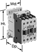
Screw Terminal Relays
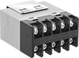 |  |
Use the screw terminals to hardwire these relays. The built-in enclosure protects contacts from dust and dirt. These relays accept voltage drops up to 50% of the rated voltage without switching. They’re often used with industrial automation systems, security and emergency lighting, and small motors. Also known as power relays.
No. of Terminals | Input Voltage | Control Current, mA | Switching Current @ Voltage | Max. Switching Voltage, V AC | hp @ Switching Voltage | Ht. | Wd. | Dp. | Each | |||
|---|---|---|---|---|---|---|---|---|---|---|---|---|
4 Circuits Controlled with 2 Off and 2 On—4PST-2NO/2NC | ||||||||||||
Surface Mount | ||||||||||||
| 10 | 120V AC | 22 | 25 amp @ 240V AC/24V DC (Off Circuit Position) 8 amp @ 240V AC/24V DC (On Circuit Position) | 250 | 1 1/2 hp @ 120V AC 3 hp @ 240V AC 3 hp @ 277V AC | 1.4" | 2" | 2.5" | 7105K15 | 000000 | ||
| 10 | 24V DC | 83 | 25 amp @ 240V AC/24V DC (Off Circuit Position) 8 amp @ 240V AC/24V DC (On Circuit Position) | 250 | 1 1/2 hp @ 120V AC 3 hp @ 240V AC 3 hp @ 277V AC | 1.4" | 2" | 2.5" | 7105K19 | 00000 | ||
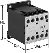
Machine-Guard Safety Relays
 |
Relay |
The interlocked opposing contacts won't close at the same time, so these relays are suitable for safety applications such as machine guarding. The screw terminals are recessed to prevent accidental contact with live connections. Mount them on 35 mm DIN rail (also known as DIN 3 rail) or flat surfaces. These relays are built to IEC dimensional standards.
No. of Terminals | Input Voltage, V AC | Control Current, mA | Switching Current @ Voltage | Max. Switching Voltage, V AC | Mechanical Life Cycles | Ht. | Wd. | Dp. | Features | Each | |||
|---|---|---|---|---|---|---|---|---|---|---|---|---|---|
4 Circuits Controlled with 2 Off and 2 On—4PST-2NO/2NC | |||||||||||||
| 10 | 24 | 125 | 10 amp @ 600V AC | 600 | 20,000,000 | 2.3" | 1.7" | 2.2" | Interlocked Opposing Contacts, Recessed Terminals | 7230K871 | 000000 | ||
| 10 | 120 | 25 | 10 amp @ 600V AC | 600 | 20,000,000 | 2.3" | 1.7" | 2.2" | Interlocked Opposing Contacts, Recessed Terminals | 7230K872 | 00000 | ||
| 10 | 240 | 12.5 | 10 amp @ 600V AC | 600 | 20,000,000 | 2.3" | 1.7" | 2.2" | Interlocked Opposing Contacts, Recessed Terminals | 7230K873 | 00000 | ||
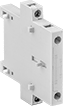
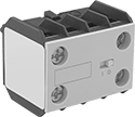 |
Auxiliary Contact |
No. of Circuits Controlled | Switch Starting Position | Switch Designation | Mounting Location | For Relay Wd. | Each | ||
|---|---|---|---|---|---|---|---|
| 2 | 1 Off and 1 On | DPST-1NO/1NC | Front | 1.7" | 70255K13 | 000000 |
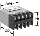
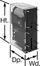
DIN-Rail Mount Touch-Safe Screw Terminal Relays
 |
Quickly and safely mount these relays on 35 mm DIN rail (also known as DIN 3). IP20 rated, they have recessed terminals that prevent fingers and other objects from touching live circuits.
4 Circuits Controlled—Relays that control 3 and 4 circuits are built to IEC dimensional standards and are often called IEC contactors.
No. of Terminals | Input Voltage, V DC | Control Current, mA | Switching Current @ Voltage (Load Type) | Max. Switching Voltage, V AC | Ht. | Wd. | Dp. | Each | |||
|---|---|---|---|---|---|---|---|---|---|---|---|
4 Circuits Controlled with 2 Off and 2 On—4PST-2NO/2NC | |||||||||||
| 10 | 24 | 133 | 10 amp @ 600V AC | 600 | 2.3" | 1.7" | 2.2" | 7230K93 | 0000000 | ||
 |  |
Front Mount | Side Mount |
No. of Circuits Controlled | For Relay Wd. | Switch Starting Position | Switch Designation | Mounting Location | Each | ||
|---|---|---|---|---|---|---|---|
| 2 | 1.7" | 1 Off and 1 On | DPST-1NO/1NC | Front | 70255K13 | 000000 |
Circuit Board Safety Relays
 |
10 Terminals |
Reduce connection errors on circuit boards that control machine guards and other safety devices. Also known as force-guided contact relays, they have contact pairs that won’t close at the same time, even if contacts stick or weld shut. These relays take up less space on a board than those with electrical wiring because their solder pin terminals mount directly through circuit board holes. Use them to control high-power components, such as fans and heaters, from a low-power circuit.
Surge Suppression Coverage—Relays with surge suppression coverage protect sensitive electronics from damage and malfunction by eliminating voltage spikes. Switching off a relay can generate surges of 300 to 500 volts, but a diode within these relays suppresses these surges. An LED indicator on these relays lights up when they’re on, so you know at a glance if they’re wired correctly.
No. of Terminals | Input Voltage, V DC | Control Current, mA | Switching Current @ Voltage | Max. Switching Voltage | Mechanical Life Cycles | Ht. | Wd. | Dp. | Pin Lg. | Features | Surge Suppression Coverage | Each | |||
|---|---|---|---|---|---|---|---|---|---|---|---|---|---|---|---|
4 Circuits Controlled with 2 Off and 2 On—4PST-2NO/2NC | |||||||||||||||
| 10 | 12 | 30 | 6 amp @ 240V AC/30V DC | 250V AC, 125V DC | 10,000,000 | 1.6" | 0.5" | 1" | 0.14" | Interlocked Opposing Contacts | — | 6253N15 | 000000 | ||
| 10 | 12 | 32 | 6 amp @ 240V AC/30V DC | 250V AC, 125V DC | 10,000,000 | 1.6" | 0.5" | 1" | 0.14" | Interlocked Opposing Contacts, LED Indicator | Full | 6253N25 | 00000 | ||
| 10 | 24 | 15 | 6 amp @ 240V AC/30V DC | 250V AC, 125V DC | 10,000,000 | 1.6" | 0.5" | 1" | 0.14" | Interlocked Opposing Contacts | — | 6253N14 | 00000 | ||
| 10 | 24 | 17 | 6 amp @ 240V AC/30V DC | 250V AC, 125V DC | 10,000,000 | 1.6" | 0.5" | 1" | 0.14" | Interlocked Opposing Contacts, LED Indicator | Full | 6253N26 | 00000 | ||
Safety Relays
SIL 2, PLd Max. System Safety Rating—DIN-Rail Mount
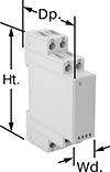 |
Relays that meet SIL 2 are tested for applications with a probability of failure of 0.1% to 1%. They’re often used for emergency shutdowns, and fire, gas, and overpressure detection.
No. of Terminals | Input Voltage | Control Current, mA | Switching Current @ Voltage | Max. Switching Voltage, V AC | Ht. | Wd. | Dp. | Features | Each | |||
|---|---|---|---|---|---|---|---|---|---|---|---|---|
Screw-Terminal Wire Connection | ||||||||||||
4 Circuits Controlled with 2 Off and 2 On—4PST-2NO/2NC | ||||||||||||
| 12 | 120V AC | 10 | 6 amp @ 240V AC | 250 | 3.4" | 0.9" | 3.9" | Interlocked Opposing Contacts, LED Indicator, Recessed Terminals | 6242N114 | 0000000 | ||
| 12 | 24V DC | 42 | 6 amp @ 240V AC | 250 | 3.4" | 0.9" | 3.9" | Interlocked Opposing Contacts, LED Indicator, Recessed Terminals | 6242N115 | 000000 | ||
