


Filter by
Switching Current
Socket Connection
Mounting Location
Electrical Connection


Horsepower @ Switching Voltage
Switch Action
Electrical Phase
Switch Starting Position
Wire Connection


Operation Type
Control Current
Certification
U.S.–Mexico–Canada Agreement (USMCA) Qualifying
DFARS Specialty Metals
Export Control Classification Number (ECCN)
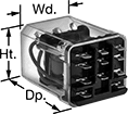
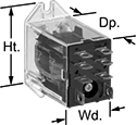
Compact Spade-Terminal Relays
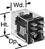 |  |  |
8-Terminal Relay (1 Circuit Controlled) | 11-Terminal Relay | 14-Terminal Relay |
 |  |  |
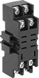
11-Terminal Relay Socket | 14-Terminal Relay Socket | 8-Terminal Relay Socket |
Fit these relays where standard spade-terminal relays are too big. You can connect them three ways. Plug them into a socket (sold separately), connect them with quick-disconnect terminals, or solder wires directly to the terminals. An LED indicator shows you the status of the relay, so you know it’s connected and wired correctly.
2 Circuits Controlled, 3 Circuits Controlled, and 4 Circuits Controlled—Relays that control 2 or more circuits have a lockable test button, so you can test their function. When you press the button, the relay switches contacts. Use this button when checking a relay for proper function before installing it, or when investigating issues with wired relays.
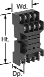
Sockets with Screw Terminals—Relay sockets mount directly on 35 mm DIN rail (also known as DIN 3 rail) for fast installation. You can also mount them to a flat surface using screws.
Relays | Sockets with Screw Terminals | |||||||||||||||
|---|---|---|---|---|---|---|---|---|---|---|---|---|---|---|---|---|
No. of Terminals | Input Voltage | Control Current, mA | Switching Current @ Voltage | Max. Switching Voltage, V AC | hp @ Switching Voltage | Ht. | Wd. | Dp. | Quick-Disconnect Tab Wd. | Features | Each | Each | ||||
1 Circuit Controlled with 1 Off or 1 On—SPDT | ||||||||||||||||
Relay-Socket Mount | ||||||||||||||||
| 8 | 24V AC | 46 | 15 amp @ 120V AC/24V DC | 250 | — | 1.1" | 0.9" | 1.6" | 0.197" | LED Indicator | 69585K11 | 000000 | 69585K5 | 000000 | ||
| 8 | 120V AC | 9 | 15 amp @ 120V AC/24V DC | 250 | — | 1.1" | 0.9" | 1.6" | 0.197" | LED Indicator | 69585K12 | 00000 | 69585K5 | 00000 | ||
| 8 | 24V DC | 37 | 15 amp @ 120V AC/24V DC | 250 | — | 1.1" | 0.9" | 1.6" | 0.197" | LED Indicator | 69585K25 | 00000 | 69585K5 | 00000 | ||
2 Circuits Controlled with 2 Off or 2 On—DPDT | ||||||||||||||||
Relay-Socket Mount | ||||||||||||||||
| 8 | 24V AC | 50 | 15 amp @ 120V AC 12 amp @ 24V DC | 300 | 1/2 hp @ 120V AC 1 hp @ 277V AC | 1.1" | 0.9" | 1.6" | 0.187" | LED Indicator, Lockable Test Button, Mechanical Flag Indicator | 69585K57 | 00000 | 69585K1 | 0000 | ||
| 8 | 120V AC | 10 | 15 amp @ 120V AC 12 amp @ 24V DC | 300 | 1/2 hp @ 120V AC 1 hp @ 277V AC | 1.1" | 0.9" | 1.6" | 0.187" | LED Indicator, Lockable Test Button, Mechanical Flag Indicator | 69585K58 | 00000 | 69585K1 | 0000 | ||
| 8 | 240V AC | 5 | 15 amp @ 120V AC 12 amp @ 24V DC | 300 | 1/2 hp @ 120V AC 1 hp @ 277V AC | 1.1" | 0.9" | 1.6" | 0.187" | LED Indicator, Lockable Test Button, Mechanical Flag Indicator | 69585K59 | 00000 | 69585K1 | 0000 | ||
| 8 | 12V DC | 75 | 15 amp @ 120V AC 12 amp @ 24V DC | 300 | 1/2 hp @ 120V AC 1 hp @ 277V AC | 1.1" | 0.9" | 1.6" | 0.187" | LED Indicator, Lockable Test Button, Mechanical Flag Indicator | 69585K66 | 00000 | 69585K1 | 0000 | ||
| 8 | 24V DC | 38 | 15 amp @ 120V AC 12 amp @ 24V DC | 300 | 1/2 hp @ 120V AC 1 hp @ 277V AC | 1.1" | 0.9" | 1.6" | 0.187" | LED Indicator, Lockable Test Button, Mechanical Flag Indicator | 69585K67 | 00000 | 69585K1 | 0000 | ||
3 Circuits Controlled with 3 Off or 3 On—3PDT | ||||||||||||||||
Relay-Socket Mount | ||||||||||||||||
| 11 | 24V AC | 63 | 15 amp @ 120V AC 12 amp @ 24V DC | 300 | 1/2 hp @ 120V AC 1 hp @ 277V AC | 1.1" | 1.2" | 1.6" | 0.187" | LED Indicator, Lockable Test Button, Mechanical Flag Indicator | 69585K68 | 00000 | 69585K2 | 00000 | ||
| 11 | 120V AC | 13 | 15 amp @ 120V AC 12 amp @ 24V DC | 300 | 1/2 hp @ 120V AC 1 hp @ 277V AC | 1.1" | 1.2" | 1.6" | 0.187" | LED Indicator, Lockable Test Button, Mechanical Flag Indicator | 69585K69 | 00000 | 69585K2 | 00000 | ||
| 11 | 240V AC | 6 | 15 amp @ 120V AC 12 amp @ 24V DC | 300 | 1/2 hp @ 120V AC 1 hp @ 277V AC | 1.1" | 1.2" | 1.6" | 0.187" | LED Indicator, Lockable Test Button, Mechanical Flag Indicator | 69585K71 | 00000 | 69585K2 | 00000 | ||
| 11 | 12V DC | 117 | 15 amp @ 120V AC 12 amp @ 24V DC | 300 | 1/2 hp @ 120V AC 1 hp @ 277V AC | 1.1" | 1.2" | 1.6" | 0.187" | LED Indicator, Lockable Test Button, Mechanical Flag Indicator | 69585K72 | 00000 | 69585K2 | 00000 | ||
| 11 | 24V DC | 58 | 15 amp @ 120V AC 12 amp @ 24V DC | 300 | 1/2 hp @ 120V AC 1 hp @ 277V AC | 1.1" | 1.2" | 1.6" | 0.187" | LED Indicator, Lockable Test Button, Mechanical Flag Indicator | 69585K73 | 00000 | 69585K2 | 00000 | ||
4 Circuits Controlled with 4 Off or 4 On—4PDT | ||||||||||||||||
Relay-Socket Mount | ||||||||||||||||
| 14 | 24V AC | 63 | 15 amp @ 120V AC 12 amp @ 24V DC | 300 | 1/2 hp @ 120V AC 1 hp @ 277V AC | 1.1" | 1.6" | 1.6" | 0.187" | LED Indicator, Lockable Test Button, Mechanical Flag Indicator | 69585K74 | 00000 | 69585K3 | 00000 | ||
| 14 | 120V AC | 13 | 15 amp @ 120V AC 12 amp @ 24V DC | 300 | 1/2 hp @ 120V AC 1 hp @ 277V AC | 1.1" | 1.6" | 1.6" | 0.187" | LED Indicator, Lockable Test Button, Mechanical Flag Indicator | 69585K79 | 00000 | 69585K3 | 00000 | ||
| 14 | 12V DC | 125 | 15 amp @ 120V AC 12 amp @ 24V DC | 300 | 1/2 hp @ 120V AC 1 hp @ 277V AC | 1.1" | 1.6" | 1.6" | 0.187" | LED Indicator, Lockable Test Button, Mechanical Flag Indicator | 69585K55 | 00000 | 69585K3 | 00000 | ||
| 14 | 24V DC | 6 | 15 amp @ 120V AC 12 amp @ 24V DC | 300 | 1/2 hp @ 120V AC 1 hp @ 277V AC | 1.1" | 1.6" | 1.6" | 0.187" | LED Indicator, Lockable Test Button, Mechanical Flag Indicator | 69585K96 | 00000 | 69585K3 | 00000 | ||
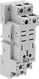
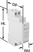
Relay Sockets
 |  |
Style E | Style J |
Style | No. of Terminals | For Quick-Disconnect Tab Wd. | For Switching Current @ Voltage | For Max. Switching Voltage, V AC | Ht. | Wd. | Dp. | Features | Each | |||
|---|---|---|---|---|---|---|---|---|---|---|---|---|
Quick-Disconnect-Terminal Relay Connection | ||||||||||||
Screw-Terminal Wire Connection | ||||||||||||
| E | 8 | 0.197" | 15 amp @ 120V AC | 250 | 3.1" | 1.2" | 1.3" | Recessed Terminals | 69585K5 | 000000 | ||
| J | 8 | 0.187" | 15 amp @ 120V AC | 300 | 3.1" | 1.2" | 1.3" | Recessed Terminals | 69585K1 | 0000 | ||
| J | 11 | 0.187" | 15 amp @ 120V AC | 300 | 3.1" | 1.6" | 1.2" | Recessed Terminals | 69585K2 | 00000 | ||
| J | 14 | 0.187" | 15 amp @ 120V AC | 300 | 3.1" | 2" | 1.2" | Recessed Terminals | 69585K3 | 00000 | ||
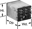
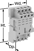
Spade-Terminal Relays
Relay-Socket Mount
 |  |
11 Terminals | Sockets with Screw Terminals |
Relay-socket mount relays, also known as ice cube relays, offer three ways to connect. Plug them into a socket (sold separately), connect them with quick-disconnect terminals, or solder wires directly to the terminals.
Sockets with Screw Terminals—Relay sockets mount directly on 35 mm DIN rail (also known as DIN 3 rail) for fast installation. They can also mount to a flat surface.
Relays | Sockets with Screw Terminals | |||||||||||||
|---|---|---|---|---|---|---|---|---|---|---|---|---|---|---|
No. of Terminals | Input Voltage | Control Current, mA | Max. Switching Voltage, V AC | hp @ Switching Voltage | Ht. | Wd. | Dp. | Quick-Disconnect Tab Wd. | Each | Each | ||||
3 Circuits Controlled with 3 Off or 3 On—3PDT | ||||||||||||||
| 11 | 120V AC | 24 | 250 | 1/2 hp @ 120V AC 1/2 hp @ 240V AC | 1.4" | 1.5" | 1.9" | 0.187" | 7266K55 | 000000 | 7266K17 | 000000 | ||
| 11 | 12V DC | 100 | 250 | 1/2 hp @ 120V AC 1/2 hp @ 240V AC | 1.4" | 1.5" | 1.9" | 0.187" | 7266K45 | 00000 | 7266K17 | 00000 | ||
| 11 | 24V DC | 51 | 250 | 1/2 hp @ 120V AC 1/2 hp @ 240V AC | 1.4" | 1.5" | 1.9" | 0.187" | 7266K53 | 00000 | 7266K17 | 00000 | ||
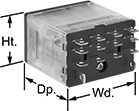
Relay-Socket Mount/Surface Mount
 |  |
8 Terminals (1 Circuit Controlled) | Sockets with Screw Terminals |
Relay-socket/surface mount relays can plug into a socket or mount to a flat surface.
Relay-socket mount relays, also known as ice cube relays, offer three ways to connect. Plug them into a socket (sold separately), connect them with quick-disconnect terminals, or solder wires directly to the terminals.
Surface mount relays, also known as power relays, have a slot on the flange for mounting them to flat surfaces.
Sockets with Screw Terminals—Relay sockets mount directly on 35 mm DIN rail (also known as DIN 3 rail) for fast installation. They can also mount to a flat surface.
Relays | Sockets with Screw Terminals | |||||||||||||
|---|---|---|---|---|---|---|---|---|---|---|---|---|---|---|
No. of Terminals | Input Voltage | Control Current, mA | Max. Switching Voltage, V AC | hp @ Switching Voltage | Ht. | Wd. | Dp. | Quick-Disconnect Tab Wd. | Each | Each | ||||
1 Circuit Controlled with 1 Off or 1 On—SPDT | ||||||||||||||
| 8 | 24V AC | 46 | 250 | 1/2 hp @ 120V AC | 1.8" | 0.9" | 1.4" | 0.2" | 70315K11 | 000000 | 7122K22 | 000000 | ||
| 8 | 120V AC | 9 | 250 | 1/2 hp @ 120V AC | 1.8" | 0.9" | 1.4" | 0.2" | 70315K12 | 00000 | 7122K22 | 00000 | ||
| 8 | 24V DC | 37 | 250 | 1/2 hp @ 120V AC | 1.8" | 0.9" | 1.4" | 0.2" | 70315K41 | 00000 | 7122K22 | 00000 | ||
DIN-Rail Mount Solid State Relays
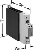 | 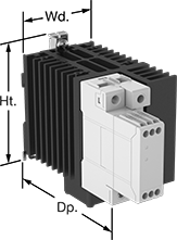 |  |
Relay with Integrated Heat Sink | Relay with Integrated Heat Sink and Fan | Relay |
No. of Terminals | Input Voltage | Control Current, mA | Switching Current @ Voltage (Load Type) | Max. Switching Voltage, V DC | Ht. | Wd. | Dp. | Features | Each | |||
|---|---|---|---|---|---|---|---|---|---|---|---|---|
1 Circuit Controlled with 1 Off—SPST-NO | ||||||||||||
Single Phase | ||||||||||||
| 4 | 24V DC | 18 | 15 amp @ 24V DC (Resistive) | 32 | 3.496" | 0.689" | 2.394" | LED Indicator | 4286N15 | 000000 | ||
Air-Actuated Relays
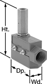 |
Also known as an air-to-electric switch, this relay converts an air signal to an electric signal. Use it to actuate solenoid valves and other electric components from your pneumatic control system.
Air Connection | Conduit Connection | |||||||||||||||
|---|---|---|---|---|---|---|---|---|---|---|---|---|---|---|---|---|
No. of Terminals | Switching Current @ Voltage | Max. Switching Voltage, V AC | Air Pressure, psi | Pipe Size | Thread Type | Gender | Ht. | Wd. | Dp. | Trade Size | Thread Type | Gender | Each | |||
1 Circuit Controlled with 1 Off or 1 On—SPDT | ||||||||||||||||
| 3 | 15 amp @ 240V AC | 250 | 8 to 100 | 1/8 | NPT | Female | 3.6" | 1" | 3.1" | 1/2 | NPSM | Female | 49145K51 | 0000000 | ||
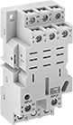
Infrequent-Cycle Relays
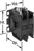 |  |
2 Circuits | 3 Circuits |
For use with equipment that cycles on and off, these relays meet UL 508 for air conditioning and heating. Connections are accessible from the front, so you can mount relays side-by-side. Also known as definite-purpose contactors.
Auxiliary contacts for 3.8"-7.2" Ht. relays are also available. They allow you to add a signaling device or control another relay. Please select 6564K99, then select the McMaster-Carr part number of your relay and whether you want to switch one circuit on or off.
Switching Current @ 600V AC, amp | hp @ Switching Voltage | |||||||||||||
|---|---|---|---|---|---|---|---|---|---|---|---|---|---|---|
No. of Terminals | Input Voltage | Control Power | Full Load | Resistive Load | Single Phase | Three Phase | Ht. | Wd. | Dp. | Quick-Disconnect Tab Wd. | Each | |||
2 Circuits Controlled with 2 Off—DPST-NO | ||||||||||||||
Quick-Disconnect × Screw Terminal | ||||||||||||||
| 4 | 24V AC | 7 VA | 15 | 20 | 3/4 hp @ 115V AC 2 hp @ 230V AC | 3 hp @ 230V AC 5 hp @ 460V AC 5 hp @ 575V AC | 3.8" | 2.4" | 3.4" | 0.25" | 6564K911 | 000000 | ||
| 4 | 120V AC | 7 VA | 15 | 20 | 3/4 hp @ 115V AC 2 hp @ 230V AC | 3 hp @ 230V AC 5 hp @ 460V AC 5 hp @ 575V AC | 3.8" | 2.4" | 3.4" | 0.25" | 6564K912 | 00000 | ||
| 4 | 208V AC, 240V AC | 7 VA | 15 | 20 | 3/4 hp @ 115V AC 2 hp @ 230V AC | 3 hp @ 230V AC 5 hp @ 460V AC 5 hp @ 575V AC | 3.8" | 2.4" | 3.4" | 0.25" | 6564K913 | 00000 | ||
| 4 | 24V DC | 3.1 W | 15 | 20 | 3/4 hp @ 115V AC 2 hp @ 230V AC | 3 hp @ 230V AC 5 hp @ 460V AC 5 hp @ 575V AC | 3.8" | 2.4" | 3.4" | 0.25" | 6564K511 | 000000 | ||
3 Circuits Controlled with 3 Off—3PST-NO | ||||||||||||||
Quick-Disconnect × Screw Terminal | ||||||||||||||
| 6 | 24V AC | 7 VA | 15 | 20 | 3/4 hp @ 115V AC 2 hp @ 230V AC | 3 hp @ 230V AC 5 hp @ 460V AC 5 hp @ 575V AC | 3.8" | 2.4" | 3.4" | 0.25" | 6564K921 | 000000 | ||
| 6 | 120V AC | 7 VA | 15 | 20 | 3/4 hp @ 115V AC 2 hp @ 230V AC | 3 hp @ 230V AC 5 hp @ 460V AC 5 hp @ 575V AC | 3.8" | 2.4" | 3.4" | 0.25" | 6564K922 | 000000 | ||
| 6 | 208V AC, 240V AC | 7 VA | 15 | 20 | 3/4 hp @ 115V AC 2 hp @ 230V AC | 3 hp @ 230V AC 5 hp @ 460V AC 5 hp @ 575V AC | 3.8" | 2.4" | 3.4" | 0.25" | 6564K923 | 000000 | ||
| 6 | 24V DC | 3.1 W | 15 | 20 | 3/4 hp @ 115V AC 2 hp @ 230V AC | 3 hp @ 230V AC 5 hp @ 460V AC 5 hp @ 575V AC | 3.8" | 2.4" | 3.4" | 0.25" | 6564K512 | 000000 | ||
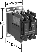
Manual Transfer Switches
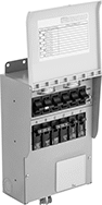 | 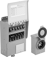 | 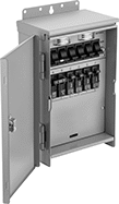 |
NEMA 1 | NEMA 1 with NEMA 3R Power Inlet Box | NEMA 3R |
If there’s a power outage, flip the toggle for each circuit on these switches to backup power. Each circuit can also be turned off completely. To prevent injury and damage to your generators, they are open transition, meaning the contacts disconnect from one power source before connecting to another. This is also known as break-before-make switching.
Use them with a portable generator.
NEMA 1—NEMA 1 switches should be used indoors.
NEMA 1 with NEMA 3R Power Inlet Box—NEMA 1 switches with a power inlet box create a connection point between the switch and a portable generator. These switches should be used indoors. But their inlet box is rated NEMA 3R, so it can be mounted on the outside of an exterior wall.
NEMA 3R—NEMA 3R switches can be used outdoors since they seal out rain, snow, and sleet.
Key Lock—Switches with a key lock prevent unauthorized changes to the switch.
Housing | Mounting | |||||||||||||||||||
|---|---|---|---|---|---|---|---|---|---|---|---|---|---|---|---|---|---|---|---|---|
Max. Power, W | Switching Current (No. of Switches) | Circuit Breaker Breakthrough Current, amp | Electrical Phase | Housing Material | Ht. | Wd. | Dp. | Generator Connection NEMA Type | Generator Connection California Std. Style | Power Cord Lg., ft. | Fasteners Included | No. of Holes | Hole Dia. | Features | Certification | Specs. Met | Each | |||
NEMA 1 | ||||||||||||||||||||
10 Circuits Controlled | ||||||||||||||||||||
| 7,500 | 30 amp @ 240V AC (1 DPDT) 20 amp @ 240V AC (1 DPDT) 15 amp @ 120V AC (6 SPDT) | 10,000 | Single | Powder-Coated Steel | 11 1/4" | 11 3/4" | 4 3/4" | L14-30 | — | — | Yes | 5 | 1/4" | — | UL Listed | UL 1008, NEC Article 702 | 4272N18 | 0000000 | ||
NEMA 1 with NEMA 3R Power Inlet Box | ||||||||||||||||||||
6 Circuits Controlled | ||||||||||||||||||||
| 7,500 | 20 amp @ 240V AC (1 DPDT) 15 amp @ 120V AC (4 SPDT) | 10,000 | Single | Powder-Coated Steel | 12" | 8 3/4" | 6" | L14-30 | — | 10 | Yes | 5 | 1/4" | — | UL Listed | UL 1008, NEC Article 702 | 4272N11 | 000000 | ||
10 Circuits Controlled | ||||||||||||||||||||
| 7,500 | 20 amp @ 240V AC (1 DPDT) 20 amp @ 120V AC (2 SPDT) 15 amp @ 120V AC (6 SPDT) | 10,000 | Single | Powder-Coated Steel | 11 1/4" | 11 3/4" | 4 3/4" | L14-30 | — | 10 | Yes | 5 | 1/4" | — | UL Listed | UL 1008, NEC Article 702 | 4272N12 | 000000 | ||
NEMA 3R | ||||||||||||||||||||
10 Circuits Controlled | ||||||||||||||||||||
| 7,500 | 20 amp @ 240V AC (1 DPDT) 20 amp @ 120V AC (2 SPDT) 15 amp @ 120V AC (6 SPDT) | 10,000 | Single | Powder-Coated Steel | 12 3/4" | 12" | 5" | L14-30 | — | — | Yes | 5 | 1/4" | Key Lock | UL Listed | UL 1008, NEC Article 702 | 4272N14 | 000000 | ||
| 12,500 | 20 amp @ 240V AC (1 DPDT) 20 amp @ 120V AC (2 SPDT) 15 amp @ 120V AC (6 SPDT) | 10,000 | Single | Powder-Coated Steel | 12 3/4" | 12" | 5" | — | CS6375 | — | Yes | 5 | 1/4" | Key Lock | UL Listed | UL 1008, NEC Article 702 | 4272N16 | 000000 | ||
