


Filter by
Switching Voltage
Switching Current
Wire Connection


Switch Starting Position
Operation Type
Electrical Connection

Horsepower @ Switching Voltage
Relay Type

Switch Action
U.S.–Mexico–Canada Agreement (USMCA) Qualifying
Export Control Classification Number (ECCN)
RoHS
REACH
DFARS Specialty Metals
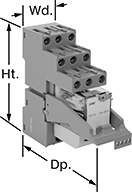
DIN-Rail Mount Interface Relays
4 Circuits Controlled with 4 Off or 4 On—4PDT
 | 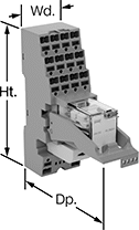 |
With Screw Terminals | With Spring-Clamp Terminals |
Interface Relays | Replacement Relays | ||||||||||||||
|---|---|---|---|---|---|---|---|---|---|---|---|---|---|---|---|
No. of Terminals | Input Voltage | Control Current, mA | Switching Current @ Voltage | Max. Switching Voltage, V AC | hp @ Switching Voltage | Ht. | Wd. | Dp. | Features | Each | Each | ||||
With Screw Terminals | |||||||||||||||
| 14 | 24V AC | 53 | 7 amp @ 240V AC | 250 | 1/8 hp @ 120V AC | 3.1" | 1.1" | 3.3" | LED Indicator, PLC Output Protection | 4144N109 | 000000 | 4144N124 | 000000 | ||
| 14 | 120V AC | 12 | 7 amp @ 240V AC | 250 | 1/8 hp @ 120V AC | 3.1" | 1.1" | 3.3" | LED Indicator, PLC Output Protection | 4144N111 | 00000 | 4144N125 | 00000 | ||
| 14 | 12V DC | 86 | 7 amp @ 240V AC | 250 | 1/8 hp @ 120V AC | 3.1" | 1.1" | 3.3" | LED Indicator, PLC Output Protection | 4144N113 | 00000 | 4144N127 | 00000 | ||
| 14 | 24V DC | 40 | 7 amp @ 240V AC | 250 | 1/8 hp @ 120V AC | 3.1" | 1.1" | 3.3" | LED Indicator, PLC Output Protection | 4144N112 | 00000 | 4144N126 | 00000 | ||
With Spring-Clamp Terminals | |||||||||||||||
| 14 | 24V AC | 53 | 7 amp @ 240V AC | 250 | 1/8 hp @ 120V AC | 3.9" | 1.2" | 3.3" | LED Indicator, PLC Output Protection | 4144N118 | 00000 | 4144N124 | 00000 | ||
| 14 | 12V DC | 86 | 7 amp @ 240V AC | 250 | 1/8 hp @ 120V AC | 3.9" | 1.2" | 3.3" | LED Indicator, PLC Output Protection | 4144N121 | 00000 | 4144N127 | 00000 | ||
| 14 | 24V DC | 40 | 7 amp @ 240V AC | 250 | 1/8 hp @ 120V AC | 3.9" | 1.2" | 3.3" | LED Indicator, PLC Output Protection | 4144N119 | 00000 | 4144N126 | 00000 | ||
Solid State Screw Terminal Relays
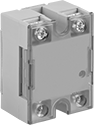 | 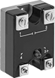 | 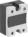 |
1-Circuit Relay with Covered Terminals and LED Indicator | 1-Circuit Relay with LED Indicator | 1-Circuit Relay with Covered Terminals |
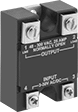 | 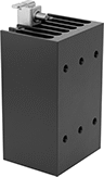 | |
1-Circuit Relay | Heat Sinks |
With no moving parts, these solid-state relays are fast switching and require less maintenance, last longer, and are quieter than mechanical switches.
Relays with High-Starting-Current Protection—Relays with high-starting-current protection are designed with integrated circuits that prevent damage from the large burst of electricity when a device, such as a motor or pump, turns on.
LED Indicator—Relays with LED indicator let you quickly spot whether a relay is on or off.
Heat Sinks—Heat sinks disperse heat to increase the relay’s current rating. Mount them to 35 mm DIN rail (also known as DIN 3 rail) for fast installation. They also mount to flat surfaces. Before mounting one-circuit relays, silicone compound or a thermal pad should be placed between the heat sink and relay. Silicone compound is sold separately for heat sinks that do not include it but require it. Two-circuit relays don’t require silicone for mounting.
Relays | Heat Sinks | Silicone Compounds | |||||||||||||
|---|---|---|---|---|---|---|---|---|---|---|---|---|---|---|---|
Switching Current @ Voltage | |||||||||||||||
No. of Terminals | Input Voltage | Without Heat Sink | With Heat Sink, amp | Max. Switching Voltage, V AC | Ht. | Wd. | Dp. | Each | Each | Each | |||||
1 Circuit Controlled with 1 Off—SPST-NO | |||||||||||||||
Relays with High-Starting-Current Protection | |||||||||||||||
| 4 | 85V AC, 120V AC, 240V AC, 280V AC | 7 amp @ 120V AC | 25 | 140 | 2.3" | 1.8" | 1" | 7456K17 | 000000 | 7456K222 | 000000 | 10405K79 | 000000 | ||
| 4 | 85V AC, 120V AC, 240V AC, 280V AC | 7 amp @ 240V AC | 25 | 280 | 2.3" | 1.8" | 1" | 7456K23 | 00000 | 7456K222 | 00000 | 10405K79 | 00000 | ||
| 4 | 3V DC, 6V DC, 12V DC, 24V DC, 30V DC | 7 amp @ 120V AC | 25 | 140 | 2.3" | 1.8" | 1" | 7456K21 | 00000 | 7456K222 | 00000 | 10405K79 | 00000 | ||
| 4 | 3V DC, 6V DC, 12V DC, 24V DC, 30V DC | 7 amp @ 240V AC | 25 | 280 | 2.3" | 1.8" | 1" | 7456K25 | 00000 | 7456K222 | 00000 | 10405K79 | 00000 | ||
| 4 | 3V DC, 6V DC, 12V DC, 24V DC, 30V DC | 7 amp @ 380V AC | 25 | 420 | 2.3" | 1.8" | 1" | 7456K132 | 00000 | 7456K222 | 00000 | 10405K79 | 00000 | ||
Relays with High-Starting-Current Protection and Covered Terminals and LED Indicator | |||||||||||||||
| 4 | 120V AC, 240V AC | 7 amp @ 240V AC | 75 | 240 | 2.3" | 1.8" | 1.1" | 7456K66 | 000000 | 7456K69 | 000000 | 10405K79 | 00000 | ||
| 4 | 120V AC, 240V AC | 7 amp @ 240V AC | 90 | 240 | 2.3" | 1.8" | 1.1" | 7456K67 | 000000 | 7456K69 | 000000 | 10405K79 | 00000 | ||
Relays with High-Starting-Current Protection and LED Indicator | |||||||||||||||
| 4 | 3V DC, 6V DC, 12V DC, 24V DC, 30V DC | 7 amp @ 240V AC | 25 | 280 | 2.3" | 1.8" | 1" | 7456K27 | 00000 | 7456K222 | 00000 | 10405K79 | 00000 | ||
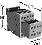
Safety Relays
SIL 3, PLe, Cat. 4 Max. System Safety Rating—DIN-Rail Mount, Surface Mount
 |
Relays that meet SIL 3 are tested for applications with a probability of failure of 0.01% to 0.1% and are used for preventing fires, explosions, or toxic releases.
Relays that meet Cat. 4 withstand circuit surges in electrical applications up to 600V.
Mirror Auxiliary Contacts—Relays with mirror auxiliary contacts have contacts that are normally closed and cannot be open at the same time as a normally open main contact.
Nondetachable Auxiliary Contacts—Relays with nondetachable contacts have auxiliary contacts that won’t separate from the relay if there is shock or vibration.
Self-Monitoring Circuitry—When a failure is detected, relays with self-monitoring circuitry signal the controller to remove power and prevent restarting until the issue is resolved.
hp @ Switching Voltage | |||||||||||||||
|---|---|---|---|---|---|---|---|---|---|---|---|---|---|---|---|
No. of Terminals | Input Voltage | Control Current, mA | Switching Current @ Voltage | Max. Switching Voltage, V AC | Single Phase | Three Phase | Aux. Contact Switch Starting Position | Ht. | Wd. | Dp. | Features | Each | |||
Screw-Terminal Wire Connection | |||||||||||||||
3 Circuits Controlled with 3 Off—3PST-NO | |||||||||||||||
| 18 | 120V AC | 2 | 7 amp @ 400V AC | 600 | 1/4 hp @ 120V AC 1 hp @ 240V AC | 2 hp @ 240V AC 3 hp @ 480V AC 5 hp @ 600V AC | 2 Off and 3 On | 2.7" | 1.8" | 4.6" | Inspection Window, Interlocked Opposing Contacts, Mirror Auxiliary Contacts, Nondetachable Auxiliary Contacts, Recessed Terminals, Self-Monitoring Circuitry | 6242N11 | 0000000 | ||
| 18 | 24V DC | 12 | 7 amp @ 400V AC | 600 | 1/4 hp @ 120V AC 1 hp @ 240V AC | 2 hp @ 240V AC 3 hp @ 480V AC 5 hp @ 600V AC | 2 Off and 3 On | 2.7" | 1.8" | 4.6" | Inspection Window, Interlocked Opposing Contacts, Mirror Auxiliary Contacts, Nondetachable Auxiliary Contacts, Recessed Terminals, Self-Monitoring Circuitry | 6242N15 | 000000 | ||
