



























Filter by
Input Voltage

Switch Designation
Switching Voltage
Mounting Location
Switching Current
Timer Function
Electrical Phase
Operation Type
Switch Starting Position
Wire Connection


Socket Connection


Overall Timing
Timing Adjustment Style


Certification
Control Current
DFARS Specialty Metals
Export Control Classification Number (ECCN)
DIN-Rail Mount Interface Relays
2 Circuits Controlled with 2 Off or 2 On—DPDT
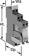 |
With Screw Terminals |
PLC Output Protection—Relays with PLC output protection prevent voltage spikes created by the relay from damaging the output channel on your programmable logic controller (PLC).
Interface Relays | Replacement Relays | ||||||||||||||
|---|---|---|---|---|---|---|---|---|---|---|---|---|---|---|---|
No. of Terminals | Input Voltage | Control Current, mA | Switching Current @ Voltage | Max. Switching Voltage, V AC | hp @ Switching Voltage | Ht. | Wd. | Dp. | Features | Each | Each | ||||
With Screw Terminals | |||||||||||||||
| 8 | 24V AC | 45 | 8 amp @ 240V AC | 250 | 1/4 hp @ 120V AC | 3.3" | 0.6" | 2.7" | LED Indicator, PLC Output Protection | 7098K44 | 000000 | 7098K64 | 000000 | ||
| 8 | 120V AC | 8 | 8 amp @ 240V AC | 250 | 1/4 hp @ 120V AC | 3.3" | 0.6" | 2.7" | LED Indicator, PLC Output Protection | 7098K45 | 00000 | 7098K65 | 00000 | ||
| 8 | 120V AC, 120V DC | 4.5 | 8 amp @ 240V AC | 250 | 1/2 hp @ 120V AC | 3.5" | 0.6" | 3" | LED Indicator | 4144N13 | 00000 | 4026N13 | 0000 | ||
| 8 | 240V AC, 240V DC | 5 | 8 amp @ 240V AC | 250 | 1/2 hp @ 120V AC | 3.5" | 0.6" | 3" | LED Indicator | 4144N14 | 00000 | 4026N13 | 0000 | ||
| 8 | 24V DC | 20 | 8 amp @ 240V AC | 250 | 1/4 hp @ 120V AC | 3.3" | 0.6" | 2.7" | LED Indicator, PLC Output Protection | 7098K46 | 00000 | 7098K66 | 0000 | ||
Compact Spade-Terminal Relays
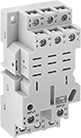 |  | 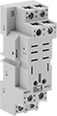 |
11-Terminal Relay Socket | 14-Terminal Relay Socket | 8-Terminal Relay Socket |
Fit these relays where standard spade-terminal relays are too big. You can connect them three ways. Plug them into a socket (sold separately), connect them with quick-disconnect terminals, or solder wires directly to the terminals. An LED indicator shows you the status of the relay, so you know it’s connected and wired correctly.
4 Circuits Controlled—Relays that control 2 or more circuits have a lockable test button, so you can test their function. When you press the button, the relay switches contacts. Use this button when checking a relay for proper function before installing it, or when investigating issues with wired relays.
Sockets with Screw Terminals—Relay sockets mount directly on 35 mm DIN rail (also known as DIN 3 rail) for fast installation. You can also mount them to a flat surface using screws.
Relays | Sockets with Screw Terminals | |||||||||||||||
|---|---|---|---|---|---|---|---|---|---|---|---|---|---|---|---|---|
No. of Terminals | Input Voltage | Control Current, mA | Switching Current @ Voltage | Max. Switching Voltage, V AC | hp @ Switching Voltage | Ht. | Wd. | Dp. | Quick-Disconnect Tab Wd. | Features | Each | Each | ||||
4 Circuits Controlled with 4 Off or 4 On—4PDT | ||||||||||||||||
Relay-Socket Mount | ||||||||||||||||
| 14 | 24V AC | 50 | 8 amp @ 120V AC/24V DC | 300 | 1/2 hp @ 120V AC 1 hp @ 277V AC | 1.1" | 0.9" | 1.6" | 0.11" | LED Indicator, Lockable Test Button, Mechanical Flag Indicator | 69585K121 | 000000 | 69585K6 | 00000 | ||
| 14 | 120V AC | 10 | 8 amp @ 120V AC/24V DC | 300 | 1/2 hp @ 120V AC 1 hp @ 277V AC | 1.1" | 0.9" | 1.6" | 0.11" | LED Indicator, Lockable Test Button, Mechanical Flag Indicator | 69585K122 | 00000 | 69585K6 | 0000 | ||
| 14 | 240V AC | 5 | 8 amp @ 120V AC/24V DC | 300 | 1/2 hp @ 120V AC 1 hp @ 277V AC | 1.1" | 0.9" | 1.6" | 0.11" | LED Indicator, Lockable Test Button, Mechanical Flag Indicator | 69585K123 | 0000 | 69585K6 | 0000 | ||
| 14 | 12V DC | 92 | 8 amp @ 120V AC/24V DC | 300 | 1/2 hp @ 120V AC 1 hp @ 277V AC | 1.1" | 0.9" | 1.6" | 0.11" | LED Indicator, Lockable Test Button, Mechanical Flag Indicator | 69585K124 | 00000 | 69585K6 | 0000 | ||
| 14 | 24V DC | 46 | 8 amp @ 120V AC/24V DC | 300 | 1/2 hp @ 120V AC 1 hp @ 277V AC | 1.1" | 0.9" | 1.6" | 0.11" | LED Indicator, Lockable Test Button, Mechanical Flag Indicator | 69585K125 | 00000 | 69585K6 | 0000 | ||
Timer Relays
 |  | 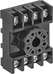 |
Relays with 1 Circuit Controlled and Knob | Relays with 2 Circuits Controlled and Knob | Sockets |
Turn machinery, such as paint and conveyor lines, on and off after a set period of time. These timer relays plug into relay sockets (sold separately) for fast installation and replacement.
Sockets—Relay sockets mount on 35 mm DIN rail (also known as DIN 3) or flat surfaces.
Timer Relays | Sockets | ||||||||||||||
|---|---|---|---|---|---|---|---|---|---|---|---|---|---|---|---|
Timing Range | Switching Current, amp | ||||||||||||||
No. of Terminals | Input Voltage | Control Current, mA | No. of | Overall | @ 240 V AC | @ 24 V DC | Max. Switching Voltage | hp @ Switching Voltage | Timing Adjustment Style | Each | Each | ||||
Delayed Start (Delay on Make) | |||||||||||||||
2 Circuits Controlled with 2 Off or 2 On—DPDT | |||||||||||||||
| 8 | 24V AC, 24V DC | 83 | 1 | 0.1 sec. to 10 sec. | 10 | 8 | 240V AC/30V DC | 1/3 hp @ 240V AC | Knob | 7268K32 | 000000 | 7122K19 | 00000 | ||
| 8 | 24V AC, 24V DC | 83 | 1 | 0.6 sec. to 60 sec. | 10 | 8 | 240V AC/30V DC | 1/3 hp @ 240V AC | Knob | 7268K34 | 00000 | 7122K19 | 0000 | ||
| 8 | 120V AC, 120V DC | 17 | 1 | 0.05 sec. to 1 sec. | 10 | 8 | 240V AC/30V DC | 1/3 hp @ 240V AC | Knob | 7268K21 | 00000 | 7122K19 | 0000 | ||
| 8 | 120V AC, 120V DC | 17 | 1 | 0.1 sec. to 10 sec. | 10 | 8 | 240V AC/30V DC | 1/3 hp @ 240V AC | Knob | 7268K23 | 00000 | 7122K19 | 0000 | ||
| 8 | 120V AC, 120V DC | 17 | 1 | 0.3 sec. to 30 sec. | 10 | 8 | 240V AC/30V DC | 1/3 hp @ 240V AC | Knob | 7268K24 | 00000 | 7122K19 | 0000 | ||
| 8 | 120V AC, 120V DC | 17 | 1 | 0.6 sec. to 60 sec. | 10 | 8 | 240V AC/30V DC | 1/3 hp @ 240V AC | Knob | 7268K25 | 00000 | 7122K19 | 0000 | ||
| 8 | 120V AC, 120V DC | 17 | 1 | 1.8 sec. to 180 sec. | 10 | 8 | 240V AC/30V DC | 1/3 hp @ 240V AC | Knob | 7268K26 | 00000 | 7122K19 | 0000 | ||
| 8 | 120V AC, 120V DC | 17 | 1 | 3 sec. to 300 sec. | 10 | 8 | 240V AC/30V DC | 1/3 hp @ 240V AC | Knob | 7268K51 | 00000 | 7122K19 | 0000 | ||
| 8 | 120V AC, 120V DC | 17 | 1 | 0.1 min. to 10 min. | 10 | 8 | 240V AC/30V DC | 1/3 hp @ 240V AC | Knob | 7268K52 | 00000 | 7122K19 | 0000 | ||
| 8 | 120V AC, 120V DC | 17 | 1 | 0.6 min. to 60 min. | 10 | 8 | 240V AC/30V DC | 1/3 hp @ 240V AC | Knob | 7268K54 | 00000 | 7122K19 | 0000 | ||
| 8 | 12V DC | 170 | 1 | 0.1 sec. to 10 sec. | 10 | 8 | 240V AC/30V DC | 1/3 hp @ 240V AC | Knob | 7268K91 | 00000 | 7122K19 | 0000 | ||
| 8 | 12V DC | 170 | 1 | 0.6 sec. to 60 sec. | 10 | 8 | 240V AC/30V DC | 1/3 hp @ 240V AC | Knob | 7268K92 | 00000 | 7122K19 | 0000 | ||
Delayed Switch Off (Delay on Break) | |||||||||||||||
2 Circuits Controlled with 2 Off or 2 On—DPDT | |||||||||||||||
| 11 | 24V AC, 24V DC | 83 | 1 | 0.1 sec. to 10 sec. | 10 | 8 | 240V AC/30V DC | 1/3 hp @ 240V AC | Knob | 7268K72 | 00000 | 7122K21 | 0000 | ||
| 11 | 24V AC, 24V DC | 83 | 1 | 0.6 sec. to 60 sec. | 10 | 8 | 240V AC/30V DC | 1/3 hp @ 240V AC | Knob | 7268K74 | 00000 | 7122K21 | 0000 | ||
| 11 | 24V AC, 24V DC | 83 | 1 | 0.6 min. to 60 min. | 10 | 8 | 240V AC/30V DC | 1/3 hp @ 240V AC | Knob | 7268K77 | 00000 | 7122K21 | 0000 | ||
| 11 | 120V AC, 120V DC | 17 | 1 | 0.05 sec. to 5 sec. | 10 | 8 | 240V AC/30V DC | 1/3 hp @ 240V AC | Knob | 7268K42 | 00000 | 7122K21 | 0000 | ||
| 11 | 120V AC, 120V DC | 17 | 1 | 0.1 sec. to 10 sec. | 10 | 8 | 240V AC/30V DC | 1/3 hp @ 240V AC | Knob | 7268K43 | 00000 | 7122K21 | 0000 | ||
| 11 | 120V AC, 120V DC | 17 | 1 | 0.3 sec. to 30 sec. | 10 | 8 | 240V AC/30V DC | 1/3 hp @ 240V AC | Knob | 7268K44 | 00000 | 7122K21 | 0000 | ||
| 11 | 120V AC, 120V DC | 17 | 1 | 0.6 sec. to 60 sec. | 10 | 8 | 240V AC/30V DC | 1/3 hp @ 240V AC | Knob | 7268K45 | 00000 | 7122K21 | 0000 | ||
| 11 | 120V AC, 120V DC | 17 | 1 | 1.2 sec. to 120 sec. | 10 | 8 | 240V AC/30V DC | 1/3 hp @ 240V AC | Knob | 7268K4 | 00000 | 7122K21 | 0000 | ||
| 11 | 120V AC, 120V DC | 17 | 1 | 1.8 sec. to 180 sec. | 10 | 8 | 240V AC/30V DC | 1/3 hp @ 240V AC | Knob | 7268K46 | 00000 | 7122K21 | 0000 | ||
| 11 | 120V AC, 120V DC | 17 | 1 | 3 sec. to 300 sec. | 10 | 8 | 240V AC/30V DC | 1/3 hp @ 240V AC | Knob | 7268K61 | 00000 | 7122K21 | 0000 | ||
| 11 | 120V AC, 120V DC | 17 | 1 | 0.1 min. to 10 min. | 10 | 8 | 240V AC/30V DC | 1/3 hp @ 240V AC | Knob | 7268K62 | 00000 | 7122K21 | 0000 | ||
| 11 | 120V AC, 120V DC | 17 | 1 | 0.6 min. to 60 min. | 10 | 8 | 240V AC/30V DC | 1/3 hp @ 240V AC | Knob | 7268K64 | 00000 | 7122K21 | 0000 | ||
Delayed Off | |||||||||||||||
2 Circuits Controlled with 2 Off or 2 On—DPDT | |||||||||||||||
| 8 | 24V AC, 24V DC | 100 | 8 | 0.05 sec. to 1,800 sec. | 10 | 8 | 240V AC/30V DC | 1/3 hp @ 240V AC | Knob | 7268K48 | 00000 | 7122K19 | 0000 | ||
| 8 | 120V AC, 120V DC | 20 | 8 | 0.05 sec. to 1,800 sec. | 10 | 8 | 240V AC/30V DC | 1/3 hp @ 240V AC | Knob | 7268K47 | 00000 | 7122K19 | 0000 | ||
Interval | |||||||||||||||
2 Circuits Controlled with 2 Off or 2 On—DPDT | |||||||||||||||
| 8 | 120V AC, 120V DC | 17 | 1 | 0.05 sec. to 5 sec. | 10 | 8 | 240V AC/30V DC | 1/3 hp @ 240V AC | Knob | 7630K31 | 00000 | 7122K19 | 0000 | ||
| 8 | 120V AC, 120V DC | 17 | 1 | 0.6 sec. to 60 sec. | 10 | 8 | 240V AC/30V DC | 1/3 hp @ 240V AC | Knob | 7630K32 | 00000 | 7122K19 | 0000 | ||
| 8 | 120V AC, 120V DC | 17 | 1 | 0.1 min. to 10 min. | 10 | 8 | 240V AC/30V DC | 1/3 hp @ 240V AC | Knob | 7630K33 | 00000 | 7122K19 | 0000 | ||
| 8 | 120V AC, 120V DC | 17 | 1 | 0.6 min. to 60 min. | 10 | 8 | 240V AC/30V DC | 1/3 hp @ 240V AC | Knob | 7630K34 | 00000 | 7122K19 | 0000 | ||
Repeat Cycle | |||||||||||||||
2 Circuits Controlled with 2 Off or 2 On—DPDT | |||||||||||||||
| 8 | 24V AC, 24V DC | 83 | 1 | 0.1 sec. to 10 sec. | 10 | 8 | 240V AC/30V DC | 1/3 hp @ 240V AC | Knob | 7630K81 | 000000 | 7122K19 | 0000 | ||
| 8 | 24V AC, 24V DC | 83 | 1 | 0.6 sec. to 60 sec. | 10 | 8 | 240V AC/30V DC | 1/3 hp @ 240V AC | Knob | 7630K83 | 000000 | 7122K19 | 0000 | ||
| 8 | 24V AC, 24V DC | 83 | 1 | 1.8 sec. to 180 sec. | 10 | 8 | 240V AC/30V DC | 1/3 hp @ 240V AC | Knob | 7630K85 | 000000 | 7122K19 | 0000 | ||
| 8 | 120V AC, 120V DC | 17 | 1 | 0.05 sec. to 5 sec. | 10 | 8 | 240V AC/30V DC | 1/3 hp @ 240V AC | Knob | 7630K11 | 000000 | 7122K19 | 0000 | ||
| 8 | 120V AC, 120V DC | 17 | 1 | 0.1 sec. to 10 sec. | 10 | 8 | 240V AC/30V DC | 1/3 hp @ 240V AC | Knob | 7630K12 | 000000 | 7122K19 | 0000 | ||
| 8 | 120V AC, 120V DC | 17 | 1 | 0.6 sec. to 60 sec. | 10 | 8 | 240V AC/30V DC | 1/3 hp @ 240V AC | Knob | 7630K14 | 000000 | 7122K19 | 0000 | ||
| 8 | 120V AC, 120V DC | 17 | 1 | 1.8 sec. to 180 sec. | 10 | 8 | 240V AC/30V DC | 1/3 hp @ 240V AC | Knob | 7630K16 | 000000 | 7122K19 | 0000 | ||
| 8 | 120V AC, 120V DC | 17 | 1 | 3 sec. to 300 sec. | 10 | 8 | 240V AC/30V DC | 1/3 hp @ 240V AC | Knob | 7630K17 | 000000 | 7122K19 | 0000 | ||
| 8 | 120V AC, 120V DC | 17 | 1 | 0.1 min. to 10 min. | 10 | 8 | 240V AC/30V DC | 1/3 hp @ 240V AC | Knob | 7630K18 | 000000 | 7122K19 | 0000 | ||
| 8 | 120V AC, 120V DC | 17 | 1 | 0.3 min. to 30 min. | 10 | 8 | 240V AC/30V DC | 1/3 hp @ 240V AC | Knob | 7630K23 | 000000 | 7122K19 | 0000 | ||
| 8 | 12V DC | 170 | 1 | 1.8 sec. to 180 sec. | 10 | 8 | 240V AC/30V DC | 1/3 hp @ 240V AC | Knob | 7630K59 | 00000 | 7122K19 | 0000 | ||
Switch on (Single Shot) | |||||||||||||||
1 Circuit Controlled with 1 Off or 1 On—SPDT | |||||||||||||||
| 8 | 120V AC, 120V DC | 17 | 1 | 0.1 sec. to 10 sec. | 10 | 8 | 240V AC/30V DC | 1/3 hp @ 240V AC | Knob | 7630K41 | 00000 | 7122K19 | 0000 | ||
| 8 | 120V AC, 120V DC | 17 | 1 | 0.6 sec. to 60 sec. | 10 | 8 | 240V AC/30V DC | 1/3 hp @ 240V AC | Knob | 7630K42 | 00000 | 7122K19 | 0000 | ||
DIN-Rail Mount Multifunction Timer Relays
Timer Relays with Delayed, Interval, Switch On, and Repeat Cycles
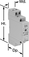 |
1 Circuit Controlled |
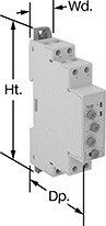 |
2 Circuits Controlled |
Timer relays with delayed, interval, switch-on, and repeat cycles have a broad range of applications. Use them to precisely control machines such as conveyors, lighting systems, and electric motors.
Delayed Start (Delay on Make) Timer—This function allows you to set how long it takes for the relay to turn on after input voltage is applied. For example, a drill starts pumping lubricant immediately, but it does not start rotating until the set time has elapsed.
Delayed Switch Off (Delay on Break) Timer—This function uses a switch instead of input voltage. When the switch is turned off, the relay remains on for a programmed amount of time before turning off. For example, a projector’s light is turned off with a switch, but its cooling fan continues to run for a set time.
Delayed Switch-On with Delayed Switch-Off Timer—This function uses a switch instead of input voltage. It allows you to set how long the relay takes to turn on after a switch is turned on, and how long it will stay on after the switch is turned off. For example, a furnace turns on, but the fan doesn’t start pushing air through the vents until it has been heated. When the furnace turns off, the fan keeps blowing to circulate all the hot air.
Delayed-Pulse Timer—This function uses input voltage to turn on the relay for a brief period after a preset time. For example, a light flashes a few seconds after a door closes.
Interval Timer—This function uses input voltage to turn on the relay for a programmed amount of time. For example, when a part moving down a conveyor reaches a certain location, a cleaning spray comes on for a set time.
Interval Switch-Off Timer—This function requires a switch to activate the relay, which stays off for the programmed amount of time. For example, lights in a storage room are turned on with a switch and stay on for a set time before turning off.
Switch on (Single Shot) Timer—This function requires a switch to activate the relay, which stays on for the programmed amount of time. For example, lights in a storage room are turned on with a switch and stay on for a set time before turning off.
Repeat-Cycle Timer—This function starts with an on cycle and then alternates between an on cycle and off cycle of equal durations until input voltage is removed. A common example would be a flashing light.
Start-Off Repeat Cycle Timer—This function starts with an off cycle and alternates between an on cycle and off cycle of equal durations until input voltage is removed. A common example would be a flashing light.
Switch Fixed On/Off Timer—This function requires a switch to activate the timing function instead of the input voltage (which is applied the entire time). It keeps the relay on whenever the switch is closed; it will only turn off if the switch is open.
Timing Range | ||||||||||||||
|---|---|---|---|---|---|---|---|---|---|---|---|---|---|---|
No. of Terminals | Input Voltage | Control Current, mA | Timer Relay Function | No. of | Overall | Switching Current @ Voltage | Max. Switching Voltage, V AC | Ht. | Wd. | Dp. | Each | |||
1 Circuit Controlled with 1 Off or 1 On—SPDT | ||||||||||||||
| 8 | 12V AC, 24V AC, 48V AC, 120V AC, 240V AC, 12V DC, 24V DC, 48V DC, 60V DC, 120V DC, 240V DC | 6 | Delayed Start (Delay on Make) Delayed Switch Off (Delay on Break) Delayed Switch-On with Delayed Switch-Off Delayed Pulse Interval Interval Switch-Off Switch on (Single Shot) Repeat Cycle Start-Off Repeat Cycle Switch Fixed On/Off | 8 | 0.1 sec. to 10 day | 8 amp @ 240V AC | 250 | 4.1" | 0.7" | 2.6" | 6964K102 | 000000 | ||
2 Circuits Controlled with 2 Off or 2 On—DPDT | ||||||||||||||
| 8 | 12V AC, 24V AC, 48V AC, 120V AC, 240V AC, 12V DC, 24V DC, 48V DC, 60V DC, 120V DC, 240V DC | 7 | Delayed Start (Delay on Make) Delayed Switch Off (Delay on Break) Delayed Switch-On with Delayed Switch-Off Delayed Pulse Interval Interval Switch-Off Switch on (Single Shot) Repeat Cycle Start-Off Repeat Cycle Switch Fixed On/Off | 8 | 0.1 sec. to 10 day | 8 amp @ 240V AC | 250 | 4.1" | 0.7" | 2.6" | 6964K103 | 000000 | ||
Smart Multifunction Monitoring Relays
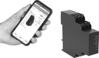 |
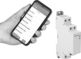
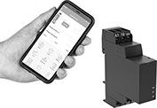
Remotely control these relays through an app on your smartphone—they simultaneously monitor phase, voltage, and frequency. The downloadable app lets you change the tripping range, modify settings, and save programs to apply to multiple relays. Tap your smartphone or tablet to the relays to connect to them. They use NFC (near field communication), so you don’t need to manually pair them like Bluetooth devices.
You’ll often see these relays used to protect motors, generators, and other three-phase circuits from burning out or overheating. They'll switch the circuit off if they detect voltage or frequencies outside of the set range or phase loss, imbalance, or reversal. You can see that they're wired correctly and when they're actuated based on the LED indicators. Rated IP20, they have recessed terminals that keep fingers and other objects from touching live circuits. Mount them on a 35 mm DIN rail (also known as DIN 3 rail) for fast installation.
No. of Terminals | Input Voltage, V AC | Trip Voltage, V AC | Input Freq., Hz | Trip Freq., Hz | Trip Time, sec. | Reset Type | Switching Current @ Voltage | Max. Switching Voltage, V AC | Ht. | Wd. | Dp. | Operating System Compatibility | Each | |||
|---|---|---|---|---|---|---|---|---|---|---|---|---|---|---|---|---|
2 Circuits Controlled with 2 Off or 2 On—DPDT | ||||||||||||||||
With Screw Terminals | ||||||||||||||||
| 12 | 208, 240, 300, 480 | 208 to 480 | 50, 60 | 45 to 66 | 0.1 to 60 | Automatic | 8 amp @ 240V AC | 250 | 3.5" | 0.9" | 3.9" | Android 7.0 or Later, iOS 14.5 or Later | 8452N11 | 0000000 | ||
Hazardous Location Relays
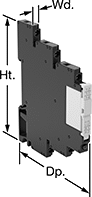 |
Screw Terminals |
Sealed for safety, these relays are a good choice for hazardous locations where combustible or corrosive gases may be present.
Screw Terminals—Relays with screw terminals are considered interface relays, so they’re placed between your controller and components to isolate the input and output circuits. This means they protect your component from voltage spikes while amplifying the relay’s signal and reducing interference for reliable transmission. They are often used for switching applications, such as small motors and pilot lights. The included relay socket mounts on 35 mm DIN rail (also known as DIN 3 rail).
No. of Terminals | Input Voltage | Control Current, mA | Switching Current @ Voltage | Max. Switching Voltage | Ht. | Wd. | Dp. | Enclosure Rating | Hazardous Location Rating | Each | |||
|---|---|---|---|---|---|---|---|---|---|---|---|---|---|
Screw Terminals | |||||||||||||
2 Circuits Controlled with 2 Off or 2 On—DPDT | |||||||||||||
| 8 | 24V AC, 24V DC | 13.5 | 8 amp @ 240V AC/24V DC | 400V AC/300V DC | 3.5" | 0.6" | 2.9" | IP20 | NEC Class I Division 2 Groups A, B, C, D | 4190N16 | 000000 | ||
| 8 | 48V AC, 48V DC | 4 | 8 amp @ 240V AC/24V DC | 400V AC/300V DC | 3.5" | 0.6" | 2.9" | IP20 | NEC Class I Division 2 Groups A, B, C, D | 4190N18 | 00000 | ||
| 8 | 120V AC, 120V DC | 3.5 | 8 amp @ 240V AC/24V DC | 400V AC/300V DC | 3.5" | 0.6" | 2.9" | IP20 | NEC Class I Division 2 Groups A, B, C, D | 4190N21 | 00000 | ||
| 8 | 240V AC, 240V DC | 3.5 | 8 amp @ 240V AC/24V DC | 400V AC/300V DC | 3.5" | 0.6" | 2.9" | IP20 | NEC Class I Division 2 Groups A, B, C, D | 4190N23 | 00000 | ||
Circuit Board Safety Relays
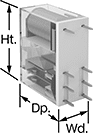 |
8 Terminals |
Reduce connection errors on circuit boards that control machine guards and other safety devices. Also known as force-guided contact relays, they have contact pairs that won’t close at the same time, even if contacts stick or weld shut. These relays take up less space on a board than those with electrical wiring because their solder pin terminals mount directly through circuit board holes. Use them to control high-power components, such as fans and heaters, from a low-power circuit.
No. of Terminals | Input Voltage, V DC | Control Current, mA | Switching Current @ Voltage | Max. Switching Voltage | Mechanical Life Cycles | Ht. | Wd. | Dp. | Pin Lg. | Features | Each | |||
|---|---|---|---|---|---|---|---|---|---|---|---|---|---|---|
2 Circuits Controlled with 2 Off or 2 On—DPDT | ||||||||||||||
| 8 | 12 | 59 | 8 amp @ 240V AC/24V DC | 250V AC, 125V DC | 10,000,000 | 1.1" | 0.5" | 1" | 0.2" | Interlocked Opposing Contacts | 6253N13 | 000000 | ||
| 8 | 24 | 29 | 8 amp @ 240V AC | 250V AC | 10,000,000 | 1.1" | 0.5" | 1" | 0.2" | Interlocked Opposing Contacts | 6253N11 | 00000 | ||
Screw Terminal Relays
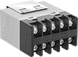 | 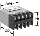 |
Use the screw terminals to hardwire these relays. The built-in enclosure protects contacts from dust and dirt. These relays accept voltage drops up to 50% of the rated voltage without switching. They’re often used with industrial automation systems, security and emergency lighting, and small motors. Also known as power relays.
No. of Terminals | Input Voltage | Control Current, mA | Switching Current @ Voltage | Max. Switching Voltage, V AC | hp @ Switching Voltage | Ht. | Wd. | Dp. | Each | |||
|---|---|---|---|---|---|---|---|---|---|---|---|---|
4 Circuits Controlled with 2 Off and 2 On—4PST-2NO/2NC | ||||||||||||
Surface Mount | ||||||||||||
| 10 | 120V AC | 22 | 25 amp @ 240V AC/24V DC (Off Circuit Position) 8 amp @ 240V AC/24V DC (On Circuit Position) | 250 | 1 1/2 hp @ 120V AC 3 hp @ 240V AC 3 hp @ 277V AC | 1.4" | 2" | 2.5" | 7105K15 | 000000 | ||
| 10 | 24V DC | 83 | 25 amp @ 240V AC/24V DC (Off Circuit Position) 8 amp @ 240V AC/24V DC (On Circuit Position) | 250 | 1 1/2 hp @ 120V AC 3 hp @ 240V AC 3 hp @ 277V AC | 1.4" | 2" | 2.5" | 7105K19 | 00000 | ||
4 Circuits Controlled with 3 Off and 1 On—4PST-3NO/1NC | ||||||||||||
Surface Mount | ||||||||||||
| 10 | 120V AC | 22 | 25 amp @ 240V AC/24V DC (Off Circuit Position) 8 amp @ 240V AC/24V DC (On Circuit Position) | 250 | 1 1/2 hp @ 120V AC 3 hp @ 240V AC 3 hp @ 277V AC | 1.4" | 2" | 2.5" | 7105K13 | 00000 | ||
| 10 | 24V DC | 83 | 25 amp @ 240V AC/24V DC (Off Circuit Position) 8 amp @ 240V AC/24V DC (On Circuit Position) | 250 | 1 1/2 hp @ 120V AC 3 hp @ 240V AC 3 hp @ 277V AC | 1.4" | 2" | 2.5" | 7105K18 | 00000 | ||
Smart DIN-Rail Mount Multifunction Timer Relays
 |  |
1 Circuit Controlled | 2 Circuits Controlled |
No. of Terminals | Input Voltage | Control Power, W | Timer Relay Function | Overall Timing Range | Switching Current @ Voltage | Max. Switching Voltage, V AC | Ht. | Wd. | Dp. | Operating System Compatibility | Features | Each | |||
|---|---|---|---|---|---|---|---|---|---|---|---|---|---|---|---|
1 Circuit Controlled with 1 Off or 1 On—SPDT | |||||||||||||||
| 8 | 12V AC, 24V AC, 48V AC, 120V AC, 240V AC, 12V DC, 24V DC, 48V DC, 60V DC, 120V DC, 240V DC | 0.15 | Manual Switch Control Fixed On/Off Switch on (Single Shot) Delayed Start (Delay on Make) Delayed Switch Off (Delay on Break) Delayed Switch-On with Delayed Switch-Off Interval Repeat Cycle Asymmetrical Repeat Cycle Switch-On Asymmetrical Repeat Cycle | 0.1 sec. to 999 day | 8 amp @ 240V AC | 250 | 4.1" | 0.7" | 2.5" | Android 5.0 or Later, iOS 14.4 or Later | LED Indicator | 8491N12 | 000000 | ||
2 Circuits Controlled with 2 Off or 2 On—DPDT | |||||||||||||||
| 9 | 24V AC, 48V AC, 120V AC, 240V AC, 24V DC, 48V DC, 60V DC, 120V DC, 240V DC | 0.6 | Manual Switch Control Fixed On/Off Switch on (Single Shot) Delayed Start (Delay on Make) Delayed Switch Off (Delay on Break) Delayed Switch-On with Delayed Switch-Off Interval Repeat Cycle Asymmetrical Repeat Cycle Switch-On Asymmetrical Repeat Cycle Star-to-Delta | 0.1 sec. to 999 hr. | 8 amp @ 240V AC | 250 | 3.5" | 0.9" | 2.9" | Android 4.4 or Later, iOS 14.5 or Later | LED Indicator | 8491N11 | 00000 | ||
Interface Safety Relays
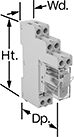 |
These relays pair the transmission reliability of an interface relay with the fail-safe operation of a safety relay. Use them to communicate signals to devices like motors or sensors. They have interlocking contacts—also known as force-guided or mechanically linked contacts—so opposing contacts won't close at the same time. This minimizes the chance of arcing, so electricity won't jump across the contacts and interfere with your relay or system. They also have an interface that isolates input and output circuits to prevent damage from voltage spikes, reduce signal interference, and amplify signal. Mount them on 35 mm DIN rail (also known as DIN 3 rail). The relays disconnect from the socket for quick replacement.
Safety Relays | Replacement Safety Relays | |||||||||||||||
|---|---|---|---|---|---|---|---|---|---|---|---|---|---|---|---|---|
No. of Terminals | Input Voltage, V DC | Control Current, mA | Switching Current @ Voltage | Max. Switching Voltage, V AC | hp @ Switching Voltage | Mechanical Life Cycles | Ht. | Wd. | Dp. | Features | Each | Each | ||||
2 Circuits Controlled with 2 Off or 2 On—DPDT | ||||||||||||||||
| 8 | 24 | 29 | 8 amp @ 240V AC | 250 | 1/2 hp @ 230V AC | 10,000,000 | 3.1" | 0.6" | 2.4" | Interlocked Opposing Contacts | 8722N11 | 000000 | 6253N11 | 000000 | ||
Circuit Board Relays
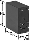 | 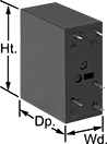 | 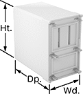 | 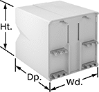 |
8 Terminals | 5 Terminals | 6 Terminals | 14 Terminals |
No. of Terminals | Input Voltage | Control Current, mA | Switching Current @ Voltage | Max. Switching Voltage, V AC | Mechanical Life Cycles | Ht. | Wd. | Dp. | Pin Lg. | Each | |||
|---|---|---|---|---|---|---|---|---|---|---|---|---|---|
Mechanical Operation | |||||||||||||
2 Circuits Controlled with 2 Off or 2 On—DPDT | |||||||||||||
| 8 | 120V AC | 8.4 | 8 amp @ 240V AC | 250 | 10,000,000 | 1.1" | 0.5" | 1" | 0.21" | 6301N12 | 00000 | ||
| 8 | 110V DC | 4.5 | 8 amp @ 240V AC | 250 | 10,000,000 | 1.1" | 0.5" | 0.6" | 0.1" | 4026N13 | 0000 | ||
Two-Hand Push-Button Safety Switches
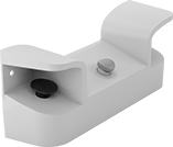 |
It takes two hands to activate these switches, minimizing the risk of accidental equipment start-up. They have an emergency stop push-button to immediately cut power. They’re rated IP65 for protection from low-pressure washdowns.
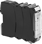
Switches with push-button actuators require a safety relay (sold separately) for a complete system.
Actuator | Mounting | |||||||||||||||
|---|---|---|---|---|---|---|---|---|---|---|---|---|---|---|---|---|
No. of Circuits Controlled | Switch Starting Position | Switch Action | Switch Designation | Material | Color | Switching Current @ Voltage | Ht. | Wd. | Dp. | No. of Holes | Hole Dia. | Fasteners Included | Features | Each | ||
| 2 | 1 Off and 1 On | Momentary | DPST-1NO/1NC | Plastic | Black | 8 amp @ 250V AC, 5 amp @ 24V DC | 7 5/16" | 18 1/2" | 5 7/16" | 2 | 29/64" | No | Emergency Stop Button | 65945K71 | 0000000 | |
 |
Input Voltage, V DC | No. of Terminals | Switching Current @ Voltage | For DIN Rail Ht., mm | Wire Connection | Features | Each | |||
|---|---|---|---|---|---|---|---|---|---|
2 Circuits Controlled with 1 Off and 1 On Switch Starting Position—DPST-1NO/1NC | |||||||||
| 24 | 12 | 5.5 amp @ 24V DC | 35 | Screw Terminal | Self-Monitoring Circuitry | 65945K72 | 0000000 | ||
Solid State Surface-Mount Timer Relays
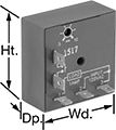 |
Attach these relays to a flat surface using the mounting hole. They have no moving parts, so compared to mechanical switches, they require less maintenance, last longer, and are quieter.
Delayed Start (Delay on Make)—Delayed start (delay on make) relays allow you to set how long it takes for the relay to turn on after input voltage is applied. For example, a drill starts pumping a lubricant immediately, but it does not start rotating until the set time has elapsed.
Timing Range | ||||||||||||
|---|---|---|---|---|---|---|---|---|---|---|---|---|
No. of Terminals | Input Voltage | Control Current, mA | No. of | Overall | Switching Current @ Voltage | Ht. | Wd. | Dp. | Each | |||
Delayed Start (Delay on Make) | ||||||||||||
1 Circuit Controlled with 1 Off or 1 On—SPDT | ||||||||||||
| 5 | 120V AC | 29 | 1 | 0.05 sec. to 1 sec. | 8 amp @ 240V AC | 2" | 2" | 0.9" | 77055K45 | 0000000 | ||
| 5 | 120V AC | 29 | 1 | 0.25 sec. to 5 sec. | 8 amp @ 240V AC | 2" | 2" | 0.9" | 77055K46 | 000000 | ||
| 5 | 120V AC | 29 | 1 | 0.5 sec. to 10 sec. | 8 amp @ 240V AC | 2" | 2" | 0.9" | 77055K47 | 000000 | ||
| 5 | 120V AC | 29 | 1 | 3 sec. to 60 sec. | 8 amp @ 240V AC | 2" | 2" | 0.9" | 77055K48 | 000000 | ||
| 5 | 120V AC | 29 | 1 | 15 sec. to 300 sec. | 8 amp @ 240V AC | 2" | 2" | 0.9" | 77055K49 | 000000 | ||
| 5 | 120V AC | 29 | 1 | 30 sec. to 10 min. | 8 amp @ 240V AC | 2" | 2" | 0.9" | 77055K51 | 000000 | ||
| 5 | 12V DC | 292 | 1 | 3 sec. to 60 sec. | 8 amp @ 240V AC | 2" | 2" | 0.9" | 77055K631 | 000000 | ||
| 5 | 12V DC | 292 | 1 | 15 sec. to 300 sec. | 8 amp @ 240V AC | 2" | 2" | 0.9" | 77055K632 | 000000 | ||
Frequency-Monitoring Relays
 |  |
DIN-Rail Mount | Relay-Socket Mount |
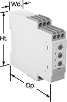
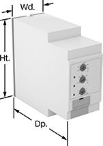
Prevent changes in frequency from damaging sensitive equipment. Often used with motors, fluorescent lighting, and controllers, these relays cut power to your device if the frequency falls outside the set range. Switches on the front of these relays let you set your trip frequency and time. You can see that they're wired correctly and when they're actuated based on the LED indicators. Rated IP20, these relays have recessed terminals that keep fingers and other objects from touching live circuits.
DIN-Rail Mount—DIN-rail mount relays snap onto 35 mm DIN rail (also known as DIN 3 rail) for fast installation.
Relay-Socket Mount—Relay-socket mount relays plug into a socket (sold separately), which is required for installation.
Monitoring Relays | Sockets | |||||||||||||||||
|---|---|---|---|---|---|---|---|---|---|---|---|---|---|---|---|---|---|---|
Trip Frequency Setting, Hz | ||||||||||||||||||
No. of Terminals | Input Voltage, V AC | 50 Hz Input | 60 Hz Input | Trip Time, sec. | Reset Type | Switching Current @ Voltage | Max. Switching Voltage | Adjustment Mechanism | Ht. | Wd. | Dp. | Features | Each | Each | ||||
1 Circuit Controlled with 1 Off or 1 On—SPDT | ||||||||||||||||||
DIN-Rail Mount | ||||||||||||||||||
| 9 | 24, 48, 120, 240 | 40 to 60 48 to 52 | 50 to 70 58 to 62 | 0.1 to 30 | Automatic, Manual | 8 amp @ 240V AC 5 amp @ 24V DC | 250V AC 24V DC | DIP Switch | 3.1" | 0.9" | 3.9" | LED Indicator | 8477N11 | 0000000 | ——— | 0 | ||
Relay-Socket Mount | ||||||||||||||||||
| 1 | 24, 48, 120, 240 | 40 to 60 48 to 52 | 50 to 70 58 to 62 | 0.1 to 30 | Automatic, Manual | 8 amp @ 240V AC 5 amp @ 24V DC | 250V AC 24V DC | DIP Switch | 3.1" | 1.4" | 3.7" | LED Indicator | 8477N12 | 000000 | 7122K12 | 000000 | ||
