


Filter by
System of Measurement
Switching Voltage
Mounting Location
Operation Type
Wire Connection
Switch Starting Position
Electrical Connection
Relay Type

Switch Action
U.S.–Mexico–Canada Agreement (USMCA) Qualifying
UL File Number
DFARS Specialty Metals
Environment
Export Control Classification Number (ECCN)
Hazardous Location Relays
 |  |
Screw Terminals | Spring-Clamp Terminals |
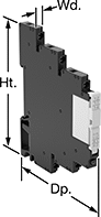
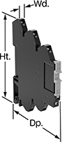
Sealed for safety, these relays are a good choice for hazardous locations where combustible or corrosive gases may be present.
Screw Terminals—Relays with screw terminals are considered interface relays, so they’re placed between your controller and components to isolate the input and output circuits. This means they protect your component from voltage spikes while amplifying the relay’s signal and reducing interference for reliable transmission. They are often used for switching applications, such as small motors and pilot lights. The included relay socket mounts on 35 mm DIN rail (also known as DIN 3 rail).
Spring-Clamp Terminals—Relays with spring-clamp terminals are considered interface relays, so they’re placed between your controller and components to isolate the input and output circuits. This means they protect your component from voltage spikes while amplifying the relay’s signal and reducing interference for reliable transmission. They are often used for switching applications, such as small motors and pilot lights. The included relay socket mounts on 35 mm DIN rail (also known as DIN 3 rail). Relays with spring-clamp terminals connect and disconnect to wires without needing to turn screws. With no screws to shake loose with vibration, the terminals hold tight over time.
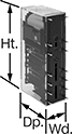
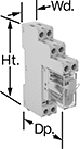
No. of Terminals | Input Voltage | Control Current, mA | Switching Current @ Voltage | Max. Switching Voltage | Ht. | Wd. | Dp. | Enclosure Rating | Hazardous Location Rating | Each | |||
|---|---|---|---|---|---|---|---|---|---|---|---|---|---|
Screw Terminals | |||||||||||||
1 Circuit Controlled with 1 Off or 1 On—SPDT | |||||||||||||
| 5 | 12V AC, 12V DC | 15.5 | 6 amp @ 240V AC/30V DC | 400V AC/125V DC | 2.9" | 0.2" | 3.5" | IP20 | NEC Class I Division 2 Groups A, B, C, D | 4190N311 | 000000 | ||
| 5 | 12V AC, 12V DC | 29 | 12 amp @ 240V AC/24V DC | 400V AC/300V DC | 2.9" | 0.6" | 3.5" | IP20 | NEC Class I Division 2 Groups A, B, C, D | 4190N312 | 00000 | ||
| 5 | 24V AC, 24V DC | 13.5 | 6 amp @ 240V AC/30V DC | 400V AC/125V DC | 3.5" | 0.2" | 2.9" | IP20 | NEC Class I Division 2 Groups A, B, C, D | 4190N11 | 00000 | ||
| 5 | 24V AC, 24V DC | 13.5 | 16 amp @ 240V AC/24V DC | 400V AC/300V DC | 3.5" | 0.6" | 2.9" | IP20 | NEC Class I Division 2 Groups A, B, C, D | 4190N15 | 00000 | ||
| 5 | 48V AC, 48V DC | 4 | 6 amp @ 240V AC/30V DC | 400V AC/125V DC | 3.5" | 0.2" | 2.9" | IP20 | NEC Class I Division 2 Groups A, B, C, D | 4190N12 | 00000 | ||
| 5 | 48V AC, 48V DC | 4 | 16 amp @ 240V AC/24V DC | 400V AC/300V DC | 3.5" | 0.6" | 2.9" | IP20 | NEC Class I Division 2 Groups A, B, C, D | 4190N17 | 00000 | ||
| 5 | 120V AC, 120V DC | 3.5 | 6 amp @ 240V AC/30V DC | 400V AC/125V DC | 3.5" | 0.2" | 2.9" | IP20 | NEC Class I Division 2 Groups A, B, C, D | 4190N13 | 00000 | ||
| 5 | 120V AC, 120V DC | 3.5 | 16 amp @ 240V AC/24V DC | 400V AC/300V DC | 3.5" | 0.6" | 2.9" | IP20 | NEC Class I Division 2 Groups A, B, C, D | 4190N19 | 00000 | ||
| 5 | 240V AC, 240V DC | 3.5 | 6 amp @ 240V AC/30V DC | 400V AC/125V DC | 3.5" | 0.2" | 2.9" | IP20 | NEC Class I Division 2 Groups A, B, C, D | 4190N14 | 00000 | ||
| 5 | 240V AC, 240V DC | 3.5 | 16 amp @ 240V AC/24V DC | 400V AC/300V DC | 3.5" | 0.6" | 2.9" | IP20 | NEC Class I Division 2 Groups A, B, C, D | 4190N22 | 00000 | ||
2 Circuits Controlled with 2 Off or 2 On—DPDT | |||||||||||||
| 8 | 24V AC, 24V DC | 13.5 | 8 amp @ 240V AC/24V DC | 400V AC/300V DC | 3.5" | 0.6" | 2.9" | IP20 | NEC Class I Division 2 Groups A, B, C, D | 4190N16 | 00000 | ||
| 8 | 48V AC, 48V DC | 4 | 8 amp @ 240V AC/24V DC | 400V AC/300V DC | 3.5" | 0.6" | 2.9" | IP20 | NEC Class I Division 2 Groups A, B, C, D | 4190N18 | 00000 | ||
| 8 | 120V AC, 120V DC | 3.5 | 8 amp @ 240V AC/24V DC | 400V AC/300V DC | 3.5" | 0.6" | 2.9" | IP20 | NEC Class I Division 2 Groups A, B, C, D | 4190N21 | 00000 | ||
| 8 | 240V AC, 240V DC | 3.5 | 8 amp @ 240V AC/24V DC | 400V AC/300V DC | 3.5" | 0.6" | 2.9" | IP20 | NEC Class I Division 2 Groups A, B, C, D | 4190N23 | 00000 | ||
Spring-Clamp Terminals | |||||||||||||
1 Circuit Controlled with 1 Off or 1 On—SPDT | |||||||||||||
| 5 | 12V AC, 12V DC | 15.5 | 6 amp @ 240V AC/30V DC | 400V AC/125V DC | 2.9" | 0.2" | 3.7" | IP20 | NEC Class I Division 2 Groups A, B, C, D | 8163N11 | 00000 | ||
| 5 | 12V AC, 12V DC | 29 | 12 amp @ 240V AC/24V DC | 400V AC/300V DC | 2.9" | 0.6" | 3.7" | IP20 | NEC Class I Division 2 Groups A, B, C, D | 8163N14 | 00000 | ||
| 5 | 24V AC, 24V DC | 13.5 | 6 amp @ 240V AC/30V DC | 400V AC/125V DC | 2.9" | 0.2" | 3.7" | IP20 | NEC Class I Division 2 Groups A, B, C, D | 8163N12 | 00000 | ||
| 5 | 24V AC, 24V DC | 20 | 12 amp @ 240V AC/24V DC | 400V AC/300V DC | 2.9" | 0.6" | 3.7" | IP20 | NEC Class I Division 2 Groups A, B, C, D | 8163N15 | 00000 | ||
| 5 | 120V AC, 120V DC | 3.5 | 6 amp @ 240V AC/30V DC | 400V AC/125V DC | 2.9" | 0.2" | 3.7" | IP20 | NEC Class I Division 2 Groups A, B, C, D | 8163N13 | 00000 | ||
| 5 | 120V AC, 120V DC | 4 | 12 amp @ 240V AC/24V DC | 400V AC/300V DC | 2.9" | 0.6" | 3.7" | IP20 | NEC Class I Division 2 Groups A, B, C, D | 8163N16 | 00000 | ||
Circuit Board Safety Relays
 |  |  |
8 Terminals | 10 Terminals | 14 Terminals |
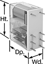
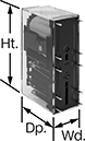
Reduce connection errors on circuit boards that control machine guards and other safety devices. Also known as force-guided contact relays, they have contact pairs that won’t close at the same time, even if contacts stick or weld shut. These relays take up less space on a board than those with electrical wiring because their solder pin terminals mount directly through circuit board holes. Use them to control high-power components, such as fans and heaters, from a low-power circuit.
Mechanical Indicator—Relays with a mechanical indicator show you whether they’re switched on or off with a flag. Peek through the window on the side to quickly check the flag’s position.
Surge Suppression Coverage—Relays with surge suppression coverage protect sensitive electronics from damage and malfunction by eliminating voltage spikes. Switching off a relay can generate surges of 300 to 500 volts, but a diode within these relays suppresses these surges. An LED indicator on these relays lights up when they’re on, so you know at a glance if they’re wired correctly.
No. of Terminals | Input Voltage, V DC | Control Current, mA | Switching Current @ Voltage | Max. Switching Voltage | Mechanical Life Cycles | Ht. | Wd. | Dp. | Pin Lg. | Features | Surge Suppression Coverage | Each | |||
|---|---|---|---|---|---|---|---|---|---|---|---|---|---|---|---|
2 Circuits Controlled with 2 Off or 2 On—DPDT | |||||||||||||||
| 8 | 24 | 29 | 3 amp @ 240V AC/24V DC | 250V AC, 125V DC | 10,000,000 | 1.1" | 0.5" | 1" | 0.16" | Interlocked Opposing Contacts, Mechanical Indicator | — | 6253N12 | 000000 | ||
4 Circuits Controlled with 2 Off and 2 On—4PST-2NO/2NC | |||||||||||||||
| 10 | 12 | 30 | 6 amp @ 240V AC/30V DC | 250V AC, 125V DC | 10,000,000 | 1.6" | 0.5" | 1" | 0.14" | Interlocked Opposing Contacts | — | 6253N15 | 00000 | ||
| 10 | 12 | 32 | 6 amp @ 240V AC/30V DC | 250V AC, 125V DC | 10,000,000 | 1.6" | 0.5" | 1" | 0.14" | Interlocked Opposing Contacts, LED Indicator | Full | 6253N25 | 00000 | ||
| 10 | 24 | 15 | 6 amp @ 240V AC/30V DC | 250V AC, 125V DC | 10,000,000 | 1.6" | 0.5" | 1" | 0.14" | Interlocked Opposing Contacts | — | 6253N14 | 00000 | ||
| 10 | 24 | 17 | 6 amp @ 240V AC/30V DC | 250V AC, 125V DC | 10,000,000 | 1.6" | 0.5" | 1" | 0.14" | Interlocked Opposing Contacts, LED Indicator | Full | 6253N26 | 00000 | ||
4 Circuits Controlled with 3 Off and 1 On—4PST-3NO/1NC | |||||||||||||||
| 10 | 12 | 30 | 6 amp @ 240V AC/30V DC | 250V AC, 125V DC | 10,000,000 | 1.6" | 0.5" | 1" | 0.14" | Interlocked Opposing Contacts | — | 6253N16 | 00000 | ||
| 10 | 12 | 32 | 6 amp @ 240V AC/30V DC | 250V AC, 125V DC | 10,000,000 | 1.6" | 0.5" | 1" | 0.14" | Interlocked Opposing Contacts, LED Indicator | Full | 6253N27 | 00000 | ||
| 10 | 24 | 15 | 6 amp @ 240V AC/30V DC | 250V AC, 125V DC | 10,000,000 | 1.6" | 0.5" | 1" | 0.14" | Interlocked Opposing Contacts | — | 6253N17 | 00000 | ||
| 10 | 24 | 17 | 6 amp @ 240V AC/30V DC | 250V AC, 125V DC | 10,000,000 | 1.6" | 0.5" | 1" | 0.14" | Interlocked Opposing Contacts, LED Indicator | Full | 6253N28 | 00000 | ||
6 Circuits Controlled with 3 Off and 3 On—6PST-3NO/3NC | |||||||||||||||
| 14 | 12 | 41 | 6 amp @ 240V AC/30V DC | 250V AC, 125V DC | 10,000,000 | 2" | 0.5" | 1" | 0.14" | Interlocked Opposing Contacts | — | 6253N18 | 00000 | ||
| 14 | 12 | 43 | 6 amp @ 240V AC/30V DC | 250V AC, 125V DC | 10,000,000 | 2" | 0.5" | 1" | 0.14" | Interlocked Opposing Contacts, LED Indicator | Full | 6253N29 | 00000 | ||
| 14 | 24 | 20 | 6 amp @ 240V AC/30V DC | 250V AC, 125V DC | 10,000,000 | 2" | 0.5" | 1" | 0.14" | Interlocked Opposing Contacts | — | 6253N19 | 00000 | ||
| 14 | 24 | 22 | 6 amp @ 240V AC/30V DC | 250V AC, 125V DC | 10,000,000 | 2" | 0.5" | 1" | 0.14" | Interlocked Opposing Contacts, LED Indicator | Full | 6253N31 | 00000 | ||
6 Circuits Controlled with 4 Off and 2 On—6PST-4NO/2NC | |||||||||||||||
| 14 | 12 | 41 | 6 amp @ 240V AC/30V DC | 250V AC, 125V DC | 10,000,000 | 2" | 0.5" | 1" | 0.14" | Interlocked Opposing Contacts | — | 6253N21 | 00000 | ||
| 14 | 12 | 43 | 6 amp @ 240V AC/30V DC | 250V AC, 125V DC | 10,000,000 | 2" | 0.5" | 1" | 0.14" | Interlocked Opposing Contacts, LED Indicator | Full | 6253N32 | 00000 | ||
| 14 | 24 | 20 | 6 amp @ 240V AC/30V DC | 250V AC, 125V DC | 10,000,000 | 2" | 0.5" | 1" | 0.14" | Interlocked Opposing Contacts | — | 6253N22 | 00000 | ||
| 14 | 24 | 22 | 6 amp @ 240V AC/30V DC | 250V AC, 125V DC | 10,000,000 | 2" | 0.5" | 1" | 0.14" | Interlocked Opposing Contacts, LED Indicator | Full | 6253N33 | 00000 | ||
6 Circuits Controlled with 5 Off and 1 On—6PST-5NO/1NC | |||||||||||||||
| 14 | 12 | 41 | 6 amp @ 240V AC/30V DC | 250V AC, 125V DC | 10,000,000 | 2" | 0.5" | 1" | 0.14" | Interlocked Opposing Contacts | — | 6253N24 | 00000 | ||
| 14 | 12 | 43 | 6 amp @ 240V AC/30V DC | 250V AC, 125V DC | 10,000,000 | 2" | 0.5" | 1" | 0.14" | Interlocked Opposing Contacts, LED Indicator | Full | 6253N34 | 00000 | ||
| 14 | 24 | 20 | 6 amp @ 240V AC/30V DC | 250V AC, 125V DC | 10,000,000 | 2" | 0.5" | 1" | 0.14" | Interlocked Opposing Contacts | — | 6253N23 | 00000 | ||
| 14 | 24 | 22 | 6 amp @ 240V AC/30V DC | 250V AC, 125V DC | 10,000,000 | 2" | 0.5" | 1" | 0.14" | Interlocked Opposing Contacts, LED Indicator | Full | 6253N35 | 00000 | ||
Interface Safety Relays
 |
These relays pair the transmission reliability of an interface relay with the fail-safe operation of a safety relay. Use them to communicate signals to devices like motors or sensors. They have interlocking contacts—also known as force-guided or mechanically linked contacts—so opposing contacts won't close at the same time. This minimizes the chance of arcing, so electricity won't jump across the contacts and interfere with your relay or system. They also have an interface that isolates input and output circuits to prevent damage from voltage spikes, reduce signal interference, and amplify signal. Mount them on 35 mm DIN rail (also known as DIN 3 rail). The relays disconnect from the socket for quick replacement.
LED Indicator—Relays with LED indicator light up when the relay is on, so you’ll know it’s wired correctly and can tell at a glance whether it’s on or off.
Safety Relays | Replacement Safety Relays | ||||||||||||||
|---|---|---|---|---|---|---|---|---|---|---|---|---|---|---|---|
No. of Terminals | Input Voltage, V DC | Control Current, mA | Switching Current @ Voltage | Max. Switching Voltage | Mechanical Life Cycles | Ht. | Wd. | Dp. | Features | Each | Each | ||||
2 Circuits Controlled with 1 Off and 1 On—DPST-1NO/1NC | |||||||||||||||
| 6 | 12 | 63 | 3 amp @ 240V AC/24V DC | 250V AC, 125V DC | 10,000,000 | 1.1" | 0.5" | 1.1" | Interlocked Opposing Contacts, LED Indicator | 8722N12 | 000000 | 8722N13 | 000000 | ||
