


Filter by
Switch Starting Position
Switch Designation
Actuator Style


Number of Circuits Controlled
Wire Connection
Switch Action
Key Included
Electrical Connection
Key Entry
Housing Material
Conduit Connection Gender
Number of Positions
DFARS Specialty Metals
Export Control Classification Number (ECCN)
Illumination
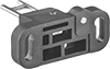
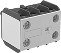
Access-Delay Frame-Mounted Safety Switches
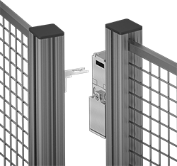 |  |
Key Shown Actuating from the Side | Style C |
Delay access to hazardous areas until conditions are safe; use these switches with machines that take time to stop after they are turned off. Mount the switch to the door frame and mount the key to the door so that the key is inserted into the switch when the door is closed. When the door is pulled, the key is held in place with 225 lbs. of force until the switch receives a signal from a time-delay relay, motion sensor, or position sensor (not included) that the machine’s motion has stopped. After the motion has stopped, the key can be removed from the switch, releasing the access door. They’re often used with machine guards. All have positive-force, normally-closed contacts that will open a circuit when the switch is actuated even if a spring fails or the contacts stick. They’re rated for protection from washdowns and temporary submersion.
Style C—Style C has a key entry on two opposite sides of the switch.
Housing | Conduit | ||||||||||||||||||
|---|---|---|---|---|---|---|---|---|---|---|---|---|---|---|---|---|---|---|---|
Style | No. of Circuits Controlled | Switch Starting Position | Switch Action | No. of Terminals | Switch Designation | Switching Current @ Voltage | Max. Voltage | Input Voltage | Holding Force, lbf | Ht. | Wd. | Dp. | Trade Size | Thread Type | Enclosure Rating | Each | |||
Screw-Terminal Wire Connection with Positive-Force Normally Closed Contacts and Rotating Head | |||||||||||||||||||
| C | 4 | 2 Off and 2 On | Maintained | 8 | 4PST-2NO/2NC | 4 amp @ 120V AC, 4 amp @ 24V DC | 240V AC 24V DC | 24V AC, 24V DC | 225 | 7.6" | 1.2" | 1.6" | 1/2 | NPT | IP67 | 7787K12 | 0000000 | ||
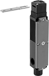
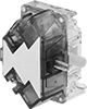
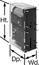
Frame-Mounted Safety Switches
|  |
Key Shown Actuating from the Side | Style H |
Also known as interlock switches, these ensure the safety of personnel by automatically shutting off power to machinery when an access door opens. Mount the switch to the door frame and mount a key to the door so that the key is inserted into the switch when the door is closed. When the door opens, the key is removed from the switch and the machine shuts down. They’re often used with machine guards for large robots.
IP67 Enclosure Rating—IP67 rated switches protect against temporary submersion.
Key Included—All switches require an actuator key, but not all include one—check whether you need to pick out a separate actuator key. For some switch styles, you can also select the mounting orientation of the key.
Housing | Conduit | |||||||||||||||||
|---|---|---|---|---|---|---|---|---|---|---|---|---|---|---|---|---|---|---|
Style | No. of Circuits Controlled | Switch Starting Position | Switch Action | No. of Terminals | Switch Designation | Switching Current @ Voltage | Max. Voltage | Ht. | Wd. | Dp. | Trade Size | Thread Type | Key Included | Enclosure Rating | Each | |||
Screw-Terminal Wire Connection with Rotating Head | ||||||||||||||||||
| H | 4 | 2 Off and 2 On | Maintained | 8 | 4PST-2NO/2NC | 2.5 amp @ 120V AC, 1 amp @ 125V DC | 120V AC 125V DC | 7.1" | 1.5" | 1.5" | 1/2 | NPT | No | IP67 | 65665K31 | 0000000 | ||
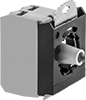
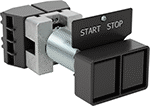
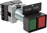
Metal 30 mm Panel-Mount Lever Switches
 |
Rated NEMA 4, 13, and IP66, these switches are protected from washdowns and oil/coolant spraying. They include enough contact blocks to control the number of circuits listed. The contact block is rated IP20.
3 Positions—Three-position switches are off in the center position.
Lever Lg. | No. of Circuits Controlled | Switch Starting Position | Switch Action | No. of Terminals | Switch Designation | Switching Current @ Voltage | Max. Voltage | Dia. | Dp. Behind Panel | For Max. No. of Contact Blocks | Actuator Color | Each | |||
|---|---|---|---|---|---|---|---|---|---|---|---|---|---|---|---|
3 Positions | |||||||||||||||
With Screw Terminals | |||||||||||||||
| 15/16" | 4 | 2 Off and 2 On | Maintained | 8 | 4PST-2NO/2NC | 6 amp @ 120V AC, 2.5 amp @ 24V DC | 600V AC 600V DC | 1 5/16" | 2 3/4" | 4 | Black | 9235K6 | 0000000 | ||
 |
Additional contact blocks can be added to control more circuits, or to replace the included contact block.
No. of Circuits Controlled | Switch Starting Position | No. of Terminals | Switch Designation | Enclosure Rating | Certification | Specs. Met | Each | ||
|---|---|---|---|---|---|---|---|---|---|
| 1 | 1 Off | 2 | SPST-NO | IP20 | CSA Certified | EN 60947-1, EN 60947-5-1, EN 60947-5-4, IEC 60947-1, IEC 60947-5-1, IEC 60947-5-4 | 9235K97 | 000000 | |
| 1 | 1 On | 2 | SPST-NC | IP20 | CSA Certified | EN 60947-1, EN 60947-5-1, EN 60947-5-4, IEC 60947-1, IEC 60947-5-1, IEC 60947-5-4 | 9235K98 | 00000 | |
| 2 | 1 Off and 1 On | 4 | DPST-1NO/1NC | IP20 | CSA Certified | EN 60947-1, EN 60947-5-1, EN 60947-5-4, IEC 60947-1, IEC 60947-5-1, IEC 60947-5-4 | 9235K99 | 00000 |
22 mm Panel-Mount Build-Your-Own Plastic Push-Button Switches
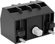
Contact Blocks with Mounting Latch
 |
Contact blocks with mounting latch accept additional contact blocks to control more circuits.
No. of Circuits Controlled | Switch Starting Position | No. of Terminals | Switch Designation | Switching Current @ Voltage | Max. Voltage | Dp. Behind Panel | Wire Connection | Enclosure Rating | Certification | Each | |||
|---|---|---|---|---|---|---|---|---|---|---|---|---|---|
| 4 | 2 Off and 2 On | 8 | 4PST-2NO/2NC | 6 amp @ 120V AC, 2.5 amp @ 24V DC | 600V AC 600V DC | 2" | Screw Terminal | IP20 | C-UL Listed, CE Marked, UL Listed | 7557K46 | 000000 | ||
 |
No. of Circuits Controlled | Switch Starting Position | No. of Terminals | Switch Designation | Switching Current @ Voltage | For Switch Manufacturer | Max. Voltage | Wire Connection | Enclosure Rating | Certification | Each | ||
|---|---|---|---|---|---|---|---|---|---|---|---|---|
| 1 | 1 Off | 2 | SPST-NO | 6 amp @ 120V AC, 2.5 amp @ 24V DC | BACO Controls | 600V AC/600V DC | Screw Terminal | IP20 | C-UL Listed, CE Marked, UL Listed | 7557K1 | 00000 |
Contact Blocks with Mounting Latch, Bulb, and Bulb Holder
 |
Contact blocks with mounting latch accept additional contact blocks to control more circuits.
No. of Circuits Controlled | Switch Starting Position | No. of Terminals | Switch Designation | Switching Current @ Voltage | Max. Voltage | Dp. Behind Panel | Wire Connection | Enclosure Rating | Certification | Choose a Bulb Voltage | Each | |||
|---|---|---|---|---|---|---|---|---|---|---|---|---|---|---|
| 4 | 2 Off and 2 On | 10 | 4PST-2NO/2NC | 6 amp @ 120V AC, 2.5 amp @ 24V DC | 600V AC 600V DC | 2 9/16" | Screw Terminal | IP20 | C-UL Listed, CE Marked, UL Listed | 24V AC/24V DC, 120V AC, 240V AC | 7557K25 | 000000 | ||
|
No. of Circuits Controlled | Switch Starting Position | No. of Terminals | Switch Designation | Switching Current @ Voltage | For Switch Manufacturer | Max. Voltage | Wire Connection | Enclosure Rating | Certification | Each | ||
|---|---|---|---|---|---|---|---|---|---|---|---|---|
| 1 | 1 Off | 2 | SPST-NO | 6 amp @ 120V AC, 2.5 amp @ 24V DC | BACO Controls | 600V AC/600V DC | Screw Terminal | IP20 | C-UL Listed, CE Marked, UL Listed | 7557K1 | 00000 |
 |
Bulb Voltage | Bulb Type | Enclosure Rating | Certification | Choose a Bulb Color | Each | ||
|---|---|---|---|---|---|---|---|
| 24V AC/24V DC | LED | IP20 | C-UL Listed, CE Marked, UL Listed | Green, Red, White, Yellow | 7557K74 | 000000 | |
| 120V AC | LED | IP20 | C-UL Listed, CE Marked, UL Listed | Green, Red, White, Yellow | 7557K75 | 00000 | |
| 240V AC | LED | IP20 | C-UL Listed, CE Marked, UL Listed | Green, Red, White, Yellow | 7557K76 | 00000 |
Safety Relays
SIL 2, PLd Max. System Safety Rating—DIN-Rail Mount
 |
Relays that meet SIL 2 are tested for applications with a probability of failure of 0.1% to 1%. They’re often used for emergency shutdowns, and fire, gas, and overpressure detection.
No. of Terminals | Input Voltage | Control Current, mA | Switching Current @ Voltage | Max. Switching Voltage, V AC | Ht. | Wd. | Dp. | Features | Each | |||
|---|---|---|---|---|---|---|---|---|---|---|---|---|
Screw-Terminal Wire Connection | ||||||||||||
4 Circuits Controlled with 2 Off and 2 On—4PST-2NO/2NC | ||||||||||||
| 12 | 120V AC | 10 | 6 amp @ 240V AC | 250 | 3.4" | 0.9" | 3.9" | Interlocked Opposing Contacts, LED Indicator, Recessed Terminals | 6242N114 | 0000000 | ||
| 12 | 24V DC | 42 | 6 amp @ 240V AC | 250 | 3.4" | 0.9" | 3.9" | Interlocked Opposing Contacts, LED Indicator, Recessed Terminals | 6242N115 | 000000 | ||
Hazardous Location 30 mm Multifunction Panel-Mount Push-Button Switches
 |  |
Black | Green/Red |
Rated NEC Classes I, II, and III, these switches have a housing that keeps fire and sparks in, so they won’t ignite gases, vapors, or dust. To save space on your panel, they can control multiple circuits. Install them in a standard panel cutout.
No. of Circuits Controlled | Switch Starting Position | No. of Buttons | Switch Action | No. of Terminals | Switch Designation | Switching Current @ Voltage | For Max. Panel Thk. | Dp. Behind Panel | For Max. No. of Contact Blocks | Enclosure Rating | Choose an Actuator Color | Each | |||
|---|---|---|---|---|---|---|---|---|---|---|---|---|---|---|---|
Metal Actuator Base with Screw-Terminal Wire Connection—Not Illuminated (600V AC/250V DC Maximum Voltage) | |||||||||||||||
Flush | |||||||||||||||
| 4 | 2 Off and 2 On | 2 | Momentary | 8 | 4PST-2NO/2NC | 10 amp @ 120V AC, 2.5 amp @ 125V DC | 1 1/2" | 3 3/4" | 4 | NEMA 4X | Black, Green/Red | 8828N14 | 0000000 | ||
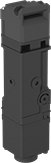
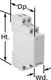
Machine-Guard Safety Relays
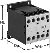 |
Relay |
The interlocked opposing contacts won't close at the same time, so these relays are suitable for safety applications such as machine guarding. The screw terminals are recessed to prevent accidental contact with live connections. Mount them on 35 mm DIN rail (also known as DIN 3 rail) or flat surfaces. These relays are built to IEC dimensional standards.
No. of Terminals | Input Voltage, V AC | Control Current, mA | Switching Current @ Voltage | Max. Switching Voltage, V AC | Mechanical Life Cycles | Ht. | Wd. | Dp. | Features | Each | |||
|---|---|---|---|---|---|---|---|---|---|---|---|---|---|
4 Circuits Controlled with 2 Off and 2 On—4PST-2NO/2NC | |||||||||||||
| 10 | 24 | 125 | 10 amp @ 600V AC | 600 | 20,000,000 | 2.3" | 1.7" | 2.2" | Interlocked Opposing Contacts, Recessed Terminals | 7230K871 | 000000 | ||
| 10 | 120 | 25 | 10 amp @ 600V AC | 600 | 20,000,000 | 2.3" | 1.7" | 2.2" | Interlocked Opposing Contacts, Recessed Terminals | 7230K872 | 00000 | ||
| 10 | 240 | 12.5 | 10 amp @ 600V AC | 600 | 20,000,000 | 2.3" | 1.7" | 2.2" | Interlocked Opposing Contacts, Recessed Terminals | 7230K873 | 00000 | ||
 |
Auxiliary Contact |
No. of Circuits Controlled | Switch Starting Position | Switch Designation | Mounting Location | For Relay Wd. | Each | ||
|---|---|---|---|---|---|---|---|
| 2 | 1 Off and 1 On | DPST-1NO/1NC | Front | 1.7" | 70255K13 | 000000 |
Circuit Board Safety Relays
 |
10 Terminals |
Reduce connection errors on circuit boards that control machine guards and other safety devices. Also known as force-guided contact relays, they have contact pairs that won’t close at the same time, even if contacts stick or weld shut. These relays take up less space on a board than those with electrical wiring because their solder pin terminals mount directly through circuit board holes. Use them to control high-power components, such as fans and heaters, from a low-power circuit.
Surge Suppression Coverage—Relays with surge suppression coverage protect sensitive electronics from damage and malfunction by eliminating voltage spikes. Switching off a relay can generate surges of 300 to 500 volts, but a diode within these relays suppresses these surges. An LED indicator on these relays lights up when they’re on, so you know at a glance if they’re wired correctly.
No. of Terminals | Input Voltage, V DC | Control Current, mA | Switching Current @ Voltage | Max. Switching Voltage | Mechanical Life Cycles | Ht. | Wd. | Dp. | Pin Lg. | Features | Surge Suppression Coverage | Each | |||
|---|---|---|---|---|---|---|---|---|---|---|---|---|---|---|---|
4 Circuits Controlled with 2 Off and 2 On—4PST-2NO/2NC | |||||||||||||||
| 10 | 12 | 30 | 6 amp @ 240V AC/30V DC | 250V AC, 125V DC | 10,000,000 | 1.6" | 0.5" | 1" | 0.14" | Interlocked Opposing Contacts | — | 6253N15 | 000000 | ||
| 10 | 12 | 32 | 6 amp @ 240V AC/30V DC | 250V AC, 125V DC | 10,000,000 | 1.6" | 0.5" | 1" | 0.14" | Interlocked Opposing Contacts, LED Indicator | Full | 6253N25 | 00000 | ||
| 10 | 24 | 15 | 6 amp @ 240V AC/30V DC | 250V AC, 125V DC | 10,000,000 | 1.6" | 0.5" | 1" | 0.14" | Interlocked Opposing Contacts | — | 6253N14 | 00000 | ||
| 10 | 24 | 17 | 6 amp @ 240V AC/30V DC | 250V AC, 125V DC | 10,000,000 | 1.6" | 0.5" | 1" | 0.14" | Interlocked Opposing Contacts, LED Indicator | Full | 6253N26 | 00000 | ||
