


Filter by
Shaft Orientation
Shaft Rotation Direction


Counting Direction
Gear Box Input Connection


Insert Material
DFARS Specialty Metals
Transmitter Type
Housing Material
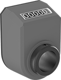
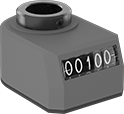
Mechanical Position Indicators
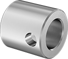
For Horizontal Shafts
 |  |
Indicator Display (1 Decimal Place) | |
 |  |
Indicator Display (2 Decimal Places) | Indicator Display (3 Decimal Places) |
Overall | |||||||||||||||
|---|---|---|---|---|---|---|---|---|---|---|---|---|---|---|---|
No. of Decimal Places | No. of Digits | Max. Counts per min. | Counts per Rev. | Resettable | Counting Direction (Shaft Rotation Direction) | Ht. | Wd. | Dp. | Housing Material | Color | Temp. Range, ° F | Each | |||
For 1/2" Diameter Shafts | |||||||||||||||
Black-Oxide Steel Insert | |||||||||||||||
| 1 | 4 | 1,500 | 1 | No | Up (Clockwise), Down (Counterclockwise) | 1.9" | 1.3" | 1.4" | Plastic | Orange | 32 to 175 | 6187N101 | 000000 | ||
| 2 | 4 | 150 | 0.1 | No | Up (Clockwise), Down (Counterclockwise) | 1.9" | 1.3" | 1.4" | Plastic | Orange | 32 to 175 | 6187N102 | 00000 | ||
| 2 | 4 | 250 | 0.5 | No | Up (Clockwise), Down (Counterclockwise) | 1.9" | 1.3" | 1.4" | Plastic | Orange | 32 to 175 | 6187N103 | 00000 | ||
| 2 | 4 | 250 | 1 | No | Up (Clockwise), Down (Counterclockwise) | 1.9" | 1.3" | 1.4" | Plastic | Orange | 32 to 175 | 6187N104 | 00000 | ||
For 3/4" Diameter Shafts | |||||||||||||||
Black-Oxide Steel Insert | |||||||||||||||
| 1 | 5 | 1,500 | 1 | No | Up (Clockwise), Down (Counterclockwise) | 2.6" | 1.9" | 1.5" | Plastic | Orange | 32 to 175 | 6187N17 | 00000 | ||
| 1 | 5 | 1,500 | 1 | No | Up (Counterclockwise), Down (Clockwise) | 2.6" | 1.9" | 1.5" | Plastic | Orange | 32 to 175 | 6187N107 | 00000 | ||
| 2 | 5 | 15 | 0.01 | No | Up (Clockwise), Down (Counterclockwise) | 2.6" | 1.9" | 1.5" | Plastic | Orange | 32 to 175 | 6187N11 | 00000 | ||
| 2 | 5 | 75 | 0.05 | No | Up (Clockwise), Down (Counterclockwise) | 2.6" | 1.9" | 1.5" | Plastic | Orange | 32 to 175 | 6187N12 | 00000 | ||
| 2 | 5 | 150 | 0.1 | No | Up (Clockwise), Down (Counterclockwise) | 2.6" | 1.9" | 1.5" | Plastic | Orange | 32 to 175 | 6187N13 | 00000 | ||
| 2 | 5 | 150 | 0.1 | No | Up (Counterclockwise), Down (Clockwise) | 2.6" | 1.9" | 1.5" | Plastic | Orange | 32 to 175 | 6187N26 | 00000 | ||
| 2 | 5 | 250 | 0.2 | No | Up (Clockwise), Down (Counterclockwise) | 2.6" | 1.9" | 1.5" | Plastic | Orange | 32 to 175 | 6187N14 | 00000 | ||
| 2 | 5 | 250 | 0.2 | No | Up (Counterclockwise), Down (Clockwise) | 2.6" | 1.9" | 1.5" | Plastic | Orange | 32 to 175 | 6187N27 | 00000 | ||
| 2 | 5 | 250 | 0.5 | No | Up (Clockwise), Down (Counterclockwise) | 2.6" | 1.9" | 1.5" | Plastic | Orange | 32 to 175 | 6187N15 | 00000 | ||
| 2 | 5 | 250 | 0.5 | No | Up (Counterclockwise), Down (Clockwise) | 2.6" | 1.9" | 1.5" | Plastic | Orange | 32 to 175 | 6187N28 | 00000 | ||
| 2 | 5 | 250 | 1 | No | Up (Clockwise), Down (Counterclockwise) | 2.6" | 1.9" | 1.5" | Plastic | Orange | 32 to 175 | 6187N16 | 00000 | ||
| 2 | 5 | 250 | 1 | No | Up (Counterclockwise), Down (Clockwise) | 2.6" | 1.9" | 1.5" | Plastic | Orange | 32 to 175 | 6187N108 | 00000 | ||
| 3 | 5 | 25 | 0.1 | No | Up (Clockwise), Down (Counterclockwise) | 2.6" | 1.9" | 1.5" | Plastic | Orange | 32 to 175 | 6187N109 | 00000 | ||
303 Stainless Steel Insert | |||||||||||||||
| 1 | 5 | 1,500 | 1 | No | Up (Clockwise), Down (Counterclockwise) | 2.6" | 1.9" | 1.5" | Plastic | Orange | 32 to 175 | 6187N114 | 000000 | ||
| 2 | 5 | 150 | 0.1 | No | Up (Clockwise), Down (Counterclockwise) | 2.6" | 1.9" | 1.5" | Plastic | Orange | 32 to 175 | 6187N115 | 000000 | ||
| 2 | 5 | 250 | 0.5 | No | Up (Clockwise), Down (Counterclockwise) | 2.6" | 1.9" | 1.5" | Plastic | Orange | 32 to 175 | 6187N116 | 000000 | ||
| 2 | 5 | 250 | 1 | No | Up (Clockwise), Down (Counterclockwise) | 2.6" | 1.9" | 1.5" | Plastic | Orange | 32 to 175 | 6187N117 | 000000 | ||
For 20 mm Diameter Shafts | |||||||||||||||
Black-Oxide Steel Insert | |||||||||||||||
| 1 | 5 | 1,500 | 1 | No | Up (Clockwise), Down (Counterclockwise) | 2.6" | 1.9" | 1.5" | Plastic | Orange | 32 to 175 | 6187N25 | 00000 | ||
| 1 | 5 | 1,500 | 1 | No | Up (Counterclockwise), Down (Clockwise) | 2.6" | 1.9" | 1.5" | Plastic | Orange | 32 to 175 | 6187N112 | 00000 | ||
| 2 | 5 | 15 | 0.01 | No | Up (Clockwise), Down (Counterclockwise) | 2.6" | 1.9" | 1.5" | Plastic | Orange | 32 to 175 | 6187N18 | 00000 | ||
| 2 | 5 | 150 | 0.1 | No | Up (Clockwise), Down (Counterclockwise) | 2.6" | 1.9" | 1.5" | Plastic | Orange | 32 to 175 | 6187N21 | 00000 | ||
| 2 | 5 | 150 | 0.1 | No | Up (Counterclockwise), Down (Clockwise) | 2.6" | 1.9" | 1.5" | Plastic | Orange | 32 to 175 | 6187N29 | 00000 | ||
| 2 | 5 | 250 | 0.2 | No | Up (Counterclockwise), Down (Clockwise) | 2.6" | 1.9" | 1.5" | Plastic | Orange | 32 to 175 | 6187N31 | 00000 | ||
| 2 | 5 | 250 | 0.5 | No | Up (Clockwise), Down (Counterclockwise) | 2.6" | 1.9" | 1.5" | Plastic | Orange | 32 to 175 | 6187N23 | 00000 | ||
| 2 | 5 | 250 | 0.5 | No | Up (Counterclockwise), Down (Clockwise) | 2.6" | 1.9" | 1.5" | Plastic | Orange | 32 to 175 | 6187N32 | 00000 | ||
| 2 | 5 | 250 | 1 | No | Up (Clockwise), Down (Counterclockwise) | 2.6" | 1.9" | 1.5" | Plastic | Orange | 32 to 175 | 6187N24 | 00000 | ||
303 Stainless Steel Insert | |||||||||||||||
| 1 | 5 | 1,500 | 1 | No | Up (Clockwise), Down (Counterclockwise) | 2.6" | 1.9" | 1.5" | Plastic | Orange | 32 to 175 | 6187N119 | 000000 | ||
 |
Black-Oxide Steel | Stainless Steel | |||||||
|---|---|---|---|---|---|---|---|---|
For Shaft Dia. | OD | Lg. | Set Screw Included | Each | Each | |||
| 1/4" | 3/4" | 3/4" | Yes | 6187N47 | 000000 | ——— | 0 | |
| 3/8" | 3/4" | 3/4" | Yes | 6187N48 | 00000 | 6187N39 | 000000 | |
| 1/2" | 3/4" | 3/4" | Yes | 6187N49 | 00000 | 6187N41 | 00000 | |
| 5/8" | 3/4" | 3/4" | Yes | 6187N51 | 00000 | 6187N42 | 00000 | |
| 12 mm | 20 mm | 20 mm | Yes | 6187N52 | 00000 | 6187N43 | 00000 | |
| 14 mm | 20 mm | 20 mm | Yes | 6187N53 | 00000 | 6187N44 | 00000 | |
| 15 mm | 20 mm | 20 mm | Yes | 6187N54 | 00000 | 6187N45 | 00000 | |
| 16 mm | 20 mm | 20 mm | Yes | 6187N55 | 00000 | 6187N46 | 00000 | |
For Vertical Shafts
 | | |
Indicator Display (1 Decimal Place) | Indicator Display (2 Decimal Places) |
Overall | |||||||||||||||
|---|---|---|---|---|---|---|---|---|---|---|---|---|---|---|---|
No. of Decimal Places | No. of Digits | Max. Counts per min. | Counts per Rev. | Resettable | Counting Direction (Shaft Rotation Direction) | Ht. | Wd. | Dp. | Housing Material | Color | Temp. Range, ° F | Each | |||
For 1/2" Diameter Shafts | |||||||||||||||
Black-Oxide Steel Insert | |||||||||||||||
| 1 | 4 | 1,500 | 1 | No | Up (Clockwise), Down (Counterclockwise) | 1.9" | 1.3" | 1.4" | Plastic | Orange | 32 to 175 | 6187N105 | 000000 | ||
| 2 | 4 | 150 | 0.1 | No | Up (Clockwise), Down (Counterclockwise) | 1.9" | 1.3" | 1.4" | Plastic | Orange | 32 to 175 | 6187N106 | 00000 | ||
For 3/4" Diameter Shafts | |||||||||||||||
Black-Oxide Steel Insert | |||||||||||||||
| 1 | 5 | 1,500 | 1 | No | Up (Clockwise), Down (Counterclockwise) | 2.6" | 1.9" | 1.5" | Plastic | Orange | 32 to 175 | 6187N111 | 00000 | ||
| 2 | 5 | 150 | 0.1 | No | Up (Clockwise), Down (Counterclockwise) | 2.6" | 1.9" | 1.5" | Plastic | Orange | 32 to 175 | 6187N33 | 00000 | ||
| 2 | 5 | 250 | 0.2 | No | Up (Clockwise), Down (Counterclockwise) | 2.6" | 1.9" | 1.5" | Plastic | Orange | 32 to 175 | 6187N34 | 00000 | ||
| 2 | 5 | 250 | 0.5 | No | Up (Clockwise), Down (Counterclockwise) | 2.6" | 1.9" | 1.5" | Plastic | Orange | 32 to 175 | 6187N35 | 00000 | ||
303 Stainless Steel Insert | |||||||||||||||
| 2 | 5 | 150 | 0.1 | No | Up (Clockwise), Down (Counterclockwise) | 2.6" | 1.9" | 1.5" | Plastic | Orange | 32 to 175 | 6187N118 | 000000 | ||
For 20 mm Diameter Shafts | |||||||||||||||
Black-Oxide Steel Insert | |||||||||||||||
| 1 | 5 | 1,500 | 1 | No | Up (Clockwise), Down (Counterclockwise) | 2.6" | 1.9" | 1.5" | Plastic | Orange | 32 to 175 | 6187N113 | 00000 | ||
| 2 | 5 | 150 | 0.1 | No | Up (Clockwise), Down (Counterclockwise) | 2.6" | 1.9" | 1.5" | Plastic | Orange | 32 to 175 | 6187N36 | 00000 | ||
| 2 | 5 | 250 | 0.2 | No | Up (Clockwise), Down (Counterclockwise) | 2.6" | 1.9" | 1.5" | Plastic | Orange | 32 to 175 | 6187N37 | 00000 | ||
| 2 | 5 | 250 | 0.5 | No | Up (Clockwise), Down (Counterclockwise) | 2.6" | 1.9" | 1.5" | Plastic | Orange | 32 to 175 | 6187N38 | 00000 | ||
|
Black-Oxide Steel | Stainless Steel | |||||||
|---|---|---|---|---|---|---|---|---|
For Shaft Dia. | OD | Lg. | Set Screw Included | Each | Each | |||
| 1/4" | 3/4" | 3/4" | Yes | 6187N47 | 000000 | ——— | 0 | |
| 3/8" | 3/4" | 3/4" | Yes | 6187N48 | 00000 | 6187N39 | 000000 | |
| 1/2" | 3/4" | 3/4" | Yes | 6187N49 | 00000 | 6187N41 | 00000 | |
| 5/8" | 3/4" | 3/4" | Yes | 6187N51 | 00000 | 6187N42 | 00000 | |
| 12 mm | 20 mm | 20 mm | Yes | 6187N52 | 00000 | 6187N43 | 00000 | |
| 14 mm | 20 mm | 20 mm | Yes | 6187N53 | 00000 | 6187N44 | 00000 | |
| 15 mm | 20 mm | 20 mm | Yes | 6187N54 | 00000 | 6187N45 | 00000 | |
| 16 mm | 20 mm | 20 mm | Yes | 6187N55 | 00000 | 6187N46 | 00000 | |
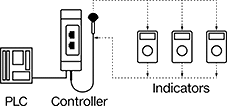
Digital Position Indicators with Wireless Transmitters
 |
Components Sold Separately |
 |
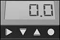 |
Indicator Display |
Send the real-time position of machine parts moving along spindles, lead screws, and threaded shafts to your computer or programmable logic controller (PLC). These indicators help you make faster, more precise adjustments than you can with standard position indicators. They have built-in transmitters that wirelessly exchange data with a controller (sold separately) plugged into your computer or PLC up to 100 ft. away. These indicators save time and help prevent errors on packaging lines and other processes that you regularly adapt for diverse products. When it’s time to reposition a component, set the new target position on your computer or PLC, and the controller will relay it to these indicators.
More customizable than standard indicators, these digital indicators have programmable features that help you adapt them to your application. You can use these indicators as either a reference point or a true measure of distance. To measure distance, match the indicator’s count per revolution to your lead screw’s threads per inch or thread pitch. You can adjust them to count from their original position or from their most recent stopping point, which is useful for repeating moves. They also have settings to work with clockwise and counterclockwise rotation, as well as vertical and horizontal shafts.
Rated IP67, all are sealed against dust and water, even if briefly submerged.
Controllers (sold separately) are required.
Overall | For 3/4" Diameter Shafts | For 20 mm Diameter Shafts | ||||||||||||||||
|---|---|---|---|---|---|---|---|---|---|---|---|---|---|---|---|---|---|---|
No. of Digits | Max. Rotation Speed, rpm | Resettable | Counting Direction (Shaft Rotation Direction) | Ht. | Wd. | Dp. | Housing Material | Color | Batteries Included | Temp. Range, ° F | Enclosure Rating | Specs. Met | Each | Each | ||||
For Horizontal and Vertical Shafts | ||||||||||||||||||
| 6 | 1,000 | Yes | Up and Down (Clockwise and Counterclockwise) | 2.9" | 1.9" | 1.6" | Plastic | Orange | Yes | 32 to 120 | IP67 | IEC 61326-1 | 6194N11 | 0000000 | ——— | 0 | ||
| 6 | 1,000 | Yes | Up and Down (Clockwise and Counterclockwise) | 2.9" | 1.9" | 1.6" | Plastic | Orange | Yes | 32 to 120 | IP67 | 2014/53/EU | ——— | 0 | 6194N12 | 0000000 | ||
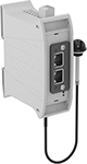 |
Controllers can be used with up to 36 position indicators.
Input | Output | |||||||||||||
|---|---|---|---|---|---|---|---|---|---|---|---|---|---|---|
Control Communication Protocol | Communication Interface | Communication Range, ft. | No. of Indicators Controlled | Total No. of RJ45 Connections | Signal Type | Voltage, V DC | Signal Type | Current, amp | Operating Voltage, V DC | Specs. Met | Each | |||
DIN-Rail Mount | ||||||||||||||
| EtherNet/IP | — | 95 | 36 | 2 | Digital | 24 | Digital | 0.05 | 24 | 2014/30/EU, IEC 61326-1 | 6194N13 | 000000000 | ||
| Modbus TCP/IP | — | 95 | 36 | 2 | Digital | 24 | Digital | 0.05 | 24 | 2014/30/EU, IEC 61326-1 | 6194N15 | 00000000 | ||
| — | PROFINET IO | 95 | 36 | 2 | Digital | 24 | Digital | 0.05 | 24 | 2014/30/EU, IEC 61326-1 | 6194N14 | 00000000 | ||
|
Black-Oxide Steel | Stainless Steel | |||||||
|---|---|---|---|---|---|---|---|---|
For Shaft Dia. | OD | Lg. | Set Screw Included | Each | Each | |||
| 1/4" | 3/4" | 3/4" | Yes | 6187N47 | 000000 | ——— | 0 | |
| 3/8" | 3/4" | 3/4" | Yes | 6187N48 | 00000 | 6187N39 | 000000 | |
| 1/2" | 3/4" | 3/4" | Yes | 6187N49 | 00000 | 6187N41 | 00000 | |
| 5/8" | 3/4" | 3/4" | Yes | 6187N51 | 00000 | 6187N42 | 00000 | |
| 12 mm | 20 mm | 20 mm | Yes | 6187N52 | 00000 | 6187N43 | 00000 | |
| 14 mm | 20 mm | 20 mm | Yes | 6187N53 | 00000 | 6187N44 | 00000 | |
| 15 mm | 20 mm | 20 mm | Yes | 6187N54 | 00000 | 6187N45 | 00000 | |
| 16 mm | 20 mm | 20 mm | Yes | 6187N55 | 00000 | 6187N46 | 00000 | |
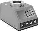
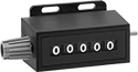
Digital Position Indicators
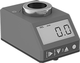 | 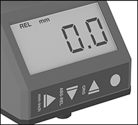 |
Indicator Display |
More customizable than standard indicators, these digital indicators have programmable features that help you adapt them to your application. Like other indicators, they track your machine component as it moves along a rotating spindle, lead screw, or other threaded shaft, which helps you adjust machinery with speed and precision. This saves time and prevents errors on process lines that you constantly adapt for different products, such as packaging lines.
Program the number you want added per revolution—you can use these indicators as a reference point or as a true measure of distance. To measure distance, match the indicator’s count per revolution to your lead screw’s threads per inch or thread pitch. You can adjust them to count from their original position or from their most recent stopping point, which is useful for repeating moves. They also have settings to work with clockwise and counterclockwise rotation, as well as vertical and horizontal shafts.
Rated IP67, all are sealed against dust and water, even if briefly submerged. They meet IEC 61326-1, which is an international standard for electromagnetic immunity and emissions.
Overall | For 1/2" Diameter Shafts | For 3/4" Diameter Shafts | For 20 mm Diameter Shafts | ||||||||||||||||||
|---|---|---|---|---|---|---|---|---|---|---|---|---|---|---|---|---|---|---|---|---|---|
No. of Digits | Max. Rotation Speed, rpm | Resettable | Counting Direction (Shaft Rotation Direction) | Ht. | Wd. | Dp. | Housing Material | Color | Batteries Included | Temp. Range, ° F | Digital Display Type | Enclosure Rating | Specs. Met | Each | Each | Each | |||||
For Horizontal and Vertical Shafts | |||||||||||||||||||||
| 5 | 1,000 | Yes | Up and Down (Clockwise and Counterclockwise) | 2.2" | 1.4" | 1.4" | Plastic | Orange | Yes | 32 to 120 | LCD | IP67 | IEC 61326-1 | 6073N18 | 0000000 | ——— | 0 | ——— | 0 | ||
| 6 | 1,000 | Yes | Up and Down (Clockwise and Counterclockwise) | 2.9" | 1.9" | 1.6" | Plastic | Orange | Yes | 32 to 120 | LCD | IP67 | IEC 61326-1 | ——— | 0 | 6073N11 | 0000000 | 6073N12 | 0000000 | ||
|
Black-Oxide Steel | Stainless Steel | |||||||
|---|---|---|---|---|---|---|---|---|
For Shaft Dia. | OD | Lg. | Set Screw Included | Each | Each | |||
| 1/4" | 3/4" | 3/4" | Yes | 6187N47 | 000000 | ——— | 0 | |
| 3/8" | 3/4" | 3/4" | Yes | 6187N48 | 00000 | 6187N39 | 000000 | |
| 1/2" | 3/4" | 3/4" | Yes | 6187N49 | 00000 | 6187N41 | 00000 | |
| 5/8" | 3/4" | 3/4" | Yes | 6187N51 | 00000 | 6187N42 | 00000 | |
| 12 mm | 20 mm | 20 mm | Yes | 6187N52 | 00000 | 6187N43 | 00000 | |
| 14 mm | 20 mm | 20 mm | Yes | 6187N53 | 00000 | 6187N44 | 00000 | |
| 15 mm | 20 mm | 20 mm | Yes | 6187N54 | 00000 | 6187N45 | 00000 | |
| 16 mm | 20 mm | 20 mm | Yes | 6187N55 | 00000 | 6187N46 | 00000 | |
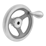
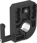
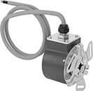
Rotary Encoder Kits
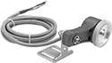 |  |
Shown with Wheel (Sold Separately) |
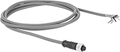
In addition to a transmitter, these kits include a 6 1/2-ft. cable and a mounting bracket. Also known as encoders, transmitters convert motion to an electrical signal to indicate distance, direction, and speed in process control and metering applications. These kits are commonly used to monitor the position or velocity of rotating equipment. You can also mount a wheel (not included) to measure distance in linear applications. Transmitters must be used with a controller that has quadrature detection to get a 4X resolution increase. Output channel Z is also known as an index channel.
Use a flexible shaft coupling (not included) to connect the transmitter shaft to a drive shaft.
For Counter Function | Encoder Output Channel | Resolution Increase | For Max. Shaft Speed, rpm | Input Voltage, V DC | Output Current, mA | Resistor Included | Body Material | Shaft Material | Fasteners Included | Fasteners Req. | For Mounting Screw Size | Choose a Resolution | Each | |||
|---|---|---|---|---|---|---|---|---|---|---|---|---|---|---|---|---|
Quadrature with Index Output Channel | ||||||||||||||||
| Up and Down | A, B, Z | 2X, 4X | 6,000 | 5 to 28 | 20 | No | Plastic | Stainless Steel | No | Yes | 1/4" | 500, 600, 1,000, 1,800, 2,500 | 16695T57 | 0000000 | ||
Rotating-Shaft-Actuated Counters
 |  |
Screw On 1 Shaft | Screw On 2 Shafts |
Shaft | Overall | ||||||||||||||
|---|---|---|---|---|---|---|---|---|---|---|---|---|---|---|---|
Resettable | No. of Digits | Max. Counts per min. | Counts per Rev. | No. of Shafts | Shaft Location | Counting Direction (Shaft Rotating Direction) | Dia. | Lg. | Ht. | Wd. | Dp. | Each | |||
Screw On | |||||||||||||||
| Yes | 5 | 500 | 10 | 1 | Left Side | Up (Clockwise), Down (Counterclockwise) | 1/8" | 7/16" | 1.5" | 3.2" | 1.4" | 1697T32 | 0000000 | ||
| Yes | 5 | 500 | 10 | 1 | Right Side | Up (Clockwise), Down (Counterclockwise) | 1/8" | 7/16" | 1.5" | 3.2" | 1.4" | 1697T65 | 000000 | ||
| Yes | 5 | 500 | 10 | 1 | Right Side | Up (Counterclockwise), Down (Clockwise) | 1/8" | 7/16" | 1.5" | 3.2" | 1.4" | 1697T64 | 000000 | ||
| Yes | 7 | 1,000 | 1 | 2 | Left Side, Right Side | Up (Clockwise and Counterclockwise) | 0.28" | 11/16" | 3.2" | 5.1" | 1.9" | 1697T84 | 000000 | ||
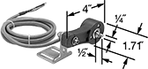
Rotary Encoders
Aluminum Body and Stainless Steel Shaft
 |  |
Shown with Wheel and Mounting Bracket (Both Sold Separately) |
Quadrature Output Channel—Transmitters with a quadrature output channel must be used with a controller that has quadrature detection to get a 4X resolution increase.
Shaft | Overall | Mounting Plate | Mounting Holes | |||||||||||||||
|---|---|---|---|---|---|---|---|---|---|---|---|---|---|---|---|---|---|---|
For Counter Function | Encoder Output Channel | Resolution Increase | For Max. Shaft Speed, rpm | Input Voltage, V DC | Coupling Req. | Dia. | Lg. | Lg. | Ht. | Lg. | Wd. | Ctr.-to-Ctr. | Thread Size | Choose a Resolution | Each | |||
Single Output Channel—250 mA Output Current | ||||||||||||||||||
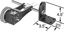
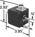
| Up | A | 2X | 6,000 | 5 to 28 | Yes | 3/8" | 3/4" | 3.95" | 2.93" | 2 1/4" | 2 1/4" | 1.41" | 6-32 | 10, 60, 100, 120, 500, 600, 1,200 | 16695T46 | 0000000 | ||
Quadrature Output Channel—250 mA Output Current | ||||||||||||||||||
| Up and Down | A, B | 2X, 4X | 6,000 | 5 to 28 | Yes | 3/8" | 3/4" | 3.95" | 2.93" | 2 1/4" | 2 1/4" | 1.41" | 6-32 | 10, 60, 100, 120, 500, 600, 1,200 | 16695T47 | 000000 | ||
Sanitary Rotary Encoders
 |
Also known as encoders, these sanitary transmitters convey motion to an electrical signal that conveys distance, direction, and speed. They’re often used in control systems to automate servomotors, robotics, and assembly machines in sanitary environments such as food and pharmaceutical plants. Made of corrosion-resistant stainless steel, they won’t rust from frequent washdowns with harsh cleaners. These transmitters are sealed and have a highly polished surface, leaving no room for bacteria to grow and making them easier to clean. They’re rated IP67 for protection from dust, high-pressure jets of water, and submersion in up to a meter of water for 30 minutes.
To achieve a 4X resolution increase, use these transmitters with a controller that has quadrature detection.
Use a flexible shaft coupling to connect the transmitter shaft to a drive shaft.
316 Stainless Steel Body and 303 Stainless Steel Shaft
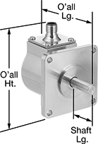
Shaft | Overall | Mounting Plate | Mounting Holes | |||||||||||||||||
|---|---|---|---|---|---|---|---|---|---|---|---|---|---|---|---|---|---|---|---|---|
For Counter Function | Encoder Output Channel | Resolution | Resolution Increase | For Max. Shaft Speed, rpm | Input Voltage, V DC | Coupling Req. | Dia. | Lg. | Lg. | Ht. | Lg. | Wd. | No. of | Ctr.-to-Ctr. | Dia. | Certification | Each | |||
Quadrature with Index Output Channel—20 mA Output Current | ||||||||||||||||||||
| Up and Down | A, B, Z | 600 | 2X, 4X | 8,000 | 4.75 to 28 | Yes | 3/8" | 1 1/16" | 3.175" | 3 1/4" | 2 1/2" | 2 1/2" | 4 | 2.06" | 7/32" | CE Marked | 4136N111 | 000000000 | ||
| Up and Down | A, B, Z | 3,600 | 2X, 4X | 8,000 | 4.75 to 28 | Yes | 3/8" | 1 1/16" | 3.175" | 3 1/4" | 2 1/2" | 2 1/2" | 4 | 2.06" | 7/32" | CE Marked | 4136N116 | 00000000 | ||
 |
Lg., ft. | Each | ||
|---|---|---|---|
| 32 | 4136N127 | 0000000 |
Compact Rotary Encoders
Incremental Optical Encoders with Shaft
 |  |
Wire Lead Connection—NPN Open Collector | 5-Pole Micro M12 Plug-In Connection—IO-Link |
Incremental transmitters track how much a rotating shaft has turned relative to a reference point. They need to be reset after a power loss.
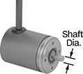
Transmitters with a shaft connect to a motor’s shaft with a flexible shaft coupling to fit different diameters.
NPN Open Collector—Transmitters with an NPN open collector pair with a resistor. Use these transmitters with a controller that has quadrature detection to get a 4X resolution increase.
IO-Link Communication Protocol—Transmitters with IO-Link let you set their resolution remotely when connected to a PLC, a human-machine interface (HMI), or a computer.
IP64 Enclosure Rating and IP65 Enclosure Rating—IP-rated transmitters are protected from dust and water.
Encoders | Connectors | ||||||||||||||||||
|---|---|---|---|---|---|---|---|---|---|---|---|---|---|---|---|---|---|---|---|
Mounting Holes | |||||||||||||||||||
Shaft Dia. | Rotary Encoder Type | Input Voltage, V DC | Max. Input Current, mA | Output Current, mA | Encoder Output Channel Type | For Max. Shaft Speed, rpm | Body Material | Housing Material | Enclosure Rating | No. of | Thread Size | Fasteners Included | Choose a Resolution | Each | Each | ||||
Wire Lead Connection—NPN Open Collector | |||||||||||||||||||
| 1/4" | Single Turn | 5 to 28 | 65 | 20 | Quadrature with Index | 8,000 | Aluminum | Plastic | IP64 | 3 | M3 × 0.5 mm | No | 500, 1,000, 2,000, 2,500 | 9749T3 | 0000000 | ——— | 0 | ||
5-Pole Micro M12 Plug-In Connection—IO-Link | |||||||||||||||||||
| 6 mm | Single Turn | 5 to 30 | 150 | 50 | — | 12,000 | Stainless Steel | Aluminum | IP65 | 3 | M4 × 0.7 mm | No | 1 to 10,000 | 9749T519 | 000000 | 4490N15 | 000000 | ||
| 10 mm | Single Turn | 5 to 30 | 150 | 50 | — | 12,000 | Stainless Steel | Aluminum | IP65 | 3 | M4 × 0.7 mm | No | 1 to 10,000 | 9749T521 | 000000 | 4490N15 | 00000 | ||
Incremental Optical Encoders with Shaft Opening
 |  |
Wire Lead Connection—NPN Open Collector | 5-Pole Micro M12 Plug-In Connection—IO-Link |
Incremental transmitters track how much a rotating shaft has turned relative to a reference point. They need to be reset after a power loss.
Transmitters with a shaft opening slide onto your motor's shaft. Their mounting plate flexes to compensate for your motor's vibration.
NPN Open Collector—Transmitters with an NPN open collector pair with a resistor. Use these transmitters with a controller that has quadrature detection to get a 4X resolution increase.
IO-Link Communication Protocol—Transmitters with IO-Link let you set their resolution remotely when connected to a PLC, a human-machine interface (HMI), or a computer.
IP64 Enclosure Rating and IP65 Enclosure Rating—IP-rated transmitters are protected from dust and water.
Encoders | Connectors | ||||||||||||||||||||||
|---|---|---|---|---|---|---|---|---|---|---|---|---|---|---|---|---|---|---|---|---|---|---|---|
Mounting Holes | |||||||||||||||||||||||
For Shaft Dia. | Rotary Encoder Type | Input Voltage, V DC | Max. Input Current, mA | Output Current, mA | Encoder Output Channel Type | For Max. Shaft Speed, rpm | Body Material | Housing Material | Enclosure Rating | Mounting Plate Dia. | Mounting Plate Wd. | For Screw Size | No. of | Ctr.-to-Ctr. | Thread Size | Fasteners Included | Choose a Resolution | Each | Each | ||||
Wire Lead Connection—NPN Open Collector | |||||||||||||||||||||||
| 1/4" | Single Turn | 5 to 28 | 65 | 20 | Quadrature with Index | 8,000 | Aluminum | Plastic | IP64 | — | 2.16" | No. 6 | 2 | 1.81" | — | No | 500, 1,000, 2,000, 2,500 | 9749T1 | 0000000 | ——— | 0 | ||
| 3/8" | Single Turn | 5 to 28 | 65 | 20 | Quadrature with Index | 8,000 | Aluminum | Plastic | IP64 | — | 2.16" | No. 6 | 2 | 1.81" | — | No | 500, 1,000, 2,000, 2,500 | 9749T2 | 000000 | ——— | 0 | ||
5-Pole Micro M12 Plug-In Connection—IO-Link | |||||||||||||||||||||||
| 6 mm | Single Turn | 5 to 30 | 150 | 50 | — | 12,000 | Stainless Steel | Aluminum | IP65 | 1.43" | — | — | 4 | — | M2.5 × 0.5 mm | No | 1 to 10,000 | 9749T522 | 000000 | 4490N15 | 000000 | ||
| 10 mm | Single Turn | 5 to 30 | 150 | 50 | — | 12,000 | Stainless Steel | Aluminum | IP65 | 1.43" | — | — | 4 | — | M2.5 × 0.5 mm | No | 1 to 10,000 | 9749T523 | 000000 | 4490N15 | 00000 | ||
Absolute Optical Encoders with Shaft
| |
Wire Lead Connection—SSI | 5-Pole Micro M12 Plug-In Connection—IO-Link |
Absolute transmitters give you the exact position of the shaft, even after a power loss.
Transmitters with a shaft connect to a motor’s shaft with a flexible shaft coupling to fit different diameters.
IO-Link Communication Protocol—Transmitters with IO-Link let you set their resolution remotely when connected to a PLC, a human-machine interface (HMI), or a computer.
Multi-Turn Rotary Encoder—Multi-turn absolute transmitters count how many full turns a shaft makes. They’re often used to keep print rollers aligned over multiple rotations.
IP65 Enclosure Rating—IP-rated transmitters are protected from dust and water.
Encoders | Connectors | |||||||||||||||||
|---|---|---|---|---|---|---|---|---|---|---|---|---|---|---|---|---|---|---|
Mounting Holes | ||||||||||||||||||
Shaft Dia. | Rotary Encoder Type | Input Voltage, V DC | Max. Input Current, mA | Output Current, mA | For Max. Shaft Speed, rpm | Body Material | Housing Material | Enclosure Rating | No. of | Thread Size | Fasteners Included | Bit Resolution, bit | Each | Each | ||||
Wire Lead Connection—SSI | ||||||||||||||||||
| 1/4" | Single Turn | 5 to 32 | 50 | 100 | 12,000 | Aluminum | Stainless Steel | IP65 | 4 | M3 × 0.5 mm | No | 12 | 9749T515 | 0000000 | ——— | 0 | ||
| 1/4" | Multi-Turn | 5 to 32 | 50 | 100 | 12,000 | Aluminum | Stainless Steel | IP65 | 4 | M3 × 0.5 mm | No | 24 | 9749T516 | 000000 | ——— | 0 | ||
| 6 mm | Single Turn | 5 to 32 | 50 | 100 | 12,000 | Aluminum | Stainless Steel | IP65 | 4 | M3 × 0.5 mm | No | 12 | 9749T517 | 000000 | ——— | 0 | ||
| 6 mm | Multi-Turn | 5 to 32 | 50 | 100 | 12,000 | Aluminum | Stainless Steel | IP65 | 4 | M3 × 0.5 mm | No | 24 | 9749T518 | 000000 | ——— | 0 | ||
5-Pole Micro M12 Plug-In Connection—IO-Link | ||||||||||||||||||
| 6 mm | Multi-Turn | 18 to 30 | 75 | 50 | 12,000 | Stainless Steel | Aluminum | IP65 | 3 | M4 × 0.7 mm | No | 1 to 31 | 9749T525 | 000000 | 4490N15 | 000000 | ||
| 10 mm | Multi-Turn | 18 to 30 | 75 | 50 | 12,000 | Stainless Steel | Aluminum | IP65 | 3 | M4 × 0.7 mm | No | 1 to 31 | 9749T524 | 000000 | 4490N15 | 00000 | ||
Absolute Optical Encoders with Shaft Opening
|
Wire Lead Connection—SSI |
Absolute transmitters give you the exact position of the shaft, even after a power loss.
Transmitters with a shaft opening slide onto your motor's shaft. Their mounting plate flexes to compensate for your motor's vibration.
Multi-Turn Rotary Encoder—Multi-turn absolute transmitters count how many full turns a shaft makes. They’re often used to keep print rollers aligned over multiple rotations.
Mounting Holes | |||||||||||||||||
|---|---|---|---|---|---|---|---|---|---|---|---|---|---|---|---|---|---|
For Shaft Dia. | Rotary Encoder Type | Input Voltage, V DC | Max. Input Current, mA | Output Current, mA | For Max. Shaft Speed, rpm | Body Material | Housing Material | Mounting Plate Wd. | For Screw Size | No. of | Ctr.-to-Ctr. | Fasteners Included | Bit Resolution, bit | Each | |||
Wire Lead Connection—SSI | |||||||||||||||||
| 1/4" | Single Turn | 5 to 24 | 100 | 420 | 8,000 | Aluminum | Plastic | 2.16" | No. 6 | 2 | 1.81" | No | 12 | 9749T511 | 0000000 | ||
| 1/4" | Multi-Turn | 5 to 24 | 100 | 420 | 8,000 | Aluminum | Plastic | 2.16" | No. 6 | 2 | 1.81" | No | 24 | 9749T512 | 000000 | ||
| 3/8" | Single Turn | 5 to 24 | 100 | 420 | 8,000 | Aluminum | Plastic | 2.16" | No. 6 | 2 | 1.81" | No | 12 | 9749T513 | 000000 | ||
| 3/8" | Multi-Turn | 5 to 24 | 100 | 420 | 8,000 | Aluminum | Plastic | 2.16" | No. 6 | 2 | 1.81" | No | 24 | 9749T514 | 000000 | ||
Programmable Rotary Encoders
Encoders with Shaft
 |
Transmitters with a shaft connect to motor shafts with a flexible shaft coupling, so they can be adapted to different diameters.
Shaft Dia. | Encoder Output Signal | Input Voltage, V DC | Max. Input Current, mA | Output Current, mA | For Max. Shaft Speed, rpm | Body Material | Housing Material | Enclosure Rating | Mounting Hole Thread Size | Fasteners Included | Resolution | Each | |||
|---|---|---|---|---|---|---|---|---|---|---|---|---|---|---|---|
Incremental Optical Encoder | |||||||||||||||
| 1/4" | Line Driver, NPN Open Collector, Push-Pull | 5 to 30 | 65 | 20 | 8,000 | Aluminum | Aluminum | IP67 | 10-32 | No | 1 to 65,536 | 9924N121 | 0000000 | ||
| 3/8" | Line Driver, NPN Open Collector, Push-Pull | 5 to 30 | 65 | 20 | 8,000 | Aluminum | Aluminum | IP67 | 10-32 | No | 1 to 65,536 | 9924N122 | 000000 | ||
 |
Data Connection | Each | ||
|---|---|---|---|
| USB-A | 9924N125 | 0000000 |
Encoders with Shaft Opening
 |
Transmitters with a shaft opening can be mounted anywhere along a motor shaft—just slide them on. They have a flexible mounting plate that compensates for shaft misalignment and vibration.
For Shaft Dia. | Encoder Output Signal | Input Voltage, V DC | Max. Input Current, mA | Output Current, mA | For Max. Shaft Speed, rpm | Body Material | Housing Material | Enclosure Rating | Mounting Plate Wd. | For Screw Size | Fasteners Included | Resolution | Each | |||
|---|---|---|---|---|---|---|---|---|---|---|---|---|---|---|---|---|
Incremental Optical Encoder | ||||||||||||||||
| 1/4" | Line Driver, NPN Open Collector, Push-Pull | 5 to 30 | 65 | 20 | 6,000 | Aluminum | Aluminum | IP67 | 2.83" | No. 6 | No | 1 to 65,536 | 9924N123 | 0000000 | ||
| 3/8" | Line Driver, NPN Open Collector, Push-Pull | 5 to 30 | 65 | 20 | 6,000 | Aluminum | Aluminum | IP67 | 2.83" | No. 6 | No | 1 to 65,536 | 9924N124 | 000000 | ||
|
Data Connection | Each | ||
|---|---|---|---|
| USB-A | 9924N125 | 0000000 |
